
Subscribe to Our Youtube Channel
Related Manuals for Sunny Health & Fitness SF-BH6422


Summary of Contents for Sunny Health & Fitness SF-BH6422
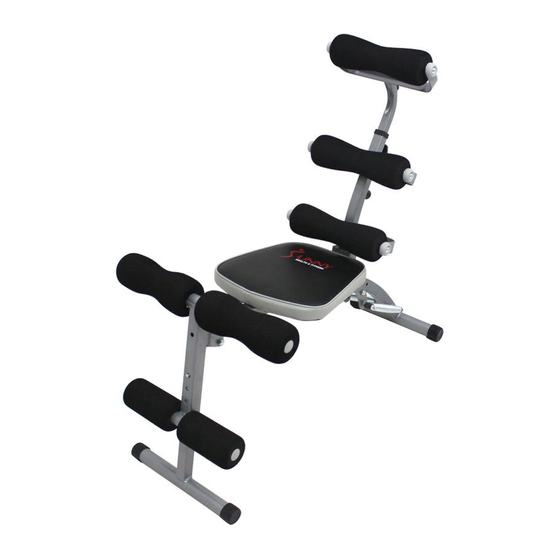
- Page 1 POWER AB BENCH SF-BH6422 USER MANUAL IMPORTANT: Read all instructions carefully before using this product. Retain owner’s manual for future reference. For customer service, please contact: support@sunnyhealthfitness.com...
-
Page 2: Important Safety Information
IMPORTANT SAFETY INFORMATION We thank you for choosing our product. To ensure your safety and health, please use this equipment correctly. It is important to read this entire manual before assembling and using the equipment. Safe and effective use can only be achieved if the equipment is assembled, maintained and used properly. -
Page 3: Exploded Drawing
EXPLODED DRAWING... -
Page 4: Parts List
PARTS LIST Part Description Qty. Foam Roller Main Frame Upper Leg Cross Bar Screw Foam Roller Locking Pin Adjustment Pin Spring Adjustment Knob Headrest Tube Allen Wrench... - Page 5 ASSEMBLY INSTRUCTIONS LOCKING PIN STEP: 1 Open the box and remove the Main Frame (No. 2). Unfold the main frame so that it matches the position of the drawing shown above. Next, align the holes on the securing points of the main frame (as shown above) and fix by inserting the Locking Pins (No. STEP: 2 Raise the back support upward.
- Page 6 STEP: 3 Connect the Springs (No. 8) to the two pegs located at the bottom end of the Main Frame (No. 2) just above the rear stabilizer. NOTE: In order to use the spring feature of this bench you must insure that the Adjustment Pin (No.
- Page 7 STEP: 5 Attach two sets of Foam Rollers (No. 1 and No. 5) onto the Upper Leg Cross Bar (No. 3) and lower leg cross bar located above the front stabilizer. STEP: 6 Insert the Headrest Tube (No. 10) into the top end of the back support on the Main Frame (No.
- Page 8 STEP: 7 The assembly is complete!
-
Page 9: Operation And Maintenance
OPERATION & MAINTENANCE OPERATING INSTRUCTIONS: 1. Please read all instructions before attempting to assemble the equipment. While assembling and during the use of the equipment, please make sure to follow all instructions carefully, any improper techniques of use and/or assembly may result in injury and/or damage to the equipment. - Page 10 THREE PART ANGLE ADJUSTMENT 1. Front Support Tube Adjustment INCLINE LEVEL 1 INCLINE LEVEL 2 INCLINE LEVEL 3...
- Page 11 2. Backrest Adjustment NOTE: When adjusting the backrest to any of the positions shown below, the Adjustment Pin (No. 7) must be inserted into the desired holes. 45 DEGREE ANGLE 85 DEGREE ANGLE FLAT 3. Headrest Tube Adjustment LEVEL 1 LEVEL 2 LEVEL 3...
Need help?
Do you have a question about the SF-BH6422 and is the answer not in the manual?
Questions and answers