
Related Manuals for MR OILTAP R


Summary of Contents for MR OILTAP R
- Page 1 On-Load Tap-Changer OILTAP® R Installation and Commissioning Instructions 4427410/00 EN...
- Page 2 © All rights reserved by Maschinenfabrik Reinhausen Dissemination and reproduction of this document and use and disclosure of its content are strictly prohibited unless expressly permitted. Infringements will result in liability for compensation. All rights reserved in the event of the granting of patents, utility models or designs.
-
Page 3: Table Of Contents
Table of contents Table of contents Introduction......................... 7 Validity..............................7 Manufacturer............................7 Subject to change without notice......................7 Completeness............................7 Safekeeping............................8 Notation conventions........................... 8 1.6.1 Symbols................................. 8 1.6.2 Hazard communication system..........................9 1.6.3 Information system.............................. 11 Safety..........................12 General safety information........................ 12 Appropriate use.......................... - Page 4 Table of contents RS protective relay..........................24 3.4.1 Function description............................24 3.4.2 Setup/models of protective relay......................... 24 Pressure monitoring device DW......................26 3.5.1 Function description............................26 3.5.2 Structure/versions of the pressure-operated relay....................27 OF 100 Oil Filter Unit......................... 29 Packaging, transport and storage................... 30 Packaging............................
- Page 5 Table of contents Fitting protective devices and drive components................116 5.5.1 Connecting the tap-change supervisory control (if installed)................116 5.5.2 Installing protective relay in piping and connecting................... 117 5.5.3 Installing and connecting the pressure-operated relay..................128 5.5.4 Fitting motor-drive unit............................131 5.5.5 Fitting bevel gear...............................
- Page 6 Table of contents Fault elimination......................180 Tripping of the protective relay and re-commissioning the transformer........... 182 9.1.1 Flap valve in IN SERVICE position........................183 9.1.2 Flap valve in OFF position..........................183 9.1.3 Re-commissioning the transformer........................183 Tripping the pressure-operated relay and putting the transformer back into operation....184 9.2.1 Sensor in the OPERATION position........................
-
Page 7: Introduction
1 Introduction Introduction This technical file contains detailed descriptions of the safe and proper in- stallation, connection, and commissioning of the product. It also includes safety instructions and general information about the prod- uct. Information about operation can be found in the operating instructions. This technical file is intended solely for specially trained and authorized per- sonnel. -
Page 8: Safekeeping
1 Introduction The following documents apply: ▪ Unpacking instructions (included in the scope of delivery) ▪ Supplement (included in the scope of delivery) ▪ Routine test report (included in the scope of delivery) ▪ Connection diagrams (included in the scope of delivery) ▪... -
Page 9: Hazard Communication System
1 Introduction Symbol Meaning Use your hand Adapter ring Apply a coat of paint Use a file Grease Coupling bolt Use a ruler Use a saw Hose clip Wire eyelet, safety wire Use a screwdriver Table 1: Symbols 1.6.2 Hazard communication system Warnings in this technical file are displayed as follows. - Page 10 1 Introduction Type and source of danger WARNING Consequences ► Action ► Action 1.6.2.2 Embedded warning information Embedded warnings refer to a particular part within a section. These warn- ings apply to smaller units of information than the warnings relating to sec- tions.
-
Page 11: Information System
1 Introduction Pictogram Meaning Warning of danger of tipping Table 3: Pictograms used in warning notices 1.6.3 Information system Information is designed to simplify and improve understanding of particular procedures. In this technical file it is laid out as follows: Important information. -
Page 12: Safety
2 Safety Safety General safety information This technical file contains detailed descriptions of the safe and proper in- stallation, connection, and commissioning of the product. ▪ Read this technical file through carefully to familiarize yourself with the product. ▪ Particular attention should be paid to the information given in this chap- ter. -
Page 13: Inappropriate Use
2 Safety On-load tap-change operations are not to be performed during operating conditions with higher currents. Examples of such operating conditions are: ▪ Inrush current impulses when transformers are switched on ▪ Short circuit The rated step voltage may be briefly exceeded by up to 10 % as long as the rated through current is not exceeded. -
Page 14: Personal Protective Equipment
2 Safety ▪ The product is only used when in a sound operational condition and safety equipment in particular is checked regularly for operational relia- bility. ▪ Only replacement parts, lubricants and auxiliary materials which are au- thorized by the manufacturer are used. ▪... -
Page 15: Protective Devices
2 Safety Wear the following in spe- Special personal protective equipment cial environments is needed in special environments. The choice of equipment depends on the circumstances. Safety glasses To protect the eyes from flying parts and splashing liquids. Hard hat To protect from falling and flying parts and materials. -
Page 16: Rupture Disk
2.7.4 Pressure relief device MPreC® On request, in place of the rupture disk MR will supply a pre-fitted pressure relief device MPreC® that responds to a defined overpressure in the oil com- partment of the on-load tap-changer. -
Page 17: Product Description
3 Product description Product description This chapter contains an overview of the design and function of the product. Scope of delivery The product is packaged with protection against moisture and is usually de- livered as follows: ▪ Oil compartment with on-load tap-changer head and built-in diverter switch insert ▪... -
Page 18: Setup/Versions
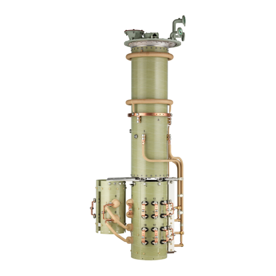
3 Product description Figure 1: System overview of on-load tap-changer transformer Transformer tank Gear unit Motor-drive unit On-load tap-changer Vertical drive shaft Protective relay Bevel gear Oil conservator Horizontal drive shaft Active part 3.2.2 Setup/versions The on-load tap-changer consists of the on-load tap-changer head, oil com- partment with built-in diverter switch insert, and the tap selector mounted be- low (also available with change-over selector on request). - Page 19 3 Product description Figure 2: OILTAP® R on-load tap-changer On-load tap-changer head Tap selector Oil compartment Change-over selector 3.2.2.1 Pipe connections The on-load tap-changer head features 4 pipe connections for different pur- poses. Depending on the order, some or all of these pipe connections are fitted with pipe bends ex factory.
-
Page 20: Name Plate
3 Product description Figure 3: Pipe connections with pipe bends Pipe connection Q Pipe connection Q is closed with a blank cover and, depending on the on- load tap-changer type, is intended for the bushing of the tap-change supervi- sory control supplied as an option or for connecting the oil filter unit. The functions of the R and Q pipe connections can be interchanged. -
Page 21: Drive Shaft
3 Product description Figure 4: Position of name plate Drive shaft 3.3.1 Function description The drive shaft is the mechanical connection between motor-drive and on- load tap-changer head / off-circuit tap-changer head. The bevel gear changes the direction from vertical to horizontal (see drawing 892916). - Page 22 3 Product description 3.3.2.1 Drive shaft without cardan shaft, without insulator (= normal model) Figure 5: Drive shaft without cardan shaft, without insulator (= normal model) Configuration V 1 min Intermediate bearing [mm] for [mm] Middle of hand crank – middle V 1 >...
- Page 23 3 Product description 3.3.2.3 Drive shaft with cardan shaft, without insulator (= special model) Figure 7: Drive shaft with cardan shaft, without insulator (= special model) Configuration V 1 min Intermediate bearing [mm] for [mm] Middle of hand crank – middle V 1 >...
-
Page 24: Rs Protective Relay
3 Product description RS protective relay 3.4.1 Function description The protective relay is used to protect the on-load tap-changer and the transformer when a malfunction occurs in the diverter switch oil compartment or selector switch oil compartment. It is tripped when the specified speed of oil flow from the on-load tap-changer head to the oil conservator is exceeded due to a fault. - Page 25 3 Product description Rear view Figure 10: RS 2001 Dummy plug Ventilation for terminal box Identification plate The protective relay RS 2001/R has an extra inspection window on the rear. Maschinenfabrik Reinhausen GmbH 2015 4427410/00 EN OILTAP® R...
-
Page 26: Pressure Monitoring Device Dw
3 Product description View from above Figure 11: RS 2001 Gasket Cable connection Grounding cable Protective cover Terminal box cover Dummy plug OPERATION (reset) test but- Connection terminals Slotted head screw Cylinder head screw for pro- tective conductor connection OFF (test tripping) test button The protective relay RS 2003 and RS 2004 has a 1/2"-14NPT adapter in place of the cable connection (position 7). -
Page 27: Structure/Versions Of The Pressure-Operated Relay
The pressure-operated relay responds faster than the RS 2001 protective re- lay in relation to large pressure increases. The RS 2001 protective relay is part of the default MR protection system that comes standard. Additional use of a pressure-operated relay also requires installation of the provided RS 2001 protective relay. - Page 28 3 Product description Figure 12: Snap-action switch and pressure measuring element Snap-action switch Pressure measuring element The snap-action switch has a normally open switch and normally closed switch with snap action. During operation, the snap-action switch and pressure measuring element are protected by a cover cap.
-
Page 29: Of 100 Oil Filter Unit
OF 100 oil filter unit with paper filter insert. The main- tenance intervals can therefore be extended. For more information, consult the MR operating instructions "OF 100 oil filter unit". You must use the OF 100 oil filter unit with combined filter insert for OILTAP®... -
Page 30: Packaging, Transport And Storage
4 Packaging, transport and storage Packaging, transport and storage Packaging The products are sometimes supplied with a sealed packaging and some- times also dried depending on what is required. A sealed packaging surrounds the packaged goods on all sides with plastic foil. -
Page 31: Transportation, Receipt And Handling Of Shipments
4 Packaging, transport and storage Transportation, receipt and handling of shipments Danger of death and damage to property! WARNING Danger of death and damage to property due to tipping or falling load! ► Transport crate only when closed. ► Do not remove the mounting material used in the crate during transport. ►... -
Page 32: Storage Of Shipments
4 Packaging, transport and storage changer/off-circuit tap-changer or contact Maschinenfabrik Reinhausen GmbH to agree on how to proceed with drying. If this is not done, the packaged goods may be damaged. ▪ Name the damaged parts. Hidden damage When damages are not determined until unpacking after receipt of the ship- ment (hidden damage), proceed as follows: ▪... -
Page 33: Unpacking Shipments And Checking For Transportation Damages
4 Packaging, transport and storage ▪ Unpack the packed goods and store in suitable storage space (well ven- tilated, as dust-free as possible, humidity < 50 % where possible). Unpacking shipments and checking for transportation damages NOTICE! ▪ Transport the packaged crate to the place where installation will take place. -
Page 34: Mounting
5 Mounting Mounting Risk of crushing from moving parts! WARNING When the on-load tap-changer undertakes a tap-change operation, compo- nents move on the selector and change-over selector, some of which are freely accessible. Reaching into the selector or change-over selector during a tap-change operation may result in serious injuries. -
Page 35: Fitting Mounting Flange On Transformer Cover
5 Mounting 5.1.1 Fitting mounting flange on transformer cover A mounting flange is required for fitting the on-load tap-changer head on the transformer cover. This can be supplied as an option or can be produced by the customer. Mounting flanges made by the customer must comply with the installation drawings in the appendix. -
Page 36: Installing The Standard Version On-Load Tap-Changer In The Transformer
5 Mounting Fit stud bolts on mounting flange. Figure 15: Tracing template, stud bolts Installing the standard version on-load tap-changer in the transformer Perform the work stated below in order to install the on-load tap-changer in the transformer (standard version). 5.2.1 Fastening on-load tap-changer to transformer cover This chapter describes how to fasten the on-load tap-changer to the trans-... - Page 37 5 Mounting Remove red-colored packaging material and transport material from oil compartment. Clean sealing surfaces on mounting flange and on-load tap-changer head, place oil-resistant gasket on mounting flange. Figure 16: Sealing surfaces, seal Maschinenfabrik Reinhausen GmbH 2015 4427410/00 EN OILTAP® R...
- Page 38 5 Mounting NOTICE! Lift the oil compartment by hooking up the on-load tap-chang- er head and carefully lower the oil compartment into the cover opening of the transformer. When lowering, take care not to damage the screen- ing rings (only present if Um ≥ 170 kV). Figure 17: Oil compartment Check that the on-load tap-changer head is mounted in the position specified by the design.
- Page 39 5 Mounting Screw on-load tap-changer head to mounting flange. Figure 18: On-load tap-changer head with mounting flange Remove the blocking device from the coupling of the oil compartment base. Figure 19: Blocking plate and shackle 5.2.1.2 Securing selector on oil compartment (selector size C/D) CAUTION! Place the selector on a level surface and secure it against tipping.
- Page 40 5 Mounting Remove red-colored packaging material and transport material from se- lector. Remove plastic bag with fastening materials from the selector and keep them ready. Figure 20: Plastic bag with fastening materials Remove the blocking strip from the selector coupling. Once the blocking strip is removed, the selector coupling must no longer be turned.
- Page 41 5 Mounting Remove the ring nuts from the selector. Figure 22: Ring nut NOTICE! Carefully lift selector below the oil compartment, ensuring that the selector take-off leads are free when lifting the selector on the oil compartment and do not touch the compartment. If this is not done, the selector take-off leads may be damaged.
- Page 42 5 Mounting 5.2.1.3 Securing selector on oil compartment (selector size E) CAUTION! Place the selector on a level surface and secure it against tipping. An unstably positioned selector may tip, resulting in seri- ous injuries and damage. Remove red-colored packaging material and transport material from se- lector.
- Page 43 5 Mounting Remove the ring nuts from the selector. Figure 26: Ring nut NOTICE! Carefully lift selector below the oil compartment, ensuring that the selector take-off leads are free when lifting the selector on the oil compartment and do not touch the compartment. If this is not done, the selector take-off leads may be damaged.
-
Page 44: Connecting Tap Winding And On-Load Tap-Changer Take-Off Lead
5 Mounting 5.2.1.4 Connecting tap selector take-off leads Proceed as follows to connect the tap selector take-off leads: NOTICE! Screw tap selector take-off lead to connecting piece with care. Comply with specified tightening torque and secure screw connection. Failure to do so may result in damage to the on-load tap-changer and transformer. - Page 45 5 Mounting Figure 29: Tap selector connection contacts 5.2.2.2 Change-over selector connection contacts for reversing change-over selector connection for selector size C/D The (+) and (-) change-over selector connection contacts are designed like tap selector connection contacts for reversing change-over selector connec- tions.
- Page 46 5 Mounting 5.2.2.3 Change-over selector connection contacts for coarse change-over selector connection for selector size C/D For coarse change-over selector connection, the (0) and (–) change-over se- lector connection contacts are designed like the tap selector connection con- tacts. The change-over selector connection contacts (+) are produced as ter- minal lugs of the crimped connecting lead (+/K) with a through-hole for M12 screws.
- Page 47 5 Mounting Figure 32: Tap selector connection contacts and change-over selector connection contacts Each screening cap is attached with a steel angle piece and 2 screws. The connection is secured by centre-punching at the perimeter of the screw head. The distance between the screening caps and adjacent selector take- off leads must be at least 25 mm! Figure 33: Screening caps 5.2.2.5...
-
Page 48: Carrying Out The Transformer Ratio Test
5 Mounting 5.2.2.6 Connecting on-load tap-changer take-off lead There are through-holes 13 mm in diameter at several points in the take-off ring of the oil compartment for connecting the on-load tap-changer take-off lead. Proceed as follows to connect the on-load tap-changer take-off lead: Connect the on-load tap-changer take-off lead to any through-hole on the take-off ring of the oil compartment. - Page 49 5 Mounting 5.2.3.1 Carrying out transformer ratio test with TAPMOTION® TD test drive Damage to the on-load tap-changer! NOTICE Performing too many operations without complete oil filling will damage the on-load tap-changer! ► Do not perform more than 250 tap-change operations on the on-load tap-changer without oil before drying.
- Page 50 5 Mounting Figure 35: Upper gear unit with hand crank If using more than one on-load tap-changer column with a shared drive, you have to link all on-load tap-changer heads to one another by the horizontal drive shaft part. NOTICE! Only move on-load tap-changer into the desired operating po- sition via drive shaft of the upper gear unit.
-
Page 51: Measuring Dc Resistance On Transformer
Drying on-load tap-changer in autoclave Dry on-load tap-changer using the following instructions to ensure the dielec- tric values assured by MR on the on-load tap-changer. If you want to dry the on-load tap-changer in an autoclave, first perform the drying process and then complete transformer assembly. - Page 52 5 Mounting 5.2.5.1 Vacuum-drying in the autoclave Before starting vacuum-drying in the autoclave, you must remove the on- load tap-changer head cover and on-load tap-changer accessories: NOTICE! Remove the on-load tap-changer head cover (24 screws M10/ wrench size 17 with safety elements) and store it outside the autoclave. If this is not done, the on-load tap-changer head cover may be dam- aged.
- Page 53 5 Mounting 5.2.5.2 Vapor-phase drying in the autoclave For vapor-phase drying in the autoclave, you must open the kerosene drain plug in the oil compartment base before drying so that the kerosene conden- sate can drain from the oil compartment. NOTICE! Unscrew kerosene drain plug between oil compartment base and selector gear clockwise until it starts to get hard to turn.
-
Page 54: Drying On-Load Tap-Changer In Transformer Tank
Drying on-load tap-changer in transformer tank Dry on-load tap-changer using the following instructions to ensure the dielec- tric values assured by MR on the on-load tap-changer. If you want to dry the on-load tap-changer in the transformer tank, first com- plete transformer assembly and then undertake drying. - Page 55 5 Mounting 5.2.6.2 Vapor-phase drying in the transformer tank For vapor-phase drying in the transformer tank, you have to open the kero- sene drain plug before drying so that the kerosene condensate can drain from the oil compartment. The kerosene drain plug is located in the oil compartment base and is not generally accessible from the outside.
- Page 56 5 Mounting 5.2.6.2.1.2 Removing on-load tap-changer head cover Danger of death or severe injury! WARNING Danger of death or severe injury from explosive gases under the on-load tap-changer head cover! ► Ensure that there are no naked flames, hot surfaces or sparks (for ex- ample caused by static charging) in the immediate surroundings and that none occur.
- Page 57 5 Mounting other work. Ensure that o-ring is in sound condition too. Damaged seal- ing surfaces lead to oil escaping and therefore to on-load tap-changer and transformer damage. Figure 41: On-load tap-changer head cover NOTICE! Do not expose the open oil compartment to ambient humidity for more than 10 hours.
- Page 58 5 Mounting 5.2.6.2.1.4 Disconnecting the plug connector of the tap-change supervisory control Danger of death or severe injury! WARNING Danger of death or severe injury from explosive gases under the on-load tap-changer head cover! ► Ensure that there is no supply voltage on the tap-change supervisory control.
- Page 59 5 Mounting Put part B of plug connector back in bracket. Figure 45: Placing part B of plug connector in bracket Swivel part A of plug connector out of on-load tap-changer head in di- rection indicated by arrow until it is between the pipe connections and the cable cannot be damaged when pulling out the diverter switch insert.
- Page 60 5 Mounting Insert the lifting gear in the brackets provided on the diverter switch in- sert carrier plate and position vertically above the diverter switch insert. Figure 48: Brackets on carrier plate Lift out the diverter switch insert slowly and vertically. Figure 49: Lifting out diverter switch insert CAUTION! Place the diverter switch insert on a level surface and se- cure it against tipping.
- Page 61 5 Mounting 5.2.6.2.2 Opening kerosene drain plug NOTICE! ► Unscrew kerosene drain plug with extended socket wrench counter-clockwise until it starts to get hard to turn.Never unscrew the kerosene drain plug all the way. Figure 50: Kerosene drain plug 5.2.6.2.3 Inserting diverter switch insert Proceed as follows to insert the diverter switch insert.
- Page 62 5 Mounting Insert the lifting gear in the brackets provided on the diverter switch in- sert carrier plate and position vertically above the diverter switch insert. Figure 52: Brackets on carrier plate Ensure that the red triangles on the coupling and carrier plate match up. Figure 53: Coupling OILTAP®...
- Page 63 5 Mounting Align diverter switch insert such that the red triangles at the top of the energy accumulator and on the on-load tap-changer head are opposite one another. Figure 54: Aligning diverter switch insert Slowly lower diverter switch insert. Secure carrier plate of diverter switch insert with bolts and safety ele- ments.
- Page 64 5 Mounting 5.2.6.2.3.2 Connecting tap-change supervisory control plug connector Lift part B of plug connector out of bracket. Figure 55: Part B of plug connector Connecting plug connector Figure 56: Connecting plug connector Place plug connector in bracket, secure leads on both sides of plug con- nector in retaining clamps.
- Page 65 5 Mounting ► Place tap position indicator disk on indicator drive shaft, slide spring clip on to shaft end. Figure 58: Tap position indicator disk 5.2.6.2.3.4 Securing on-load tap-changer head cover NOTICE! Place the on-load tap-changer head cover on the on-load tap- changer head and take care not to damage the o-ring inserted in the on- load tap-changer head cover.
- Page 66 5 Mounting Screw on-load tap-changer head cover using screws and safety ele- ments. Figure 60: On-load tap-changer head cover 5.2.6.2.4 Drying the on-load tap-changer Connect pipe connections R and Q of on-load tap-changer head to the kerosene vapor lead using one shared lead. Seal off unused pipe connections with a suitable blank cover.
-
Page 67: Installing The On-Load Tap-Changer In The Transformer (Bell-Type Tank Version)
5 Mounting Insert diverter switch insert. Installing the on-load tap-changer in the transformer (bell- type tank version) The following chapters explain how to install the on-load tap-changer in the transformer (bell-type tank version). 5.3.1 Inserting on-load tap-changer into supporting structure Proceed as follows to insert the on-load tap-changer in the supporting struc- ture: 5.3.1.1... - Page 68 5 Mounting Remove the ring nuts from the selector. Figure 63: Ring nut Remove the blocking strip from the selector coupling. Once the blocking strip is removed, the selector coupling must no longer be turned. Figure 64: Blocking strip CAUTION! Place the oil compartment on a level surface and secure it against tipping.
- Page 69 5 Mounting Lift the oil compartment by hooking up the on-load tap-changer head and remove the blocking device on the coupling of the oil compartment base. Figure 65: Blocking plate and shackle Carefully raise oil compartment above selector. Align the position of both coupling parts and attachment points on the oil compartment and the selector with one another.
- Page 70 5 Mounting 10. Screw selector onto oil compartment. Figure 66: Selector with oil compartment 5.3.1.2 Securing selector on oil compartment (selector size E) CAUTION! Place the selector on a level surface and secure it against tipping. An unstably positioned selector may tip, resulting in seri- ous injuries and damage.
- Page 71 5 Mounting Remove the ring nuts from the selector. Figure 68: Ring nut Remove the blocking strip from the selector coupling. Once the blocking strip is removed, the selector coupling must no longer be turned. Figure 69: Blocking strip NOTICE! Place the oil compartment on a level surface and secure it against tipping.
- Page 72 5 Mounting Lift the oil compartment by hooking up the on-load tap-changer head and remove the blocking device on the coupling of the oil compartment base. Figure 70: Blocking plate and shackle Carefully raise oil compartment above selector. Align the position of both coupling parts and attachment points on the oil compartment and the selector with one another.
- Page 73 5 Mounting 5.3.1.3 Connecting tap selector take-off leads Proceed as follows to connect the tap selector take-off leads: NOTICE! Screw tap selector take-off lead to connecting piece with care. Comply with specified tightening torque and secure screw connection. Failure to do so may result in damage to the on-load tap-changer and transformer.
- Page 74 5 Mounting are connected tension may occur which will damage the on-load tap- changer and transformer. There is also a risk of malfunctions from se- lector contacts closing incorrectly. Figure 73: On-load tap-changer with spacers on supporting structure Remove red supports on selector base (if present). Temporarily fasten on-load tap-changer to supporting structure.
-
Page 75: Connecting Tap Winding And On-Load Tap-Changer Take-Off Lead
5 Mounting 5.3.2 Connecting tap winding and on-load tap-changer take-off lead Damage to the on-load tap-changer! NOTICE Connecting leads which place mechanical strain on the on-load tap-changer will damage the on-load tap-changer! ► Produce connections with care. ► Do not twist connection contacts. ►... - Page 76 5 Mounting Figure 76: Change-over selector connection contacts for reversing change-over se- lector connection 5.3.2.3 Change-over selector connection contacts for coarse change-over selector connection for selector size C/D For coarse change-over selector connection, the (0) and (–) change-over se- lector connection contacts are designed like the tap selector connection con- tacts.
- Page 77 5 Mounting Figure 78: Tap selector connection contacts and change-over selector connection contacts Each screening cap is attached with a steel angle piece and 2 screws. The connection is secured by centre-punching at the perimeter of the screw head. The distance between the screening caps and adjacent selector take- off leads must be at least 25 mm! Figure 79: Screening caps 5.3.2.5...
-
Page 78: Carrying Out The Transformer Ratio Test
5 Mounting 5.3.2.6 Connecting on-load tap-changer take-off lead There are through-holes 13 mm in diameter at several points in the take-off ring of the oil compartment for connecting the on-load tap-changer take-off lead. Proceed as follows to connect the on-load tap-changer take-off lead: Connect the on-load tap-changer take-off lead to any through-hole on the take-off ring of the oil compartment. - Page 79 5 Mounting 5.3.3.1 Carrying out transformer ratio test with TAPMOTION® TD test drive Damage to the on-load tap-changer! NOTICE Performing too many operations without complete oil filling will damage the on-load tap-changer! ► Do not perform more than 250 tap-change operations on the on-load tap-changer without oil before drying.
- Page 80 5 Mounting Figure 81: Upper gear unit with hand crank If using more than one on-load tap-changer column with a shared drive, you have to link all on-load tap-changer heads to one another by the horizontal drive shaft part. NOTICE! Only move on-load tap-changer into the desired operating po- sition via drive shaft of the upper gear unit.
-
Page 81: Measuring Dc Resistance On Transformer
Drying on-load tap-changer in autoclave Dry on-load tap-changer using the following instructions to ensure the dielec- tric values assured by MR on the on-load tap-changer. If you want to dry the on-load tap-changer in an autoclave, first perform the drying process and then complete transformer assembly. - Page 82 5 Mounting 5.3.5.1 Vacuum-drying in the autoclave Before starting vacuum-drying in the autoclave, you must remove the on- load tap-changer head cover and on-load tap-changer accessories: NOTICE! Remove the on-load tap-changer head cover (24 screws M10/ wrench size 17 with safety elements) and store it outside the autoclave. If this is not done, the on-load tap-changer head cover may be dam- aged.
- Page 83 5 Mounting 5.3.5.2 Vapor-phase drying in the autoclave For vapor-phase drying in the autoclave, you must open the kerosene drain plug in the oil compartment base before drying so that the kerosene conden- sate can drain from the oil compartment. NOTICE! Unscrew kerosene drain plug between oil compartment base and selector gear clockwise until it starts to get hard to turn.
-
Page 84: Removing On-Load Tap-Changer Head
5 Mounting 5.3.6 Removing on-load tap-changer head 5.3.6.1 Removing on-load tap-changer head cover Danger of death or severe injury! WARNING Danger of death or severe injury from explosive gases under the on-load tap-changer head cover! ► Ensure that there are no naked flames, hot surfaces or sparks (for ex- ample caused by static charging) in the immediate surroundings and that none occur. - Page 85 5 Mounting Loosen screws with safety elements on the on-load tap-changer head cover. Figure 85: On-load tap-changer head cover NOTICE! Remove on-load tap-changer head cover. Check that the sealing surfaces on the on-load tap-changer head cover and on-load tap-changer head are in sound condition when removing and during all other work.
- Page 86 5 Mounting 5.3.6.2 Removing the tap position indicator ► Pull the spring clip off the shaft end and remove the tap position indica- tor disk. Figure 87: Tap position indicator disk 5.3.6.3 Disconnecting the plug connector of the tap-change supervisory control Danger of death or severe injury! WARNING...
- Page 87 5 Mounting Disconnect the plug connector. Figure 89: Disconnecting plug connector Put part B of plug connector back in bracket. Figure 90: Placing part B of plug connector in bracket Swivel part A of plug connector out of on-load tap-changer head in di- rection indicated by arrow until it is between the pipe connections and the cable cannot be damaged when pulling out the diverter switch insert.
- Page 88 5 Mounting Parts in the oil compartment may block the diverter switch insert, there- by damaging the on-load tap-changer and transformer. Check that you have the same number of parts when removing and installing. Figure 92: Carrier plate of diverter switch insert Insert the lifting gear in the brackets provided on the diverter switch in- sert carrier plate and position vertically above the diverter switch insert.
- Page 89 5 Mounting Lift out the diverter switch insert slowly and vertically. Figure 94: Lifting out diverter switch insert CAUTION! Place the diverter switch insert on a level surface and se- cure it against tipping. An unstably positioned diverter switch insert may tip, resulting in injuries and damage.
-
Page 90: Attaching Bell-Type Tank And Connecting On-Load Tap-Changer Head With On-Load Tap-Changer
5 Mounting 5.3.6.6 Lifting on-load tap-changer head off supporting flange Remove nuts and safety elements between on-load tap-changer head and supporting flange. Figure 96: On-load tap-changer head Lift on-load tap-changer head off supporting flange. Figure 97: On-load tap-changer head 5.3.7 Attaching bell-type tank and connecting on-load tap-changer head with on-load tap-changer The following chapters explain how to attach the bell-type tank and connect... - Page 91 5 Mounting 5.3.7.1 Mounting the bell-type tank Clean sealing surface of supporting flange, place o-ring on supporting flange. Figure 98: Supporting flange with o-ring Lift the bell-type tank over the active part of the transformer. Figure 99: Bell-type tank Maschinenfabrik Reinhausen GmbH 2015 4427410/00 EN OILTAP®...
- Page 92 5 Mounting 5.3.7.2 Mounting on-load tap-changer head on bell-type tank Clean sealing surfaces on mounting flange and on-load tap-changer head, place oil-resistant gasket on mounting flange. Figure 100: Mounting flange with gasket Gasket Mounting flange OILTAP® R 4427410/00 EN Maschinenfabrik Reinhausen GmbH 2015...
- Page 93 5 Mounting Position on-load tap-changer head on mounting flange such that the markings on the supporting flange and on-load tap-changer head match up. Note fitted bolt on supporting flange. Figure 101: Markings and fitted bolt Maschinenfabrik Reinhausen GmbH 2015 4427410/00 EN OILTAP®...
- Page 94 5 Mounting 5.3.7.3 Connecting on-load tap-changer head and on-load tap-changer NOTICE! Always lift the on-load tap-changer using the specified lifting traverse. If the connection screws from the supporting flange are used to lift the on-load tap-changer, the screws may be damaged, which makes it impossible to properly screw the on-load tap-changer and the on-load tap-changer head together! Figure 102: On-load tap-changer head...
- Page 95 5 Mounting Screw on-load tap-changer head to mounting flange. Figure 104: Screwing on-load tap-changer head to the mounting flange 5.3.7.4 Inserting oil suction pipe Lightly grease the O-rings of the oil suction pipe. Insert the oil suction pipe into the on-load tap-changer head. Make sure the O-rings are correctly fitted.
- Page 96 5 Mounting 5.3.7.5 Inserting diverter switch insert To fit the diverter switch insert, ensure that the selector coupling and in- dicator gear are in the adjustment position. Figure 106: Adjustment position Insert the lifting gear in the brackets provided on the diverter switch in- sert carrier plate and position vertically above the diverter switch insert.
- Page 97 5 Mounting Ensure that the red triangles on the coupling and carrier plate match up. Figure 108: Coupling Maschinenfabrik Reinhausen GmbH 2015 4427410/00 EN OILTAP® R...
- Page 98 5 Mounting Align diverter switch insert such that the red triangles at the top of the energy accumulator and on the on-load tap-changer head are opposite one another. Figure 109: Aligning diverter switch insert Slowly lower diverter switch insert. Ensure correct position of carrier plate in on-load tap-changer head. Area marked red must remain free.
- Page 99 5 Mounting 5.3.7.6 Connecting tap-change supervisory control plug connector Lift part B of plug connector out of bracket. Figure 111: Part B of plug connector Connecting plug connector Figure 112: Connecting plug connector Place plug connector in bracket, secure leads on both sides of plug con- nector in retaining clamps.
- Page 100 5 Mounting ► Place tap position indicator disk on indicator drive shaft, slide spring clip on to shaft end. Figure 114: Tap position indicator disk 5.3.7.8 Securing on-load tap-changer head cover NOTICE! Place the on-load tap-changer head cover on the on-load tap- changer head and take care not to damage the o-ring inserted in the on- load tap-changer head cover.
-
Page 101: Drying On-Load Tap-Changer In Transformer Tank
Drying on-load tap-changer in transformer tank Dry on-load tap-changer using the following instructions to ensure the dielec- tric values assured by MR on the on-load tap-changer. If you want to dry the on-load tap-changer in the transformer tank, first com- plete transformer assembly and then undertake drying. - Page 102 5 Mounting Seal off unused pipe connections with a suitable blank cover. Figure 117: Connecting lead Vacuum-drying in the transformer tank Heat up the on-load tap-changer in air at atmospheric pressure with a temperature increase of about 10 °C/h to a final temperature of maxi- mum 110 °C.
- Page 103 5 Mounting 5.3.8.2.1.1 Moving on-load tap-changer to adjustment position ► Move on-load tap-changer to adjustment position. Figure 118: Adjustment position 5.3.8.2.1.2 Removing on-load tap-changer head cover Danger of death or severe injury! WARNING Danger of death or severe injury from explosive gases under the on-load tap-changer head cover! ►...
- Page 104 5 Mounting Make sure that the inspection window is sealed with the cover. Loosen screws with safety elements on the on-load tap-changer head cover. Figure 119: On-load tap-changer head cover NOTICE! Remove on-load tap-changer head cover. Check that the sealing surfaces on the on-load tap-changer head cover and on-load tap-changer head are in sound condition when removing and during all other work.
- Page 105 5 Mounting 5.3.8.2.1.3 Removing the tap position indicator ► Pull the spring clip off the shaft end and remove the tap position indica- tor disk. Figure 121: Tap position indicator disk 5.3.8.2.1.4 Disconnecting the plug connector of the tap-change supervisory control Danger of death or severe injury! WARNING...
- Page 106 5 Mounting Disconnect the plug connector. Figure 123: Disconnecting plug connector Put part B of plug connector back in bracket. Figure 124: Placing part B of plug connector in bracket Swivel part A of plug connector out of on-load tap-changer head in di- rection indicated by arrow until it is between the pipe connections and the cable cannot be damaged when pulling out the diverter switch insert.
- Page 107 5 Mounting Parts in the oil compartment may block the diverter switch insert, there- by damaging the on-load tap-changer and transformer. Check that you have the same number of parts when removing and installing. Figure 126: Carrier plate of diverter switch insert Insert the lifting gear in the brackets provided on the diverter switch in- sert carrier plate and position vertically above the diverter switch insert.
- Page 108 5 Mounting Lift out the diverter switch insert slowly and vertically. Figure 128: Lifting out diverter switch insert CAUTION! Place the diverter switch insert on a level surface and se- cure it against tipping. An unstably positioned diverter switch insert may tip, resulting in injuries and damage.
- Page 109 5 Mounting 5.3.8.2.3.1 Inserting diverter switch insert To fit the diverter switch insert, ensure that the selector coupling and in- dicator gear are in the adjustment position. Figure 130: Adjustment position Insert the lifting gear in the brackets provided on the diverter switch in- sert carrier plate and position vertically above the diverter switch insert.
- Page 110 5 Mounting Ensure that the red triangles on the coupling and carrier plate match up. Figure 132: Coupling OILTAP® R 4427410/00 EN Maschinenfabrik Reinhausen GmbH 2015...
- Page 111 5 Mounting Align diverter switch insert such that the red triangles at the top of the energy accumulator and on the on-load tap-changer head are opposite one another. Figure 133: Aligning diverter switch insert Slowly lower diverter switch insert. Ensure correct position of carrier plate in on-load tap-changer head. Area marked red must remain free.
- Page 112 5 Mounting 5.3.8.2.3.2 Connecting tap-change supervisory control plug connector Lift part B of plug connector out of bracket. Figure 135: Part B of plug connector Connecting plug connector Figure 136: Connecting plug connector Place plug connector in bracket, secure leads on both sides of plug con- nector in retaining clamps.
- Page 113 5 Mounting ► Place tap position indicator disk on indicator drive shaft, slide spring clip on to shaft end. Figure 138: Tap position indicator disk 5.3.8.2.3.4 Securing on-load tap-changer head cover NOTICE! Place the on-load tap-changer head cover on the on-load tap- changer head and take care not to damage the o-ring inserted in the on- load tap-changer head cover.
- Page 114 5 Mounting Screw on-load tap-changer head cover using screws and safety ele- ments. Figure 140: On-load tap-changer head cover 5.3.8.2.4 Drying the on-load tap-changer Connect pipe connections R and Q of on-load tap-changer head to the kerosene vapor lead using one shared lead. Seal off unused pipe connections with a suitable blank cover.
-
Page 115: Filling The Oil Compartment Of The On-Load Tap-Changer With Oil
5 Mounting Insert diverter switch insert. Filling the oil compartment of the on-load tap-changer with After drying, completely fill the oil compartment (diverter switch insert fitted) with oil again as soon as possible so that an impermissible amount of humid- ity is not absorbed from the surroundings. -
Page 116: Fitting Protective Devices And Drive Components
5 Mounting Fill on-load tap-changer with oil using one of the remaining pipe connec- tions of the on-load tap-changer head. Figure 143: Pipe connection S and R Fitting protective devices and drive components 5.5.1 Connecting the tap-change supervisory control (if installed) Risk of fatal injury due to electrical voltage! DANGER Danger of death due to electrical voltage when assembling and connecting... -
Page 117: Installing Protective Relay In Piping And Connecting
5 Mounting 5.5.2 Installing protective relay in piping and connecting Always perform all transformer tests with the protective relay attached and connected. 5.5.2.1 Checking function of protective relay Check the function of the protective relay before installing in piping between on-load tap-changer head and oil conservator. - Page 118 5 Mounting Press OFF test button. ð Flap valve is inclined. Line marker appears in the middle of the in- spection window. Figure 145: OFF position Press IN SERVICE test button. ð Flap valve is vertical. Figure 146: In service position OILTAP®...
- Page 119 5 Mounting Close terminal box. Figure 147: Terminal box cover The associated contact positions for checking electrical continuity are evi- dent from the dimensional drawing provided. 5.5.2.2 Installing protective relay in piping The following requirements must be satisfied in order to install the protective relay in the piping: ▪...
- Page 120 5 Mounting ▪ Install protective relay such that it can be easily accessed for subse- quent maintenance work. Figure 148: Piping with inclination of at least 2 % Figure 149: Protective relay with test button at the top OILTAP® R 4427410/00 EN Maschinenfabrik Reinhausen GmbH 2015...
- Page 121 5 Mounting Figure 150: Reference arrow pointing towards the on-load tap-changer's oil conser- vator Install the protective relay horizontally in the pipe between on-load tap- changer head and oil conservator as near as possible to the on-load tap-changer head taking the above points into consideration. Provide a stop-cock (nominal width of at least 25 mm) between protec- tive relay and oil conservator.
- Page 122 2001/R) or adapter (RS 2003 und RS 2004) in the tapped hole which seems to be in the most favorable position. Figure 152: Cable bushing Seal open tapped hole with MR dummy plug. Figure 153: Dummy plug OILTAP® R 4427410/00 EN...
- Page 123 5 Mounting Open terminal box. Figure 154: Terminal box Maschinenfabrik Reinhausen GmbH 2015 4427410/00 EN OILTAP® R...
- Page 124 5 Mounting Loosen screw, remove terminal box cover and take off protective cover. Figure 155: Terminal box cover and protective cover OILTAP® R 4427410/00 EN Maschinenfabrik Reinhausen GmbH 2015...
- Page 125 5 Mounting Guide cable through cable bushing and into protective relay. Ensure that the cable connection is well secured and sealed. Figure 156: Cable bushing Risk of severe injury or death! WARNING Danger of death and severe injury due to unprofessional electrical connec- tion of protective relay.
- Page 126 5 Mounting Connect protective conductor to cylinder head screw. Figure 158: Protective conductor Insert protective cover. Figure 159: Protective cover OILTAP® R 4427410/00 EN Maschinenfabrik Reinhausen GmbH 2015...
- Page 127 5 Mounting Secure terminal box cover. Figure 160: Terminal box cover Maschinenfabrik Reinhausen GmbH 2015 4427410/00 EN OILTAP® R...
-
Page 128: Installing And Connecting The Pressure-Operated Relay
5 Mounting 10. Close terminal box. Figure 161: Terminal box cover 5.5.3 Installing and connecting the pressure-operated relay 5.5.3.1 Checking the function of the pressure-operated relay Check the function of the pressure-operated relay before you install it on a pipe bend or the on-load tap-changer head. Remove the cover cap. - Page 129 5 Mounting Figure 162: OFF position Snap-action switch Sensor in OFF position Activate the snap-action switch again. ð Sensor is in the OPERATION position below the snap-action switch. Maschinenfabrik Reinhausen GmbH 2015 4427410/00 EN OILTAP® R...
- Page 130 5 Mounting Figure 163: OPERATION position Snap-action switch Sensor in the OPERATION position Secure the cover cap. Always check the position of the sensor! 5.5.3.2 Installing the pressure-operated relay The pressure-operated relay can be installed in 2 variants. ▪ Fastening on the on-load tap-changer head (vertical installation) ▪...
-
Page 131: Fitting Motor-Drive Unit
Secure the cover cap. Ensure the fixing screw is positioned correctly, see Appendix. 5.5.4 Fitting motor-drive unit ► Fit motor-drive unit as described in relevant MR operating instructions "TAPMOTION® ED". 5.5.5 Fitting bevel gear The stamped serial number of the bevel gear must match the serial number of the on-load tap-changer. -
Page 132: Fitting Drive Shaft
5 Mounting The information provided above applies analogously to special design bevel gears and angle gears, as well as to intermediate bearings of the vertical or horizontal drive shaft. Refer to the information about the drive shaft in this technical file for more information. 5.5.6 Fitting drive shaft In accordance with IEC standard 60214, all drive shafts located on the out-... - Page 133 5 Mounting Standard lengths Motor-drive unit Manual drive 1700 • • 2000 • • 2500 Not permitted • Table 9: Graded standard lengths of square tubes The maximum total drive shaft length of the drive - last pole = 15 m. I>2000 only possible for vertical installation without shaft protection! Tele- scopic protective tubes for manual drives with vertical dimensions V1>...
- Page 134 5 Mounting NOTICE! Only align the gear unit by turning the drive shaft of the gear unit until the horizontal drive shaft is flush with the gear unit drive shaft. Never turn upper gear unit directly around its own axis to align it. Figure 165: Aligning gear unit Swivel pressure ring segments back towards gear unit and tighten screws.
- Page 135 5 Mounting Fitting horizontal drive shaft To fit the horizontal drive shaft, proceed as follows. Calculate dimension A between shaft end of upper gear unit and shaft end of bevel gear and shorten square tube to length A – 9 mm. Figure 167: Shortening square tube Calculate inside width B between housings of upper gear unit and bevel gear.
- Page 136 5 Mounting Slide loosely screwed together coupling part onto square tube until stop is reached. Figure 169: Sliding coupling part onto square tube Grease coupling bolt. Fit coupling bolt onto bevel gear and slide square tube with coupling part over it. Figure 170: Attaching coupling part to bevel gear OILTAP®...
- Page 137 5 Mounting Mount horizontal drive shaft on bevel gear. Figure 171: Mounting horizontal drive shaft on bevel gear Grease coupling bolts and coupling brackets for upper gear unit. Mount coupling brackets on upper gear unit. Figure 172: Mounting horizontal drive shaft on upper gear unit Maschinenfabrik Reinhausen GmbH 2015 4427410/00 EN OILTAP®...
- Page 138 5 Mounting Now attach shortened protective cover to housing lugs on the on-load tap-changer head and bevel gear. Secure each end of protective cover with a hose clip. Figure 173: Fitting protective cover If using a bearing block or angle gear, attach caps to the protective cov- Figure 174: Bearing block caps OILTAP®...
- Page 139 5 Mounting Figure 175: Angle gear caps 5.5.6.1.1 On-load tap-changer sets and combinations Due to the special arrangement of three and two-column designs, the on- load tap-changer heads must be coupled together above the transformer cover. Proceed as follows: Check that the operating positions of all on-load tap-changers are identi- cal (inspection window in the on-load tap-changer head).
- Page 140 5.5.6.2 Fitting vertical drive shaft Couple drive shaft with motor-drive unit and on-load tap-changer as descri- bed in MR operating instructions for TAPMOTION® ED. The motor-drive unit may be started by accident if the motor WARNING protective switch is not tripped! Risk of injury from starting the motor-drive unit by accident! ►...
- Page 141 5 Mounting To fit the vertical drive shaft to the drive, proceed as follows: Grease the coupling bolts, coupling brackets and ball heads, e.g. ISO- FLEX TOPAS L 32. Figure 176: Grease the coupling bolts, coupling brackets and ball heads. Maschinenfabrik Reinhausen GmbH 2015 4427410/00 EN OILTAP®...
- Page 142 5 Mounting Determine dimension A between the shaft end of the drive and the shaft end of the bevel gear. Shorten square tube to length of A–9 mm. Figure 177: Shortening square tube Deburr cut surface of square tube. Figure 178: Deburring cut surfaces OILTAP®...
- Page 143 5 Mounting Slide loosely screwed together coupling part onto square tube until stop is reached. Figure 179: Sliding coupling part onto square tube Insert coupling bolt into lower shaft end. Grease coupling parts and cou- pling bolts. Slide square tube with coupling part on to coupling bolt. Figure 180: Sliding square tube with coupling part on to coupling bolt Maschinenfabrik Reinhausen GmbH 2015 4427410/00 EN...
- Page 144 5 Mounting Secure vertical drive shaft to drive. Figure 181: Mounting vertical drive shaft on drive Pivot square tube with coupling part. Figure 182: Pivoting square tube When installing inner tube of telescopic protective tube, if necessary shorten on side without slits. The minimum dimension for overlapping the two protective tubes is 100 mm.
- Page 145 5 Mounting Figure 183: Deburring inner tube Dimension A (= distance be- Inner tube Outer tube tween the shaft end of the drive and the shaft end of the bevel gear) 170 mm...190 mm Shorten to 200 mm = 200 mm 191 mm...1130 mm Dimension = 200 mm...
- Page 146 5 Mounting Slide outer tube over inner tube (with slot at bottom). Slide telescopic protective tubes onto square tube. Then slide hose clips over telescopic protective tubes. Figure 184: Sliding on telescopic protective tube 10. Place adapter ring over bearing collar of bevel gear and slide upwards. Push in coupling bolt.
- Page 147 3 mm between the coupling bolt and upper coupling piece. To prepare for alignment, tighten screws to approx. 6 Nm. After aligning on- load tap-changer to drive (see MR operating instructions for TAPMOTION® ED), tighten screws to 9 Nm. Figure 186: Mounting coupling brackets...
- Page 148 5 Mounting 12. Attach protective tube (inner tube) with a hose clip to the bearing collar of the drive . Then slider upper protective tube (outer tube) over adapter on bevel gear . Secure upper protective tube with hose clip both at top end and at transition to bottom protective tube Figure 187: Mounting protective tube 5.5.6.3...
- Page 149 5 Mounting Figure 188: Drive shaft with cardan joint Maschinenfabrik Reinhausen GmbH 2015 4427410/00 EN OILTAP® R...
- Page 150 5 Mounting To fit the drive shaft with cardan joints, proceed as follows: Grease the coupling bolts, coupling brackets and ball heads, e.g. ISO- FLEX TOPAS L 32. Figure 189: Grease the coupling bolts, coupling brackets and ball heads. OILTAP® R 4427410/00 EN Maschinenfabrik Reinhausen GmbH 2015...
- Page 151 5 Mounting Insert adapter in neck of pivotable protective tubes . Place both parts of pivotable protective tube inside one another and turn towards one another to set the corresponding angle. Figure 190: Inserting adapter in pivotable protective tubes When supplied, the cardan joints are fitted with coupling bolts .
- Page 152 5 Mounting Connect shorter cardan joint supplied to ball-shaped head of motor- drive unit with cardan joint bolt. Figure 192: Fitting cardan joint to ball-shaped head of motor-drive unit Fit second, longer cardan joint to bevel gear. If a cardan joint is attached to the upper gear unit, then use a cardan joint with an inner hub diameter of 25 mm.
- Page 153 5 Mounting Provisionally connect loose shaft ends of the joints to an angle bar and align. Figure 195: Connecting shaft ends with angle bar Maschinenfabrik Reinhausen GmbH 2015 4427410/00 EN OILTAP® R...
- Page 154 5 Mounting Determine dimension A between the shaft ends. Cut square tube to LR = A + 106 mm (LR = length of square tube). Deburr cut surface of square tube. Figure 196: Shortening square tube OILTAP® R 4427410/00 EN Maschinenfabrik Reinhausen GmbH 2015...
- Page 155 5 Mounting Before mounting, shorten both telescopic tubes to dimension A/ 2 + 120 mm (A = dimension between both cardan joint ends) and de- burr. Figure 197: Shortening telescopic tubes 10. Fit one adapter to bearing collar of motor-drive unit and fit other adapter to bearing collar of bevel gear.
- Page 156 5 Mounting 11. Slide previously shortened and deburred square tube over upper cardan joint end until stop is reached. Figure 199: Sliding square tube over upper cardan joint end 12. Thread upper flexible protective tube with long outlet up onto square tube from below.
- Page 157 5 Mounting 13. Thread on outer and inner tubes such that the slotted sides of the outer and inner tube are both facing down. Figure 201: Sliding on telescopic tubes 14. Slide everything up and secure with a screw clamp. Figure 202: Securing everything with a screw clamp Maschinenfabrik Reinhausen GmbH 2015 4427410/00 EN...
- Page 158 5 Mounting 15. Slide bottom flexible protective tube (also with long outlet up) on to the square tube and secure with screw clamp. Figure 203: Sliding bottom flexible protective tube onto square tube OILTAP® R 4427410/00 EN Maschinenfabrik Reinhausen GmbH 2015...
- Page 159 To prepare for alignment, tighten screws to approx. 6 Nm. After aligning on- load tap-changer to drive (see MR operating instructions for TAPMOTION® ED), tighten screws to 9 Nm. Maschinenfabrik Reinhausen GmbH 2015 4427410/00 EN OILTAP®...
- Page 160 5 Mounting Figure 205: Tightening lower coupling brackets 18. Fit upper coupling brackets with 3 mm axial clearance. Figure 206: Fitting upper coupling brackets 19. Working from top to bottom, mount the individual parts of the shaft pro- tection. Set angle position between both parts of pivotable protective tube and fix with available hose clip.
- Page 161 5 Mounting The plastic adapters must be at the respective end of the pivotable protec- tive tube. Only slide telescopic pipe into upper and lower pivotable protec- tive tubes by the width of the adapter before tightening the hose clips. Figure 207: Securing telescopic pipes and flexible protective tubes with hose clips 5.5.6.4 Fitting drive shaft with insulator...
-
Page 162: Centering On-Load Tap-Changer And Motor-Drive Unit
Center on-load tap-changer and motor-drive unit as described in relevant MR operating instructions "TAPMOTION® ED". 5.5.8 Installing electrics for motor-drive unit Install electrics for motor-drive unit as described in relevant MR operating in- structions "TAPMOTION® ED". OILTAP® R 4427410/00 EN... -
Page 163: Commissioning The On-Load Tap-Changer At The Transformer Manufacturer's Site
6 Commissioning the on-load tap-changer at the transformer manufacturer's site Commissioning the on-load tap-changer at the transformer manufacturer's site Perform the following work and functional checks before commissioning the transformer. Bleeding on-load tap-changer head and suction pipe Before first commissioning, the on-load tap-changer head and the suction pipe on pipe connection S must be bled. -
Page 164: Bleeding Suction Pipe On Pipe Connection S
6 Commissioning the on-load tap-changer at the transformer manufacturer's site 6.1.2 Bleeding suction pipe on pipe connection S Remove screw cap from pipe connection S. Figure 212: Screw cap NOTICE! Open vent screw and bleed suction pipe. Make sure the suc- tion pipe is fully vented. -
Page 165: Performing Tests On Motor-Drive Unit
Performing tests on motor-drive unit Function tests ► Perform function checks as described in relevant MR operating instruc- tions "TAPMOTION® ED". Dielectric tests on transformer wiring ► Note information relating to dielectric tests on transformer wiring in the associated MR operating instructions "TAPMOTION®... -
Page 166: High-Voltage Tests On The Transformer
An incorrectly coupled motor-drive unit will damage the on-load tap-changer. Check, in both end positions, the function of the electrical and mechani- cal end stop (see MR operating instructions for the "TAPMOTION® ED"). High-voltage tests on the transformer... - Page 167 6 Commissioning the on-load tap-changer at the transformer manufacturer's site ▪ Guide all ground connecting leads to one central connection point (es- tablishment of suitable reference earth). ▪ Disconnect all electronic components before the high voltage test. Be- fore a wiring dielectric test, remove all devices with a withstand voltage of <...
-
Page 168: Transporting Transformer To The Operating Site
Do not actuate an on-load tap-changer which is not coupled and do not turn its drive shaft. Transport drive to installation site in the MR delivery packaging. Fit drive and drive shaft to transformer at the operating site (see page [►... -
Page 169: Transport Without Oil Fill
7 Transporting transformer to the operating site In case of a short-term immobilization time of maximum 4 weeks without an oil conservator, dropping the oil level in the on-load tap-changer head by about 5 liters is also sufficient. Transport without oil fill NOTICE! Completely empty the oil compartment of the on-load tap- changer if the transformer is completely emptied of oil.If this is not done,... - Page 170 7 Transporting transformer to the operating site Open air-vent valve again and drain off around 5–10 liters of oil via the pipe connection S until the area under the on-load tap-changer head cover is free of oil. Loosen 24 screws M10/wrench size 17 with safety elements on on-load tap-changer head cover.
-
Page 171: Commissioning The Transformer At The Operating Site
8 Commissioning the transformer at the operating site Commissioning the transformer at the operating site Before energizing the transformer, check that the motor-drive unit and pro- tective relay are functioning correctly and fill the on-load tap-changer oil compartment with new mineral insulating oil. Proceed as follows: Checking motor-drive unit Before commissioning the transformer, repeat the function tests on the mo- tor-drive unit as described in the operating instructions "TAPMOTION®... -
Page 172: Checking Protective Relay
8 Commissioning the transformer at the operating site Checking protective relay 8.2.1 Checking protective relay (RS 2001, 2001/V, 2001/H, 2001/E, 2001/5, 2001/R, 2003) Check that the protective relay is functioning correctly before commis- ü sioning the transformer: Ground the transformer on the high-voltage and low-voltage sides. En- sure that the working ground connection on the transformer is not re- moved during testing. -
Page 173: Filling The Oil Compartment Of The On-Load Tap-Changer With Oil
8 Commissioning the transformer at the operating site Ground the transformer on the high-voltage and low-voltage sides. En- sure that the working ground connection on the transformer is not re- moved during testing. Ensure that transformer remains de-energized during testing. Deactivate the automatic fire extinguishing device. - Page 174 8 Commissioning the transformer at the operating site NOTICE Damage to the on-load tap-changer! Damage to the on-load tap-changer by actuating the on-load tap-changer without oil! ► Before actuating the on-load tap-changer for the first time, the tap se- lector must be completely immersed in transformer oil and the oil com- partment completely filled with oil.
- Page 175 8 Commissioning the transformer at the operating site Establish a connecting lead between the pipe connection E2 and one of the pipe connections R, S or Q to ensure equal pressure during evacua- tion in the oil compartment and transformer. Figure 216: Connecting lead between E2 and Q.
-
Page 176: Bleeding On-Load Tap-Changer Head And Suction Pipe
8 Commissioning the transformer at the operating site Fill on-load tap-changer with new mineral insulating oil for transformers in accordance with IEC 60296 using one of the two free pipe connec- tions of the on-load tap-changer head. Figure 217: Pipe connection S and R Take oil sample from oil compartment. - Page 177 8 Commissioning the transformer at the operating site Remove screw cap on air-vent valve E1 on the on-load tap-changer head cover. Figure 218: Screw cap Use screwdriver to lift valve tappet on air-vent valve E1 and bleed on- load tap-changer head. Figure 219: Valve tappet Seal air-vent valve E1 with screw cap (tightening torque 10 Nm).
-
Page 178: Bleeding Suction Pipe On Pipe Connection S
8 Commissioning the transformer at the operating site 8.5.2 Bleeding suction pipe on pipe connection S Remove screw cap from pipe connection S. Figure 220: Screw cap NOTICE! Open vent screw and bleed suction pipe. Make sure the suc- tion pipe is fully vented. The insulation capability of the on-load tap- changer to ground will otherwise be significantly impaired. -
Page 179: Commissioning The Transformer
8 Commissioning the transformer at the operating site Check, in both end positions, the function of the electrical and mechani- cal end stop (see MR operating instructions for the "TAPMOTION® ED"). Commissioning the transformer Loop the signaling contact for falling below the minimum oil level in the on-load tap-changer's oil conservator into the tripping circuit of the cir- cuit breaker. -
Page 180: Fault Elimination
In the event of faults on the on-load tap-changer and motor-drive unit, which cannot be easily corrected on site, or if the RS protective relay or additional protective devices have been tripped, please inform your authorized MR rep- resentative, the transformer manufacturer or contact us directly at:... - Page 181 Ensure proper mounting of the drive shaft in ac- changing tap position cordance with its operating instructions. Check that hose clips and protective covers are seated cor- rectly. Contact MR in the event of noise from the motor-drive unit. Maschinenfabrik Reinhausen GmbH 2015 4427410/00 EN...
-
Page 182: Tripping Of The Protective Relay And Re-Commissioning The Transformer
9 Fault elimination Error pattern Action Red message on monitoring unit If possible read out database and send to MR along with error code. Warning or tripping of Buchholz relay on transform- Notify manufacturer of transformer. Deviation from desired value when measuring... -
Page 183: Flap Valve In In Service Position
9 Fault elimination 9.1.1 Flap valve in IN SERVICE position If the flap valve is in the IN SERVICE position, there may be a fault in the tripping circuit. Check the tripping circuit. If the reason for the protective relay tripping cannot be found, the diverter switch insert or selector switch insert must be removed in accordance with the on-load tap-changer's operating in- structions and checked... -
Page 184: Tripping The Pressure-Operated Relay And Putting The Transformer Back Into Operation
9 Fault elimination Tripping the pressure-operated relay and putting the transformer back into operation Risk of severe injury or death! WARNING Risk of severe injury or death if on-load tap-changer and transformer are in- sufficiently tested! ► Check the on-load tap-changer and transformer when a pressure-oper- ated relay has been tripped. -
Page 185: Re-Commissioning The Transformer
9 Fault elimination ▪ Were switching operations in the network being carried out at the instant of tripping? ▪ Were overvoltages registered at the instant of tripping? ▪ How high is the static pressure on the pressure relief device (height dif- ference between the oil level in the on-load tap-changer oil conservator and the pressure relief device)? 9.2.3... -
Page 186: Technical Data
10 Technical data Technical data An overview of all key technical data for the on-load tap-changer and motor- drive unit exists in the form of separate documents, which are available on request. 10.1 Technical data for protective relay General technical data Housing Outdoor model Degree of protection... -
Page 187: Special Models Of Protective Relay
10 Technical data Power frequency withstand voltage Between all voltage-carrying con- test nections and the grounded parts: at least 2500 V, 50 Hz, test duration 1 minute Between open contacts: at least 2000 V, 50 Hz, test duration 1 mi- nute Table 12: Electrical data for normally open (NO) or normally closed (NC) dry-reed magnetic switch... -
Page 188: Technical Data For Pressure Monitoring Device
10 Technical data 10.3 Technical data for pressure monitoring device General technical data Setup Outdoor model Ambient temperature -40 °C…+80 °C (mechanical) Cable connection M25x1.5 Degree of protection IP 55 in accordance with IEC 60529 (enclosed device) Relay actuation Corrugated tubing with counter-pressure spring Oil temperature -40 °C –... -
Page 189: Appendix
11 Appendix Appendix 11.1 Limit values for dielectric strength and water content of on- load tap-changer oil The following tables provide the limit values for dielectric strength (measured in accordance with IEC 60156) and water content (measured in accordance with IEC 60814) of the on-load tap-changer oil for OILTAP® on-load tap- changers. -
Page 190: Oiltap® R, Installation Drawing For Selector Size C/D (896705)
11 Appendix 11.2 OILTAP® R, installation drawing for selector size C/D (896705) OILTAP® R 4427410/00 EN Maschinenfabrik Reinhausen GmbH 2015... -
Page 191: Oiltap® R, Installation Drawing For Selector Size E (897873)
11 Appendix 11.3 OILTAP® R, installation drawing for selector size E (897873) Maschinenfabrik Reinhausen GmbH 2015 4427410/00 EN OILTAP® R... -
Page 192: Oiltap® R, R I 2002/2003-C/D, R I 3003-C/D, Bridges For Parallel Connection Of Selector Plane (896706)
11 Appendix 11.4 OILTAP® R, R I 2002/2003-C/D, R I 3003-C/D, bridges for parallel connection of selector plane (896706) OILTAP® R 4427410/00 EN Maschinenfabrik Reinhausen GmbH 2015... -
Page 193: Oiltap® R, R I 2002/2003-E, R I 3003-E, Bridges For Parallel Connection Of Selector Plane (898713)
11 Appendix 11.5 OILTAP® R, R I 2002/2003-E, R I 3003-E, bridges for parallel connection of selector plane (898713) Maschinenfabrik Reinhausen GmbH 2015 4427410/00 EN OILTAP® R... -
Page 194: Oiltap® R, On-Load Tap-Changer Head (893899)
11 Appendix 11.6 OILTAP® R, on-load tap-changer head (893899) OILTAP® R 4427410/00 EN Maschinenfabrik Reinhausen GmbH 2015... -
Page 195: Oiltap® R, Flange For Pressure Relief Device (895168)
11 Appendix 11.7 OILTAP® R, flange for pressure relief device (895168) Maschinenfabrik Reinhausen GmbH 2015 4427410/00 EN OILTAP® R... -
Page 196: Tracing Template For On-Load Tap-Changer Head (890183)
11 Appendix 11.8 Tracing template for on-load tap-changer head (890183) OILTAP® R 4427410/00 EN Maschinenfabrik Reinhausen GmbH 2015... -
Page 197: Oiltap® R, Supporting Flange For Bell-Type Tank Installation Up To Um=300 Kv (896762)
11 Appendix 11.9 OILTAP® R, supporting flange for bell-type tank installation up to Um=300 kV (896762) Maschinenfabrik Reinhausen GmbH 2015 4427410/00 EN OILTAP® R... -
Page 198: Oiltap® R, Supporting Flange For Bell-Type Tank Installation Up To Um=362 Kv (725912)
11 Appendix 11.10 OILTAP® R, supporting flange for bell-type tank installation up to Um=362 kV (725912) OILTAP® R 4427410/00 EN Maschinenfabrik Reinhausen GmbH 2015... -
Page 199: Oiltap® R, Tap Selector Connection Contacts And Change-Over Selector Connection Contacts For Selector Size E (897868)
11 Appendix 11.11 OILTAP® R, tap selector connection contacts and change- over selector connection contacts for selector size E (897868) Maschinenfabrik Reinhausen GmbH 2015 4427410/00 EN OILTAP® R... -
Page 200: Lifting Traverse For Bell-Type Tank Installation (890180)
11 Appendix 11.12 Lifting traverse for bell-type tank installation (890180) OILTAP® R 4427410/00 EN Maschinenfabrik Reinhausen GmbH 2015... -
Page 201: Socket Wrench For Kerosene Drain Plug (890182)
11 Appendix 11.13 Socket wrench for kerosene drain plug (890182) Maschinenfabrik Reinhausen GmbH 2015 4427410/00 EN OILTAP® R... -
Page 202: Bevel Gear Cd 6400, Dimensional Drawing (892916)
11 Appendix 11.14 Bevel gear CD 6400, dimensional drawing (892916) OILTAP® R 4427410/00 EN Maschinenfabrik Reinhausen GmbH 2015... -
Page 203: Glossary
Glossary Glossary Alternating current Change-Over contact Direct current Dielectric strength Material-specific property of isolators [kV/2.5 mm]; maximum electrical field strength without a breakdown (arc) International Electrotechnical Commission Ingress protection Maschinenfabrik Reinhausen GmbH Normally Closed contact Normally Open contact National Pipe Thread (US thread standard) Maschinenfabrik Reinhausen GmbH 2015 4427410/00 EN OILTAP®... - Page 206 Phone: +60 3 2142 6481 E-Mail: sales@au.reinhausen.com Fax: +60 3 2142 6422 E-Mail: mr_rap@my.reinhausen.com Brazil P.R.C. (China) MR do Brasil Indústria Mecánica Ltda. MR China Ltd. (MRT) Av. Elias Yazbek, 465 CEP: 06803-000 开德贸易(上海)有限公司 Embu - São Paulo 中国上海浦东新区浦东南路 360 号...
Need help?
Do you have a question about the OILTAP R and is the answer not in the manual?
Questions and answers