
Related Manuals for MR ECOTAP VPD 3 30D-24


Summary of Contents for MR ECOTAP VPD 3 30D-24
- Page 1 On-load tap-changer with motor-drive unit ® ® ECOTAP III 30D-24 / MD&C Operating Instructions 8209941/00 EN...
- Page 2 © All rights reserved by Maschinenfabrik Reinhausen Dissemination and reproduction of this document and use and disclosure of its content are strictly prohibited unless expressly permitted. Infringements will result in liability for compensation. All rights reserved in the event of the granting of patents, utility models or designs.
-
Page 3: Table Of Contents
Table of contents Table of contents Introduction......................... 7 Manufacturer............................ 7 Completeness............................. 7 Safekeeping............................ 7 Notation conventions .......................... 7 1.4.1 Hazard communication system .......................... 7 1.4.2 Information system.............................. 9 1.4.3 Instruction system .............................. 9 1.4.4 Typographic conventions ............................ 10 Safety.......................... 11 Appropriate use .......................... 11 Inappropriate use.......................... - Page 4 Table of contents Mounting motor-drive unit ......................... 33 Connecting control unit at the transformer manufacturer's site ............ 40 5.4.1 Cable recommendation ............................ 41 5.4.2 Connecting motor-drive unit and voltage supply .................... 41 Taking measurements ........................ 44 Drying the on-load tap-changer ...................... 46 Filling transformer with oil .........................
- Page 5 Table of contents 7.4.7 Remote behavior (P9) ............................ 85 7.4.8 Password protection (P10).......................... 85 7.4.9 Adjustment (F1).............................. 87 7.4.10 Reading remaining life (F2).......................... 89 7.4.11 LED function test (F3) ............................ 90 7.4.12 Software update (F4) ............................ 91 7.4.13 Invert travel commands (F5) .......................... 91 7.4.14 Read out software version (F6)........................... 92 7.4.15 Customer message for event messages E1 and E2 (F7) ................... 92 7.4.16...
- Page 6 Table of contents 10.2 Maintenance ........................... 109 10.3 Care .............................. 109 Messages ........................ 110 11.1 LEDs ............................... 110 11.2 Event messages .......................... 110 Overview of parameters.................... 112 Disposal........................... 114 Technical data......................... 115 14.1 On-load tap-changer type designation.................... 115 14.1.1 ECOTAP® VPD on-load tap-changer designation.................... 115 14.1.2 Number of positions and basic connection ....................... 115 14.2...
-
Page 7: Introduction
1 Introduction 1 Introduction This technical file contains detailed descriptions on the safe and proper in- stallation, connection, commissioning and monitoring of the product. It also includes safety instructions and general information about the prod- uct. This technical file is intended solely for specially trained and authorized per- sonnel. - Page 8 1 Introduction 1.4.1.1 Warning relating to section Warnings relating to sections refer to entire chapters or sections, sub-sec- tions or several paragraphs within this technical file. Warnings relating to sections use the following format: Type of danger! WARNING Source of the danger and outcome. ►...
-
Page 9: Information System
1 Introduction Pictograms warn of dangers: Pictogram Definition Warning of a danger point Warning of dangerous electrical voltage Warning of combustible substances Warning of danger of tipping Warning of danger of crushing Table 2: Pictograms used in warning notices 1.4.2 Information system Information is designed to simplify and improve understanding of particular procedures. -
Page 10: Typographic Conventions
1 Introduction Aim of action ü Requirements (optional). ► Step 1 of 1. ð Result of step (optional). ð Result of action (optional). Multi-step instructions Instructions which consist of several process steps are structured as follows: Aim of action ü Requirements (optional). 1. -
Page 11: Safety
2 Safety 2 Safety ▪ Read this technical file through to familiarize yourself with the product. ▪ This technical file is a part of the product. ▪ Read and observe the safety instructions provided in this chapter. ▪ Read and observe the warnings in this technical file in order to avoid func- tion-related dangers. -
Page 12: Inappropriate Use
2 Safety In the standard version, the on-load tap-changer is designed for sinusoidal 50/60 Hz AC current with a curve form symmetrical to the zero axis and can switch twice the rated through-current I at its rated step voltage U Exceeding the rated step voltage U for a short period by up to 10% is per- mitted if the rated through-current I... - Page 13 2 Safety Work area Untidy and poorly lit work areas can lead to accidents. ▪ Keep the work area clean and tidy. ▪ Make sure that the work area is well lit. ▪ Observe the applicable laws for accident prevention in the relevant coun- try.
-
Page 14: Personnel Qualification
2 Safety Modifications and conversions Unauthorized or inappropriate changes to the product may lead to personal injury, material damage and operational faults. ▪ Only modify the product after consultation with Maschinenfabrik Rein- hausen GmbH. Spare parts Spare parts not approved by Maschinenfabrik Reinhausen GmbH may lead to physical injury, damage to the product and malfunctions. -
Page 15: Personal Protective Equipment
2 Safety Technical Service We strongly recommend having maintenance, repairs and retrofitting carried out by our Technical Service department. This ensures that all work is per- formed correctly. If maintenance is not carried out by our Technical Service department, please ensure that the personnel who carry out the mainte- nance are trained and authorized by Maschinenfabrik Reinhausen GmbH to carry out the work. -
Page 16: Product Description
3 Product description 3 Product description 3.1 Scope of delivery The product is packaged with protection against moisture and is delivered as follows: ▪ On-load tap-changer ▪ Motor-drive unit with connection cable ▪ Control unit (TDSC function optional) ▪ O-ring ▪... -
Page 17: Operating Modes
3 Product description Control unit The motor-drive unit is equipped with a control unit which enables automatic voltage regulation. This is used to keep the output voltage of a transformer with an on-load tap-changer constant. The control unit compares the trans- former's measured voltage (U ) with a defined reference voltage (U actual... - Page 18 3 Product description AVR MANUAL manual mode In AVR MANUAL manual mode, there is no automatic control. The motor- drive unit can be controlled using the device's operating panel ( = in- crease voltage, = reduce voltage). The device settings can be changed. AVR AUTO auto mode In auto mode, the device automatically regulates the voltage in accordance with the set parameters.
-
Page 19: Design
3 Product description 3.4 Design You will find a detailed drawing of the on-load tap-changer in the "Drawings" section. Figure 1: Front view 1 Motor-drive unit 2 Nameplate 3 Sealing module 4 Additional seal 5 Connection contacts 6 O-ring ® ® Maschinenfabrik Reinhausen GmbH 2021 8209941/00 EN ECOTAP... -
Page 20: Control Unit Operating Concept
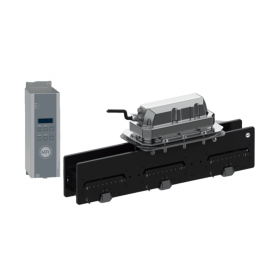
3 Product description Figure 2: Control unit and motor-drive unit 1 Motor-drive unit 2 Connection cable 3 Control unit 3.5 Control unit operating concept You can operate the device using the operating controls on the front panel. Function MENU Call up or closing the parameterization menu AVR AUTO Activate automatic voltage regulation RAISE... - Page 21 3 Product description Function AVR MANUAL Activating manual mode In parameterization menu: Confirm selection EXTERNAL Activate voltage regulation via external con- CONTROL trol unit Table 5: Operating elements Example To set parameter P2.2, delay time T1, proceed as follows: 1. Press to activate manual mode.
-
Page 22: Packaging, Transport And Storage
4 Packaging, transport and storage 4 Packaging, transport and storage 4.1 Packaging The products are sometimes supplied with sealed packaging and sometimes in a dry state, depending on requirements. Sealed packaging surrounds the packaged goods with plastic foil on all sides. -
Page 23: Markings
4 Packaging, transport and storage 4.1.2 Markings The packaging bears a signature with instructions for safe transport and cor- rect storage. The following symbols apply to the shipment of non-hazardous goods. Adherence to these symbols is mandatory. Protect against Fragile Attach lifting Center of mass moisture... -
Page 24: Transportation, Receipt And Handling Of Shipments
4 Packaging, transport and storage 4.2 Transportation, receipt and handling of shipments WARNING Danger of death or severe injury! Danger of death or serious injuries due to tipping or falling load. ► Only transport the crate when closed. ► Do not remove the securing material used in the crate during transport. ►... -
Page 25: Storage Of Shipments
4 Packaging, transport and storage any circumstances install or commission the packaged goods. Either re- dry the dried packaged goods as per the operating instructions, or contact the manufacturer to agree on how to proceed. ▪ Identify the damaged parts. Hidden damage When damages are not determined until unpacking after receipt of the ship- ment (hidden damage), proceed as follows: ▪... -
Page 26: Unpacking Shipments And Checking For Transportation Damages
4 Packaging, transport and storage If the product is installed more than 6 months after delivery, suitable mea- sures must be taken without delay. The following measures can be used: ▪ Correctly regenerate the drying agent and restore the sealed packaging. ▪... -
Page 27: Mounting
5 Mounting 5 Mounting 5.1 Fastening on-load tap-changer to transformer cover Do not paint the surface on the underside of the transformer cover, which later makes contact with the sealing module's O-ring. Only one coating of primer is permitted. 1. Make opening for sealing module and holes for fixing screws in the trans- former cover. - Page 28 5 Mounting 2. Clean sealing surfaces on sealing module and underside of transformer cover. Insert O-ring supplied in sealing module. Figure 4: O-ring NOTICE! Damage to the on-load tap-changer due to incorrect screw con- nections. Guide the on-load tap-changer from below through the opening in the transformer cover and affix horizontally to the transformer cover us- ing 4 screws.
- Page 29 5 Mounting 6. Tighten the screws crosswise with 16 Nm. Ensure that the fastenings are not subject to mechanical stress. Figure 5: Fastening the on-load tap-changer NOTICE! Damage to the on-load tap-changer due to incorrect screw con- nections. Attach the additional seal with 4 screws. Evenly tighten screws crosswise by hand.
-
Page 30: Connecting Tap Winding And On-Load Tap-Changer Take-Off Lead
5 Mounting 8. Tighten the screws crosswise with 9 Nm and then crosswise with 16 Nm. Ensure that the fastenings are not subject to mechanical stress. Figure 6: Additional seal 5.2 Connecting tap winding and on-load tap-changer take-off lead NOTICE Damage to the on-load tap-changer! Mounting mistakes will damage the on-load tap-changer and jeopardize safe operation. - Page 31 5 Mounting Figure 7: Insulation spacings Transformer cover Critical area: Spacing to grounded parts Critical area: Spacing between the phases NOTICE Damage to the on-load tap-changer! Improperly carried out crimp connections jeopardize safe operation. ► Carry out crimp connections in accordance with DIN EN IEC 61238-1-3. ►...
- Page 32 5 Mounting ► Connect the tap-winding connecting leads and on-load tap-changer take- off leads by crimping them onto the connection contacts on the on-load tap-changer and ensure that they are not subject to mechanical stress. Figure 8: Connecting leads and connection contacts ®...
-
Page 33: Mounting Motor-Drive Unit
5 Mounting 5.3 Mounting motor-drive unit Checking the operating position The on-load tap-changer has to be in a defined operating position when mounting the motor-drive unit. DANGER! Check the operating position prior to commissioning the transformer, or ensure that the transformer is de-energized and secured against reconnection. - Page 34 5 Mounting 4. Also check the position of the shaft of the on-load tap-changer: If the pre- vious on-load tap-change operation has been finished correctly, the arrow on the cam disk will point to the arrow in the cover Figure 11: Position of the shaft of the on-load tap-changer ð...
- Page 35 5 Mounting 7. Plug the emergency drive shaft with feather key into the shaft of the on- load tap-changer. Figure 13: Attaching emergency drive shaft 8. Rotate the emergency drive shaft in the direction of the desired operating position using an appropriate tool. Figure 14: Emergency drive shaft actuation ®...
- Page 36 5 Mounting NOTICE! Using the emergency drive shaft, turn for every tap-change op- eration in one direction until one revolution has been completed and the arrow on the cam disk (1) is again pointing to the arrow in the cover (2). Otherwise, the tap-change operation has not been completed correctly, which may result in damage to the on-load tap-changer and transformer.
- Page 37 5 Mounting Mounting motor-drive unit 1. Clean sealing surfaces on the sealing module and underside of the motor- drive unit and check that the O-ring is in the correct position. Figure 18: Cleaning sealing surfaces of the motor-drive unit 2. When mounting for the first time: Remove label with warning. Figure 19: Removing the label ®...
- Page 38 5 Mounting 3. Ensure that the feather key is seated correctly. Figure 20: Checking the feather key is seated correctly 4. Check the position of the motor-drive unit. If mounted incorrectly, the mo- tor-drive unit may be damaged. The feather key of the motor shaft must be facing the mark .
- Page 39 5 Mounting 5. Checking the position of the on-load tap-changer: The mark on the cam disk must be in the marked area on the cover . If not, correct the po- sition as described in the "Actuating motor-drive unit with emergency drive shaft"...
-
Page 40: Connecting Control Unit At The Transformer Manufacturer's Site
5 Mounting 8. Connect the motor-drive unit and transformer cover with a grounding con- ductor. For the ground connection on the motor-drive unit, we recommend using an M8 cable shoe. Figure 24: Connecting the motor-drive unit grounding Perform an automatic adjustment [►Section 7.4.9.1, Page 87] each time the motor-drive unit is replaced or mounted. -
Page 41: Cable Recommendation
5 Mounting 5.4.1 Cable recommendation Please note the following recommendation from Maschinenfabrik Rein- hausen GmbH when wiring the device: Cable Terminal Cable type Conductor cross-sec- Max. length tion Power supply and voltage Unshielded 1.5 mm² with ferrule measurement 2.5 mm² without ferrule Blocking contact Customer messages RS485;... - Page 42 5 Mounting You must connect the power supply circuit with a conductor cross-section of at least 1.5 mm (AWG 16) and protect it with a C10A or B10A type minia- ture circuit breaker. Supply via voltage transformers Electric shock! DANGER If you supply the device via a voltage transformer, the output voltage of the voltage transformer has no bearing on the protective conductor.
- Page 43 5 Mounting Connecting the control unit 1. Connect the 5-wire connection cable of the motor-drive unit to terminal X4 (0.4 Nm). 2. Connect the 2-wire connection cable of the motor-drive unit to terminal X2 (0.5 Nm). Figure 25: Connection cable connection DANGER! Ensure that the connections PE, N, and L are not inter- changed.
-
Page 44: Taking Measurements
5 Mounting 5.5 Taking measurements WARNING Electric shock from incorrect operation! Danger of death or severe injury from electric shock! ► Only take measurements when the transformer is de-energized. ► Only perform tap-change operation with the control unit. ► Tap-change operations initiated by actuation with the emergency drive shaft are not permitted during this test. - Page 45 5 Mounting 2. Press until the desired operating position is reached. ð The new operating position is displayed on the control unit. 3. Carry out the transformer ratio test in all operating positions. ð Once the results have been checked, the transformer ratio test is com- plete.
-
Page 46: Drying The On-Load Tap-Changer
5 Mounting 5.6 Drying the on-load tap-changer NOTICE Damage to the on-load tap-changer, motor-drive unit and con- trol unit. If temperature-sensitive components are dried, they may become damaged. ► Remove motor-drive unit and control unit and do not dry. ► Affix the transport locking plate prior to drying to protect the on-load tap- changer. - Page 47 5 Mounting 4. Remove the motor-drive unit. Figure 28: Removing the motor-drive unit 5. Clean sealing surfaces on sealing module and transport locking plate and check that O-ring is in the correct position. 6. Affix the transport locking plate. Figure 29: Transport locking plate Drying the on-load tap-changer You can dry the on-load tap-changer using one of the following methods.
-
Page 48: Filling Transformer With Oil
5 Mounting ▪ Low-frequency drying in an autoclave ▪ Low-frequency drying in a transformer tank 5.7 Filling transformer with oil For the oil filling of the transformer, use new mineral insulating oil for trans- formers as per IEC 60296 (Specification of unused mineral insulating oils for transformers and switchgear). -
Page 49: Commissioning
6 Commissioning 6 Commissioning 6.1 Commissioning the on-load tap-changer at the transformer manufacturer's site WARNING Flying parts and spraying of hot oil resulting from on-load tap- changer overload! The on-load tap-changer can switch currents of up to twice the rated through-current. - Page 50 6 Commissioning 1. Ensure that the motor-drive unit is positioned correctly: The feather key on the motor-drive unit must be facing the marking Figure 30: Checking the position of the motor-drive unit 2. Ensure that the on-load tap-changer is positioned correctly: The marking on the cam disk must be within the marked range of the cover Figure 31: Checking the position of the on-load tap-changer...
-
Page 51: Performing Trial Tap-Change Operations
6 Commissioning 1. Activate power supply for motor-drive unit and control unit. ð The control unit starts automatically. The LED flashes for 10 s to in- dicate the inrush interlock. After 10 s, this LED lights up blue continu- ously. ð The LED also starts by flashing and then lights up continuously as soon as the internal energy accumulator is fully charged. -
Page 52: Tests On The Transformer
During this time, the control will not accept any tap-change commands. 6.1.2 Tests on the transformer Please contact Maschinenfabrik Reinhausen GmbH (MR) if any aspect of the tests is not clear. 6.1.2.1 Electrical high-voltage tests on the transformer... - Page 53 6 Commissioning It is essential that you ensure only trained, instructed expert personnel who are familiar with and comply with the pertinent safety and technical regula- tions, who are aware of the potential risks, and who consistently use the oc- cupational safety equipment provided to prevent injury and property damage are assigned to perform such a transformer test.
-
Page 54: Resetting Automatic Adjustment
6 Commissioning LED can remain lit for up to 30 minutes after the voltage supply is disconnected. This indicates that the energy accumulator is still charged. This does not represent a hazard during mounting or removing the control unit. 1. Coil the connection cable and secure it on the motor-drive unit. NOTICE! Damage to the control unit. -
Page 55: Transporting Transformer To The Operating Site
NOTICE! Damage to the control unit due to incorrect transportation or storage. Transport control unit in MR packaging used for delivery. Do not transport or store the control unit in the open. 6.3 Commissioning transformer at operating site... -
Page 56: Checking The Correct Position Of The On-Load Tap-Changer And Motor-Drive Unit
6 Commissioning 6.3.1 Checking the correct position of the on-load tap-changer and motor-drive unit DANGER Danger of explosion! An incorrect position of the on-load tap-changer or the motor drive shaft can lead to malfunction and, consequently, to an overload of the on-load tap- changer. -
Page 57: Mounting The Control Unit On An Even Surface
6 Commissioning 6.3.2 Mounting the control unit on an even surface 1. Secure the control unit to the even surface using the fixing brackets pro- vided for this purpose. Note the dimensional drawing in the appendix. 2. Use one of the lower attachment points to ground the control unit housing. To do so, crimp a grounding conductor (minimum cross-section 8 mm²) with a ring-type cable terminal and attach it with washers (contact washer and safety washer) and M6 bolt. - Page 58 6 Commissioning 6.3.3.1 Cable recommendation Please note the following recommendation from Maschinenfabrik Rein- hausen GmbH when wiring the device: Cable Terminal Cable type Conductor cross-sec- Max. length tion Power supply and voltage Unshielded 1.5 mm² with ferrule measurement 2.5 mm² without ferrule Blocking contact Customer messages RS485;...
- Page 59 6 Commissioning 6.3.3.2.2 Wiring requirement of operating site Note the following when wiring the operating site: ▪ Route the connecting leads in grounded metal cable ducts. ▪ Do not route lines which cause interference (for example power lines) and lines susceptible to interference (for example signal lines) in the same ca- ble duct.
- Page 60 6 Commissioning Figure 38: Example: Shield with cable screw connections 6.3.3.3 Requirements for the power supply circuit Power supply during commissioning tests Danger of explosion! DANGER An incorrect position of the on-load tap-changer or the motor drive shaft can lead to malfunction and, consequently, to an overload of the on-load tap- changer.
- Page 61 6 Commissioning Ensure the correct position of the on-load tap-changer: The marking on the cam disk must be in the marked area on the cover Figure 40: Checking the position of the on-load tap-changer Further details: See section "Mounting the motor-drive unit". Power supply during operation After completing the test tap-change operations, you must adjust the power supply for the control unit supplied from a separate power source for the...
- Page 62 6 Commissioning Supply via voltage transformers DANGER Electric shock! If you supply the device via a voltage transformer, the output voltage of the voltage transformer has no bearing on the protective conductor. As a result, protection of the device against electric shock in the event of an error is not guaranteed.
-
Page 63: Switching On Power Supply
6 Commissioning 4. Screw the signal for blocking (e.g. door interlock or temperature blocking) onto the supplied plug connector for X3 with a torque of 0.4 Nm. Tighten the plug connector onto terminal X3 with a torque of 0.4 Nm. 5. Screw the wiring for the "Customer messages" interface (ready/error) to the supplied plug connector for X5 with a torque of 0.4 Nm. -
Page 64: Performing Trial Tap-Change Operations
6 Commissioning To activate the motor-drive unit and control unit, proceed as follows: 1. Activate the power supply for the control unit. ð The control unit starts automatically after a few seconds. The flashes for 10 s to indicate the inrush interlock. After 10 s, this LED lights up blue continuously. -
Page 65: Switching On Medium Voltage
6 Commissioning 2. Use the RAISE/LOWER arrow keys to undertake trial tap-change opera- tions across the entire range of settings. 3. Check that the control unit records and correctly displays every position. Otherwise, carry out automatic adjustment again. The control ensures that the required cooling time of approx. 3 seconds is maintained after each on-load tap-change operation. -
Page 66: Setting Parameters
6 Commissioning To activate the motor-drive unit and control unit, proceed as follows: ► Switch on medium voltage (transformer is idle). ð The control unit starts automatically after a few seconds. The flashes for 10 s to indicate the inrush interlock. After 10 s, this LED lights up blue continuously. -
Page 67: When Operating With Alternative Insulating Liquids: Activating Temperature Blocking
6 Commissioning 5. Press to activate the AVR MANUAL operating mode. ð Automatic voltage regulation has been checked. 6.3.9 When operating with alternative insulating liquids: activating temperature blocking You can operate the on-load tap-changer with alternative insulating fluids upon request. When doing so, you must ensure that switching operations cannot be performed during operation if the transformer's insulating fluid temperature is less than the permissible temperature. - Page 68 6 Commissioning 4. Once the transformer has been switched on, ensure that the inrush cur- rent impulse has subsided. ð On-load tap-change operations can now be undertaken both when idling and under load conditions. ® ® ECOTAP III 30D-24 / MD&C 8209941/00 EN Maschinenfabrik Reinhausen GmbH 2021...
-
Page 69: Operation
7 Operation 7 Operation On-load tap-change operations can be undertaken both manually and auto- matically. You can see the selected operating mode on the LED display on the control unit. In the EXTERNAL CONTROL operating mode, the device executes control commands from an external controller (e.g., ECOTAP® VPD® CON- TROL PRO). -
Page 70: Selecting The Operating Mode
7 Operation NOTICE Damage to the on-load tap-changer! Damage to the on-load tap-changer resulting from switching the on-load tap-changer at impermissible oil temperatures! ► The on-load tap-changer can be operated in the temperature range of the surrounding transformer oil of between –25 °C and +105 °C and in accor- dance with IEC 60214-1 up to +115 °C (during emergency transformer operation in accordance with IEC 60076-7). -
Page 71: Actuating On-Load Tap-Changer Using The Emergency Drive Shaft
7 Operation AVR AUTO auto mode In auto mode, the device executes the tap-change operations automatically, depending on the set control parameters. Observe section "Configuring the control unit" [►Section 7.4, Page 75] for further information on the control parameters. To activate auto mode, proceed as follows: ►... - Page 72 7 Operation DANGER! Risk of fatal injury due to electrical voltage. Ensure that all cables in the working area are de-energized and that the shutdown equip- ment is locked so that it cannot be switched on again. 2. Remove connectors from the terminals X1, X2 and X4 on the control unit. Figure 43: Removing the connection cable 3.
- Page 73 7 Operation 4. Pull the emergency drive shaft out of the bracket in the sealing module. Figure 45: Pulling the emergency drive shaft out of the bracket 5. Plug the emergency drive shaft with feather key into the shaft of the on- load tap-changer.
- Page 74 7 Operation NOTICE! Damage to the on-load tap-changer due to a tap-change opera- tion not being completed correctly. Turn the emergency drive shaft using a suitable tool in one direction until reaching one complete revolution and the arrow on the cam disk is again facing the arrow in the cover- TICE! .
-
Page 75: Configuring The Control Unit
7 Operation 8. Mount the motor-drive unit. 9. Connect the connectors to the terminals X4, X2 and X1 on the control unit. 7.4 Configuring the control unit This chapter describes how to configure the control unit. Settings are only saved once the parameterization menu is exited via the key. - Page 76 7 Operation Figure 50: Regulation function response 1 + B%: Upper limit : Desired value desired 3 - B%: Lower limit 4 Set delay time T : Measured voltage 6 B%: Tolerance bandwidth actual is outside the bandwidth. De- is back within the bandwidth actual actual lay time T starts.
- Page 77 7 Operation 7.4.1.2 Bandwidth B1 (P2.1) You can use this parameter to set the maximum permissible deviation in measured voltage U from the desired value U . The following section actual desired describes how you determine and set the bandwidth. Determining bandwidth In order to set the correct value, the transformer step voltage and nominal voltage must be known.
- Page 78 7 Operation 2. Press to confirm the selection. ð 3. Press to confirm the selection. 4. Press to select the desired value. 5. Press to confirm the selection. 6. Press to save the setting. 7.4.1.3 Delay time T1 (P2.2) The delay time T1 delays the issuing of a tap-change command for a de- fined period.
- Page 79 7 Operation To set the B2 bandwidth, proceed as follows: ü The AVR MANUAL operating mode is active. 1. Press > until the desired parameter is displayed. ð 2. Press to confirm the selection. ð 3. Press to confirm the selection. 4.
-
Page 80: Voltage Blocking (P4)
7 Operation 7.4.2 Voltage blocking (P4) You can use voltage blocking to define limit values for blocking the auto- matic voltage regulation (AVR AUTO). This allows you to avoid unnecessary tap-change operations in the event of strong voltage changes in the mains. ▪... -
Page 81: Blocking Function (P5)
7 Operation 6. Press to confirm the selection. 7. Press to save the setting. 7.4.3 Blocking function (P5) The control unit is equipped with a blocking contact. You can use this to con- nect a door contact switch or a temperature sensor, for example. If you would like to use a temperature sensor, the temperature sensor must make a signal in the form of a floating contact available. - Page 82 7 Operation You can only use the function "Target position for loss of voltage" in the op- erating modes AVR AUTO and EXTERNAL CONTROL. Damage to the on-load tap-changer and transformer! NOTICE The inrush interlock is not active when switching to the target tap position. If the voltage returns while switching to the target tap position, the on-load tap-changer and transformer may be damaged.
-
Page 83: Number Of Operating Positions (P7)
7 Operation To activate or deactivate the "Target position for loss of voltage" function, proceed as follows: ü The AVR MANUAL operating mode is active. 1. Press > until the desired parameter is displayed. ð 2. Press to confirm the selection. 3. -
Page 84: Regulating Range (P8)
7 Operation 5. Press to save the setting. 7.4.6 Regulating range (P8) You can limit the permissible regulating range as necessary. Here, you can set the lowest operating position and the highest operating position. The limited regulating range applies to all operating modes. You can, how- ever, move to an operating position outside of the permissible regulating range via the "Target position for loss of voltage"... -
Page 85: Remote Behavior (P9)
7 Operation 4. Press to confirm the selection. 5. Press to select the desired value. 6. Press to confirm the selection. 7. Press to save the setting. 7.4.7 Remote behavior (P9) You can use this parameter to set the remote behavior of the device in con- nection with the ECOTAP®... - Page 86 7 Operation 7.4.8.1 Setting the password (P10.1) You can use this parameter to set the password (maximum 3 characters, factory setting 0). To do so, proceed as follows: ü The AVR MANUAL operating mode is active. 1. Press > until the desired parameter is displayed. ð...
-
Page 87: Adjustment (F1)
7 Operation 7. Press to save the setting. 7.4.8.3 Entering password (C2) If you have activated the password protection function, you must enter the password to unblock the device and to be able to call up the parameteriza- tion menu. To do so, proceed as follows: ü... - Page 88 7 Operation 3. Press until the desired parameter is displayed. ð 4. Press to confirm the selection. ð 5. Press until code 3 is displayed. ð 6. Press to confirm the selection. ð Automatic adjustment starts. ð Once automatic adjustment is complete, the on-load tap-changer is in the middle operating position.
-
Page 89: Reading Remaining Life (F2)
7 Operation 6. Repeat step 5 until the lowest tap position (Pos. 1) has been reached. ð Once the lowest tap position (Pos. 1) has been reached, the display switches between operations counter, tap position and measured volt- age. ð Manual adjustment is complete. 7.4.9.3 Manual adjustment n+1 (F1.3) You can use this function to perform a manual adjustment of the on-load tap- changer starting from the current tap position through to the highest tap posi-... -
Page 90: Led Function Test (F3)
7 Operation If the remaining life is less than 5(%), contact Maschinenfabrik Reinhausen GmbH's Technical Service department. For functional reasons, the remaining life drops more quickly at the begin- ning of the product life cycle and levels out as the operating time increases. The typical progression of the remaining life is shown below: 100 % 20 %... -
Page 91: Software Update (F4)
7 Operation 2. Press to confirm the selection. ð All display elements on the front of the control unit light up. 3. Press to exit the display. 4. Press to leave the parameterization menu. 7.4.12 Software update (F4) You can use this function to perform software updates. Contact Maschinen- fabrik Reinhausen GmbH if you have any problems when operating the de- vice. -
Page 92: Read Out Software Version (F6)
7 Operation 7.4.14 Read out software version (F6) To read out the software version, proceed as follows: ü The AVR MANUAL operating mode is active. > Press until the desired function is displayed. ð 2. Press to confirm the selection. ð... -
Page 93: Reset To Factory Setting (F8)
7 Operation 7.4.15.2 Customer message for event message E2 (F7.2) With this function, you can set whether the event message E2 Remote con- trol is to be reported via the customer messages interface Ready/Error (ter- minal X5). You can select the following options: ▪... -
Page 94: Display Control Parameters (F9)
7 Operation 6. Press to leave the parameterization menu. 7.4.17 Display control parameters (F9) You can use this function to check the set values of the device. Here, the de- vice successively displays the parameter designation and the set values of the following parameters and functions: ▪... - Page 95 7 Operation To display the event memory, proceed as follows: ü The AVR MANUAL operating mode is active. 1. Press > repeatedly until the first memory slot in the event mem- ory is displayed. ð 2. Press to select the desired memory slot. ð...
-
Page 96: Control System Protocol
8 Control system protocol 8 Control system protocol 8.1 Modbus RTU Parameters The device uses the Modbus RTU (server) control system protocol with the following parameters: Parameter Modbus RTU Transmission format Serial interface RS485 Baud rate 38,400 baud Modbus address Number of data bits Parity Even... -
Page 97: Data Points (Single Inquiry)
8 Control system protocol 8.4 Data points (single inquiry) 8.4.1 Coils Address Name Coil status EXTERNAL CONTROL R = read / W = write CONTROL PRO Others Change tap position raise 1 = raise Change tap position lower 1 = lower Blocking activation P5 level 1 1 = active (level 1) F5 command inverted... -
Page 98: Input Register
8 Control system protocol Address Name Coil status EXTERNAL CONTROL R = read / W = write CONTROL PRO Others E6.3 Tap change command cannot be performed 1 = active E7. Correct positioning not possible 1 = active E7. Correct positioning not possible 1 = active Blocking contact 0 = door open... -
Page 99: Holding Register
8 Control system protocol 8.4.4 Holding register Address Name Unit Decimal EXTERNAL CONTROL places R = read / W = write CONTROL PRO Others Operating mode ▪ 1 = AVR AUTO ▪ 2 = AVR MANUAL ▪ 3 = EXTERNAL CONTROL Tap position Operations counter (MSB) Operations counter (LSB) -
Page 100: Data Points (Collective Inquiry)
8 Control system protocol 8.5 Data points (collective inquiry) Address Range Parameter Description Type Value Others No connection to EXTERNAL CON- 0 = ok TROL 1 = error EXTERNAL CONTROL command 0 = ok could not be performed 1 = error E3.1 Error in connection between control 0 = ok... - Page 101 0…65 535 month (21, high-byte) year (22, low-byte) 0…15 Firmware version (2/2) UINT16 0…65 535 day (day 23, low-byte) 0…15 MR serial number MD&C (1/2) UINT16 0…65 535 0…15 MR serial number MD&C (2/2) UINT16 0…65 535 0…15 MR serial number OLTC (1/2) UINT16 0…65 535...
- Page 102 8 Control system protocol With the command "Multiple switching operations" up to 3 successive switching operations can be executed without a regular pause of 3 seconds. This is followed by a cooling period of ▪ 3 seconds for 1 on-load tap-change operation ▪...
-
Page 103: Fault Elimination
9 Fault elimination 9 Fault elimination The transformer can be operated in the current operating position safely de- spite the red signal light. Further switching operations are blocked. 9.1 General faults Characteristics/details Cause Remedy No function No voltage supply Check the voltage supply. Device-internal fuse (F1) tripped Check fuse (F1) and replace if necessary. -
Page 104: Other Faults
In the event of faults on the on-load tap-changer, motor-drive unit, or control unit which cannot be easily corrected on site, please inform your authorized MR representative, the transformer manufacturer or contact Maschinenfabrik Reinhausen GmbH (MR) directly. Please have the following data ready: ▪... -
Page 105: Maintenance
10 Maintenance 10 Maintenance DANGER Electric shock! An energized transformer could cause death or serious injuries. ► Switch off transformer on high and low-voltage side. ► Lock transformer to prevent unintentional restart. ► Ensure that everything is de-energized. ► Visibly connect all transformer terminals to ground (grounding leads, grounding disconnectors) and short circuit them. -
Page 106: Checking The Control Unit
10 Maintenance 10.1.2 Checking the control unit 1. Check remaining life of the energy accumulator [►Section 10.1.4, Page 106]. ð If the remaining life is less than 20(%), contact Maschinenfabrik Rein- hausen GmbH's Technical Service department. 2. Check the function of the LEDs [►Section 10.1.5, Page 107]. 10.1.3 Read out software version (F6) To read out the software version, proceed as follows: ü... -
Page 107: Led Function Test (F3)
10 Maintenance For functional reasons, the remaining life drops more quickly at the begin- ning of the product life cycle and levels out as the operating time increases. The typical progression of the remaining life is shown below: 100 % 20 % Time Figure 53: Typical progression of the remaining life... -
Page 108: Checking The Temperature Blocking
10 Maintenance 4. Press to leave the parameterization menu. 10.1.6 Checking the temperature blocking If you operate the on-load tap-changer with alternative insulating fluids, you must check the function of the temperature blocking [►Section 6.3.9, Page 67]. To do so, proceed as follows: ü... -
Page 109: Maintenance
10 Maintenance 10.2 Maintenance The ECOTAP® VPD® on-load tap-changer and ECOTAP® VPD® MD&C motor-drive unit are maintenance-free. Interval Action After 500,000 operations Replacing the on-load tap-changer: Con- tact the Maschinenfabrik Reinhausen Technical Service department for this. After a maximum of 20 years Replace the control unit. Contact the Maschinenfabrik Reinhausen Technical Service department for this. -
Page 110: Messages
EXTERNAL CONTROL is connected correctly. TROL Check that the EXTERNAL CONTROL is working correctly. Follow the corresponding operating instructions when doing If the error is still present, contact MR. Info EXTERNAL CON- Check the EXTERNAL CONTROL operating mode setting. - Page 111 E3.3 drive unit Has the factory-set wiring on X2 or X4 been changed? If E3.4 yes, restore to original status. If the error is still present, contact MR. E4.1 Error Automatic adjust- Carry out automatic adjustment (again). ment not under- taken or incorrect.
-
Page 112: Overview Of Parameters
12 Overview of parameters 12 Overview of parameters Parameter Setting range Factory settings Current settings P1: Desired voltage 84…266 V 225 V P2: Normal regulation P2.1: Bandwidth B1 0.5…8 % P2.2: Delay time T1 5...1800 s 10 s P3: Fast regulation P3.1: Bandwidth B2 3%...9%; off P3.2: Delay time T2 2 s…(T1 - 1 s / 5 s) P4: Voltage blocking... - Page 113 12 Overview of parameters Parameter Setting range Factory settings Current settings F6: Read out software version F7: Error relay F7.1: Error relay E1 0 = inactive, 1 = active 1 = active F7.2: Error relay E2 0 = inactive, 1 = active 1 = active F8: Factory settings F9: Display control parameters...
-
Page 114: Disposal
13 Disposal 13 Disposal For disposal, observe the national requirements applicable in the country of use. If you have any questions about disassembly and disposal, please contact Maschinenfabrik Reinhausen GmbH's Technical Service department. ® ® ECOTAP III 30D-24 / MD&C 8209941/00 EN Maschinenfabrik Reinhausen GmbH 2021... -
Page 115: Technical Data
14 Technical data 14 Technical data 14.1 On-load tap-changer type designation The designation of a particular on-load tap-changer model depends on vari- ous features, hence ensuring an unmistakable and non-interchangeable on- load tap-changer designation. 14.1.1 ECOTAP® VPD on-load tap-changer designation Type designation ECOTAP®... -
Page 116: Technical Data For The On-Load Tap-Changer
14 Technical data 14.2 Technical data for the on-load tap-changer Type ECOTAP® … VPD® III 30 Number of phases Application At any point in the winding Permitted transformer types Free breathing with oil conservator Entirely oil-filled hermetically sealed transformers (without gas cushion) Free breathing with air cushion only in combination with a spe- cial variant of the ECOTAP VPD (on request) Maximum rated through-current... -
Page 117: Step Capacity Diagram
14 Technical data 14.3 Step capacity diagram Figure 54: Step capacity diagram for ECOTAP® VPD® ® ® Maschinenfabrik Reinhausen GmbH 2021 8209941/00 EN ECOTAP III 30D-24 / MD&C... -
Page 118: Permitted Voltage Stresses
14 Technical data 14.4 Permitted voltage stresses The specifications in this section only apply to use in mineral insulating oil in accordance with IEC 60296. Data for alternative insulating fluids is available on request. This section describes the permitted voltage stresses on the tap winding and on-load tap-changer. - Page 119 14 Technical data ® Insulation distances for an ECOTAP VPD® III without change-over selector ® Figure 55: ECOTAP VPD III without change-over selector Abbreviations for the rated insulation level: Abbreviations for the rated insulation level: Full wave lightning impulse (kV, 1.2/50 μs) Chopped wave lightning impulse (kV, 1.2/50/3 µs) Applied voltage (kV, 50 Hz, 1 min) Table 29: Abbreviations for the rated insulation level: Rated insulation level (voltage magnitudes for delta applications in kV)
- Page 120 14 Technical data Highest voltage for equipment: = 24 kV Insulation dis- Voltage waveform Without change-over selector tance LI 1.2/50 µs LIC 1.2/50/3…6 µs AC 50 Hz, 1 min LI 1.2/50 µs LIC 1.2/50/3…6 µs AC 50 Hz, 1 min LI 1.2/50 µs LIC 1.2/50/3…6 µs AC 50 Hz, 1 min Table 30: Rated insulation level (voltage magnitudes for delta applications in kV) ®...
-
Page 121: Limit Values For Dielectric Strength And Water Content Of On-Load Tap-Changer Oil
14 Technical data 14.5 Limit values for dielectric strength and water content of on- load tap-changer oil The following table provides the limit values for dielectric strength (measured in accordance with IEC 60156) and water content (measured in accordance with IEC 60814) of the on-load tap-changer oil for the ECOTAP® VPD® on- load tap-changer. -
Page 122: Technical Data For The Motor-Drive Unit
14 Technical data Contamination level Installation site Standard: Indoors Control cabinet for outdoor use: Outdoors Control cabinet for indoor use version with ECOTAP® VPD® CONTROL PRO: Indoors The control cabinet must be protected against direct sunlight. Table 33: Permissible ambient conditions Interfaces Interface Description... -
Page 123: Drawings
15 Drawings 15 Drawings 15.1 Information on the drawings in the appendix The drawings listed in this section are examples. The delivered product may deviate from these examples. The drawings that you receive with the order confirmation are definitive. 15.2 Dimensional drawings ®... -
Page 127: High-Voltage Connection Diagrams
15 Drawings 15.3 High-voltage connection diagrams ® ® Maschinenfabrik Reinhausen GmbH 2021 8209941/00 EN ECOTAP III 30D-24 / MD&C... -
Page 130: Dimensional Diagram For Control Unit (10014680)
15 Drawings 15.4 Dimensional diagram for control unit (10014680) ® ® ECOTAP III 30D-24 / MD&C 8209941/00 EN Maschinenfabrik Reinhausen GmbH 2021... - Page 132 Maschinenfabrik Reinhausen GmbH Falkensteinstrasse 8 93059 Regensburg +49 (0)941 4090-0 sales@reinhausen.com www.reinhausen.com ® ® 8209941/00 EN - ECOTAP III 30D-24 / MD&C - F0402200 - 07/21 - Maschinenfabrik Reinhausen GmbH 2021 THE POWER BEHIND POWER.
Need help?
Do you have a question about the ECOTAP VPD 3 30D-24 and is the answer not in the manual?
Questions and answers
Please help me ,I want to buy your products