
Related Manuals for MR VACUTAP VV


Summary of Contents for MR VACUTAP VV
- Page 1 THE POWER BEHIND POWER. Installation and commissioning instructions VACUTAP® VV®. On-load tap-changer 4349322/03 EN...
- Page 2 © All rights reserved by Maschinenfabrik Reinhausen Dissemination and reproduction of this document and use and disclosure of its content are strictly prohibited unless expressly permitted. Infringements will result in liability for compensation. All rights reserved in the event of the granting of patents, utility models or designs.
-
Page 3: Table Of Contents
Table of contents 1 Introduction ..........5 5.2 Installing the on-load tap-changer in the 1.1 Manufacturer ..............5 transformer (standard version) ......33 1.2 Completeness ............... 5 5.2.1 Fastening on-load tap-changer to 1.3 Safekeeping ..............5 transformer cover ......... 33 1.4 Notation conventions .......... - Page 4 5.4 Fitting protective devices and drive 8.2 Technical data for protective relay ......156 components.............. 71 8.3 Special models of protective relay......158 5.4.1 Electrically connecting the temperature 8.3.1 Protective relay with CO change-over sensor.............. 71 contact as tripping switch ......158 5.4.2 Connecting tap-change supervisory 8.3.2 Protective relay with several dry-reed control .............
-
Page 5: Introduction
Germany Tel.: +49 941 4090-0 E-mail: sales@reinhausen.com Internet: www.reinhausen.com MR Reinhausen customer portal: https://portal.reinhausen.com Further information on the product and copies of this technical file are available from this address if required. 1.2 Completeness This technical file is incomplete without the supporting documents. -
Page 6: Notation Conventions
1.4 Notation conventions 1.4.1 Hazard communication system Warnings in this technical file are displayed as follows. 1.4.1.1 Warning relating to section Warnings relating to sections refer to entire chapters or sections, sub-sections or several paragraphs within this technical file. Warnings relating to sections use the following format: WARNING Type of danger! - Page 7 Aim of action Requirements (optional). Step 1 of 1. Result of step (optional). Result of action (optional). Multi-step instructions Instructions which consist of several process steps are structured as follows: Aim of action Requirements (optional). 1. Step 1. Result of step (optional). 2.
-
Page 8: Safety
2 Safety – Read this technical file through to familiarize yourself with the product. – This technical file is a part of the product. – Read and observe the safety instructions provided in this chapter. – Read and observe the warnings in this technical file in order to avoid func- tion-related dangers. -
Page 9: Inappropriate Use
2.2 Inappropriate use Use is considered inappropriate if the product is used in a way other than as de- scribed in the "Appropriate use" section. In addition, observe the following: Prohibited electrical operating conditions All operating conditions that do not comply with the design data in accordance with the order confirmation are prohibited. -
Page 10: Personal Protective Equipment
Explosion protection Highly flammable or explosive gases, vapors and dusts can cause serious explo- sions and fire. This increases the danger to life and limb. – Do not install, operate or perform maintenance work on the product in areas where a risk of explosion is present. Safety markings Warning signs and safety information plates are safety markings on the prod- uct. -
Page 11: Personnel Qualification
Protective clothing Close-fitting work clothing with a low tearing strength, with tight sleeves and with no protruding parts. It mainly serves to protect the wearer against being caught by moving machine parts. Safety shoes To protect against falling heavy objects and slipping on slip- pery surfaces. - Page 12 Authorized personnel Authorized personnel are trained by Maschinenfabrik Reinhausen GmbH to carry out special maintenance. Safety 4349322/03 EN...
-
Page 13: Product Description
3 Product description 3.1 Scope of delivery The product is packaged with protection against moisture and is usually deliv- ered as follows: – On-load tap-changer – Motor-drive unit – Drive shaft with coupling parts and bevel gear – Protective device –... -
Page 14: Setup/Models
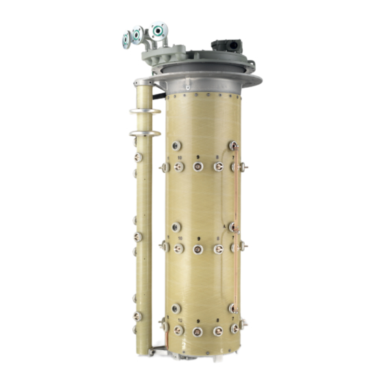
Figure 1: System overview of on-load tap-changer, transformer 1 Transformer tank 6 Gear unit 2 Motor-drive unit 7 On-load tap-changer 3 Vertical drive shaft 8 Protective relay 4 Bevel gear 9 Oil conservator 5 Horizontal drive shaft 10 Active part 3.2.2 Setup/models The following drawing shows the main components of the on-load tap-changer. - Page 15 You will find a detailed drawing of the on-load tap-changer in the "Drawings [►Section 9, Page 162]" section. Figure 2: On-load tap-changer 1 Upper gear unit 2 On-load tap-changer head 3 Supporting flange 4 Connection contact 5 Oil compartment 6 Change-over selector 7 Pipe bend 8 Rupture disk 3.2.2.1 Pipe connections...
-
Page 16: Nameplate And Serial Number
Pipe connection S The pipe bend on pipe connection S features a vent screw and can be con- nected to a pipe that ends with a drain valve on the side of the transformer tank at operating height. If the on-load tap-changer is fitted with an oil suction pipe, the on-load tap-changer can be completely emptied via pipe connection S. - Page 17 The protective relay is a component of an on-load tap-changer filled with insu- lating fluid and its properties conform to the respective applicable version of IEC publication 60214-1. Diverter switch operations at rated switching capacity or at permissible overload will not cause the protective relay to trip. The protective relay responds to flow, not to gas accumulated in the pro- tective relay.
- Page 18 View from above Figure 7: Protective relay RS 2001 1 Gasket 2 Potential tie-in 3 Terminal box cover 4 Slotted head screw for potential tie-in 5 OPERATION (reset) test button 6 Slotted head screw for protective cover 7 OFF (test tripping) test button 8 Cable gland 9 Protective cover 10 Dummy plug...
- Page 19 The pressure monitoring device responds to large pressure increases faster than the protective relay. The protective relay is part of the standard MR protec- tion system and comes as standard. Additional use of a pressure monitoring device also requires installation of the provided protective relay.
- Page 20 The housing and the cover cap of the pressure monitoring device consist of lightweight, corrosion-resistant metal. Figure 9: Snap-action switch and pressure measuring element 1 Snap-action switch 2 Pressure measuring element Figure 10: Pressure monitoring device with cover cap and ventilation 1 Ventilation 2 Cover cap Product description 4349322/03 EN...
- Page 21 3.2.4.4 Pressure relief device MPREC® ® On request, MR will supply a pre-fitted MPREC pressure relief device in place of the rupture disk. This device responds to a defined overpressure in the oil com- partment of the on-load tap-changer.
-
Page 22: Drive Shaft
3.3 Drive shaft 3.3.1 Function description The drive shaft is the mechanical connection between the drive and the on-load tap-changer/de-energized tap-changer. The bevel gear changes the direction from vertical to horizontal. Accordingly, the vertical drive shaft has to be mounted between drive and bevel gear, and the horizontal drive shaft between bevel gear and on-load tap- changer or de-energized tap-changer. - Page 23 3.3.2.1 Drive shaft without cardan joint and without insulator Figure 12: Drive shaft without cardan joint and without insulator (= standard version) Configuration V 1 min Intermediate bearing Middle of hand crank – middle of bevel 536 mm When the maximum value of gear (maximum permissible axial offset 2472 mm is exceeded, it is 2°)
- Page 24 3.3.2.2 Drive shaft without cardan joint and with insulator Figure 13: Drive shaft without cardan joint and with insulator (= special model) Configuration V 1 min Intermediate bearing Middle of hand crank – middle of bevel 706 mm When the maximum value of gear (maximum permissible axial offset 2472 mm is exceeded, it is 2°)
- Page 25 3.3.2.3 Drive shaft with cardan joints, without insulator Figure 14: Drive shaft with cardan joints, without insulator (= special model) Configuration V 1 min [mm] Intermediate bearing for [mm] Middle of hand crank – middle of bevel V 1 > 2564 gear (maximum permissible axial offset 20°) 4349322/03 EN Product description ...
- Page 26 3.3.2.4 Drive shaft with cardan joints, with insulator Figure 15: Drive shaft with cardan joints, with insulator (= special model) Configuration V 1 min [mm] Intermediate bearing for [mm] Middle of hand crank – middle of bevel V 1 > 2772 gear (maximum permissible axial offset 20°) Product description 4349322/03 EN...
-
Page 27: Packaging, Transport And Storage
4 Packaging, transport and storage 4.1 Packaging The products are sometimes supplied with sealed packaging and sometimes in a dry state, depending on requirements. Sealed packaging surrounds the packaged goods with plastic foil on all sides. Products that have also been dried are identified by a yellow label on the sealed packaging. -
Page 28: Markings
4.1.2 Markings The packaging bears a signature with instructions for safe transport and correct storage. The following symbols apply to the shipment of non-hazardous goods. Adherence to these symbols is mandatory. Protect against Fragile Attach lifting Center of mass moisture gear here Table 3: Shipping pictograms Packaging, transport and storage 4349322/03 EN... -
Page 29: Transportation, Receipt And Handling Of Shipments
4.2 Transportation, receipt and handling of shipments WARNING Danger of death or severe injury! Danger of death or serious injuries due to tipping or falling load. Only transport the crate when closed. Do not remove the securing material used in the crate during transport. If the product is delivered on a pallet, secure it sufficiently. -
Page 30: Storage Of Shipments
With hidden damage, it is very hard to make the transportation company (or other responsible party) liable. Any insurance claims for such damages can only be successful if relevant provisions are expressly included in the insurance terms and conditions. 4.3 Storage of shipments Packaged goods dried by Maschinenfabrik Reinhausen Upon receipt of the shipment, immediately remove the packaged goods dried by Maschinenfabrik Reinhausen from the sealed packaging and store air-tight in... -
Page 31: Mounting
5 Mounting WARNING Risk of crushing! When the on-load tap-changer undertakes a tap-change operation, compo- nents – some of which are freely accessible – move on the selector, change- over selector, and potential connection unit. Reaching into the selector, change-over selector, or potential connection unit during a tap-change opera- tion may result in serious injuries. -
Page 32: Fitting Stud Bolts On Mounting Flange
5.1.2 Fitting stud bolts on mounting flange To attach the stud bolts to the mounting flange, use a tracing template. This can be provided upon request free of charge for the initial installation of the on- load tap-changer. 1. Place tracing template on mounting flange and use the four markings to align. -
Page 33: Installing The On-Load Tap-Changer In The Transformer (Standard Version)
5.2 Installing the on-load tap-changer in the transformer (standard version) 5.2.1 Fastening on-load tap-changer to transformer cover Note that only on-load tap-changers with an unscrewed supporting flange can be fitted in a transformer with the standard design. 5.2.1.1 Lifting top part of on-load tap-changer head off supporting flange (bottom part) NOTICE Damage to the on-load tap-changer! - Page 34 6. Remove on-load tap-changer head cover. Figure 19: On-load tap-changer head cover 7. For design with oil suction pipe, loosen screw connection of R3/4" oil suction pipe. Check for leaks. Figure 20: Oil suction pipe 8. Remove bolts and locking washers between top part of on-load tap-changer head and supporting flange.
- Page 35 9. Lift top part of on-load tap-changer head off supporting flange. Figure 22: On-load tap-changer head 5.2.1.2 Positioning the top part of the on-load tap-changer head on the transformer cover 1. Clean sealing surfaces on mounting flange and on-load tap-changer head, place oil-resistant gasket on mounting flange.
- Page 36 2. Position top part of on-load tap-changer head on mounting flange. Figure 24: On-load tap-changer head For design without oil suction pipe, the on-load tap-changer head can be turned towards the supporting flange in 15° steps. For design with oil suc- tion pipe, turning at 15°...
- Page 37 changer head. Under no circumstances should the on-load tap-changer be lifted up with the fixing bolts. Ensure that all supporting flange stud bolts go easily through the mounting holes of the on-load tap-changer head. Figure 25: On-load tap-changer 2. Screw the top part to the bottom part of the on-load tap-changer head. Figure 26: On-load tap-changer head 3.
-
Page 38: Connecting The Tap Winding And On-Load Tap-Changer Take-Off Lead
4. Screw the on-load tap-changer head to the mounting flange. The tightening torque depends on the screw connection elements used. Figure 28: On-load tap-changer head 5. Place on-load tap-changer head cover on on-load tap-changer head and se- cure. Figure 29: On-load tap-changer head cover 5.2.2 Connecting the tap winding and on-load tap-changer take-off lead NOTICE... - Page 39 The designations of the on-load tap-changer's connection contacts are shown in the connection diagram. The connection contacts are provided with vertical through-holes (11 mm diameter for M10 screws, see appendix). 1. Connect tap winding and on-load tap-changer take-off lead in accordance with the connection diagram included with the delivery.
-
Page 40: Performing Transformer Ratio Test Before Drying
5.2.3 Performing transformer ratio test before drying NOTICE Damage to the on-load tap-changer! Damage to the on-load tap-changer due to transformer ratio test being incor- rectly performed. Do not perform more than 250 tap-change operations on the on-load tap- changer. If more than 250 tap-change operations are to be performed, completely fill the oil compartment with insulating fluid and lubricate slid- ing surfaces of contacts on the selector and selector gear with insulating fluid. -
Page 41: Drying On-Load Tap-Changer In Autoclave
Within 10 hours of drying, seal off oil compartment with on-load tap- changer head cover. Dry on-load tap-changer in accordance with the following instructions to ensure the dielectric values assured by MR for the on-load tap-changer. If drying in an autoclave, the following methods are possible: –... - Page 42 NOTICE Damage to the on-load tap-changer! Small parts in the oil compartment may block the diverter switch insert, thereby damaging the on-load tap-changer. Ensure that parts do not fall into the oil compartment. Check that all small parts are accounted for. 1.
- Page 43 5.2.5.1.4 Securing on-load tap-changer head cover NOTICE Damage to the on-load tap-changer! A missing or damaged o-ring as well as unclean sealing surfaces lead to insu- lating fluid escaping and therefore to damage to the on-load tap-changer. Ensure that the o-ring is positioned untwisted in the on-load tap-changer head cover.
- Page 44 5.2.5.2.2 Removing on-load tap-changer head cover WARNING Danger of explosion! Explosive gases under the on-load tap-changer head cover can deflagrate or explode and result in severe injury or death. Ensure that there are no ignition sources such as open flames, hot surfaces or sparks (e.g.
- Page 45 Figure 36: Kerosene drain plug 5.2.5.2.4 Drying the on-load tap-changer NOTICE Damage to the on-load tap-changer head cover and on-load tap- changer accessories. Both the on-load tap-changer head cover and the on-load tap-changer acces- sories will become damaged if they are dried. Never dry the on-load tap-changer head cover or the following accessories: motor-drive unit, drive shaft, protective relay, pressure monitoring device, pressure relief device, bevel gear, sensors such as temperature and humid-...
-
Page 46: Drying On-Load Tap-Changer In Transformer Tank
5.2.6 Drying on-load tap-changer in transformer tank Dry on-load tap-changer in accordance with the following instructions to ensure the dielectric values assured by MR on the on-load tap-changer. If you want to dry the on-load tap-changer in the transformer tank, fully assem- ble the transformer first and then undertake drying. - Page 47 1. Establish a connecting lead between either connections E2 and Q or connec- tions E2 and R on the on-load tap-changer head. 2. Seal off unused pipe connections and pipe bends with a suitable blank cover. Figure 38: Connecting lead Vacuum-drying in the transformer tank 1.
-
Page 48: Filling The Oil Compartment Of The On-Load Tap-Changer With Insulating Fluid
4. Connect pipe connections R and Q of on-load tap-changer head to the kerosene vapor lead using one shared lead. Figure 40: Kerosene vapor lead 5. Seal off unused pipe connections and pipe bends with a suitable blank cover. Vapor-phase drying in the transformer tank 1. - Page 49 After drying, completely fill the oil compartment (diverter switch insert fitted) with insulating fluid again as soon as possible so that an impermissible amount of humidity is not absorbed from the surroundings. 1. Establish a connecting lead between pipe connection E2 and one of the pipe connections R, S or Q to ensure equal pressure in the oil compartment and transformer during evacuation.
-
Page 50: Performing Transformer Ratio Test After Drying
5.2.8 Performing transformer ratio test after drying NOTICE Damage to the on-load tap-changer! Damage to the on-load tap-changer due to transformer ratio test being incor- rectly performed. Ensure that the selector / de-energized tap changer is fully immersed in the insulating fluid and that the oil compartment of the on-load tap-changer is completely filled with insulating fluid. -
Page 51: Installing On-Load Tap-Changer In Transformer (Bell-Type Tank Version)
5.3 Installing on-load tap-changer in transformer (bell-type tank version) 5.3.1 Inserting on-load tap-changer into supporting structure 1. Remove the red-colored packaging material and the transport material from the on-load tap-changer. NOTICE! Tensile forces can lead to damage and malfunctions on the on-load tap-changer. -
Page 52: Connecting The Tap Winding And On-Load Tap-Changer Take-Off Lead
5.3.2 Connecting the tap winding and on-load tap-changer take-off lead NOTICE Damage to the on-load tap-changer! Connecting leads which place mechanical strain on the on-load tap-changer will damage the on-load tap-changer! Establish and secure connections with care. Do not twist connection contacts. Connect connecting leads without warping or deforming. -
Page 53: Performing Transformer Ratio Test Before Drying
5.3.3 Performing transformer ratio test before drying NOTICE Damage to the on-load tap-changer! Damage to the on-load tap-changer due to transformer ratio test being incor- rectly performed. Do not perform more than 250 tap-change operations on the on-load tap- changer. If more than 250 tap-change operations are to be performed, completely fill the oil compartment with insulating fluid and lubricate slid- ing surfaces of contacts on the selector and selector gear with insulating fluid. -
Page 54: Drying On-Load Tap-Changer In Autoclave
Within 10 hours of drying, seal off oil compartment with on-load tap- changer head cover. Dry on-load tap-changer in accordance with the following instructions to ensure the dielectric values assured by MR for the on-load tap-changer. If drying in an autoclave, the following methods are possible: –... - Page 55 NOTICE Damage to the on-load tap-changer! Small parts in the oil compartment may block the diverter switch insert, thereby damaging the on-load tap-changer. Ensure that parts do not fall into the oil compartment. Check that all small parts are accounted for. 1.
- Page 56 5.3.5.1.4 Securing on-load tap-changer head cover NOTICE Damage to the on-load tap-changer! A missing or damaged o-ring as well as unclean sealing surfaces lead to insu- lating fluid escaping and therefore to damage to the on-load tap-changer. Ensure that the o-ring is positioned untwisted in the on-load tap-changer head cover.
- Page 57 5.3.5.2.2 Removing on-load tap-changer head cover WARNING Danger of explosion! Explosive gases under the on-load tap-changer head cover can deflagrate or explode and result in severe injury or death. Ensure that there are no ignition sources such as open flames, hot surfaces or sparks (e.g.
- Page 58 Figure 51: Kerosene drain plug 5.3.5.2.4 Drying the on-load tap-changer NOTICE Damage to the on-load tap-changer head cover and on-load tap- changer accessories. Both the on-load tap-changer head cover and the on-load tap-changer acces- sories will become damaged if they are dried. Never dry the on-load tap-changer head cover or the following accessories: motor-drive unit, drive shaft, protective relay, pressure monitoring device, pressure relief device, bevel gear, sensors such as temperature and humid-...
-
Page 59: Lifting Top Part Of On-Load Tap-Changer Head Off Supporting Flange (Bottom Part)
Place on-load tap-changer head cover on on-load tap-changer head and se- cure. Figure 52: On-load tap-changer head cover 5.3.6 Lifting top part of on-load tap-changer head off supporting flange (bottom part) WARNING Danger of explosion! Explosive gases under the on-load tap-changer head cover can deflagrate or explode and result in severe injury or death. - Page 60 3. Remove temporary fastening and spacers and slowly lower the on-load tap- changer. Figure 53: Temporary fastening 4. Remove screws and locking washers on on-load tap-changer head cover. Figure 54: On-load tap-changer head cover 5. Remove on-load tap-changer head cover. Figure 55: On-load tap-changer head cover Mounting 4349322/03 EN...
- Page 61 6. For design with oil suction pipe, loosen screw connection of R3/4" oil suction pipe. Check for leaks. Figure 56: Oil suction pipe 7. Remove bolts and locking washers between top part of on-load tap-changer head and supporting flange. Figure 57: On-load tap-changer head 8.
-
Page 62: Attaching The Bell-Type Tank And Connecting The On-Load Tap-Changer To The Top Part Of The On-Load Tap-Changer Head
5.3.7 Attaching the bell-type tank and connecting the on-load tap- changer to the top part of the on-load tap-changer head 5.3.7.1 Attaching bell-type tank 1. Clean sealing surface of supporting flange, place o-ring on supporting flange. Figure 59: Supporting flange with o-ring 2. - Page 63 5.3.7.2 Positioning top part of on-load tap-changer head on bell-type tank 1. Clean sealing surfaces on mounting flange and on-load tap-changer head, place oil-resistant gasket on mounting flange. Figure 61: Mounting flange and on-load tap-changer head 2. Position top part of on-load tap-changer head on mounting flange. Figure 62: On-load tap-changer head For design without oil suction pipe, the on-load tap-changer head can be turned towards the supporting flange in 15°...
- Page 64 5.3.7.3 Connecting on-load tap-changer to top part of on-load tap-changer head NOTICE Damage to the on-load tap-changer! A missing or damaged o-ring as well as unclean sealing surfaces lead to insu- lating fluid escaping and therefore to damage to the on-load tap-changer. Ensure that the o-ring is positioned untwisted in the on-load tap-changer head cover.
- Page 65 3. For design with oil suction pipe, connect oil suction pipe screw connection. Check for leaks. Figure 65: Oil suction pipe 4. Screw the on-load tap-changer head to the mounting flange. The tightening torque depends on the screw connection elements used. Figure 66: On-load tap-changer head 4349322/03 EN Mounting ...
-
Page 66: Drying On-Load Tap-Changer In Transformer Tank
5.3.8 Drying on-load tap-changer in transformer tank Dry on-load tap-changer in accordance with the following instructions to ensure the dielectric values assured by MR on the on-load tap-changer. If you want to dry the on-load tap-changer in the transformer tank, fully assem- ble the transformer first and then undertake drying. - Page 67 1. Establish a connecting lead between either connections E2 and Q or connec- tions E2 and R on the on-load tap-changer head. 2. Seal off unused pipe connections and pipe bends with a suitable blank cover. Figure 68: Connecting lead Vacuum-drying in the transformer tank 1.
-
Page 68: Filling The Oil Compartment Of The On-Load Tap-Changer With Insulating Fluid
4. Connect pipe connections R and Q of on-load tap-changer head to the kerosene vapor lead using one shared lead. Figure 70: Kerosene vapor lead 5. Seal off unused pipe connections and pipe bends with a suitable blank cover. Vapor-phase drying in the transformer tank 1. - Page 69 After drying, completely fill the oil compartment (diverter switch insert fitted) with insulating fluid again as soon as possible so that an impermissible amount of humidity is not absorbed from the surroundings. 1. Establish a connecting lead between pipe connection E2 and one of the pipe connections R, S or Q to ensure equal pressure in the oil compartment and transformer during evacuation.
-
Page 70: Performing Transformer Ratio Test After Drying
5.3.10 Performing transformer ratio test after drying NOTICE Damage to the on-load tap-changer! Damage to the on-load tap-changer due to transformer ratio test being incor- rectly performed. Ensure that the selector / de-energized tap changer is fully immersed in the insulating fluid and that the oil compartment of the on-load tap-changer is completely filled with insulating fluid. -
Page 71: Components
5.4 Fitting protective devices and drive components 5.4.1 Electrically connecting the temperature sensor Size the cable for the electrical connection of the temperature sensors such that you can turn the sensors if necessary when mounting the drive shaft. Electrically connect the temperature sensors in accordance with the connec- tion diagram provided. -
Page 72: Connecting
3. Connect monitoring contacts to corresponding motor-drive unit terminals using connecting lead in accordance with connection diagram of relevant motor-drive unit. Figure 75: Tap-change supervisory control 4. Mount the terminal box cover. Ensure that the sealing points are clean. Figure 76: Tap-change supervisory control cover 5.4.3 Installing protective relay in piping and connecting WARNING Danger of explosion! - Page 73 5.4.3.1 Checking function of protective relay Check the function of the protective relay before installing it in piping between on-load tap-changer head and oil conservator. The associated contact positions for checking electrical continuity are shown in the dimensional drawing pro- vided.
- Page 74 3. Press OFF test button. Flap valve is inclined. Line marker appears in the middle of the inspection window. Figure 79: OFF position 4. Press OPERATION test button. Flap valve is vertical. Figure 80: OPERATION position 5. Position the wire for the terminal box cover and affix using the slotted head screw.
- Page 75 6. Attach the terminal box cover and secure with screws. Figure 82: Terminal box cover 5.4.3.2 Installing protective relay in piping Ensure the following for installation and proper function of the protective relay: 1. Ensure that there are no foreign bodies in the piping or in the oil conservator. 2.
- Page 76 8. The protective relay is intended for a horizontal operating position in close proximity to the on-load tap-changer head. A positive inclination of up to 5° from horizontal is permitted in the direction to the conservator. An inclina- tion of up to 5° from vertical to either side is permitted. Figure 83: Protective relay installation Mounting 4349322/03 EN...
- Page 77 9. The reference arrow on the terminal box cover must point toward the on- load tap-changer's oil conservator. Figure 84: Reference arrow pointing towards the on-load tap-changer's oil conservator 4349322/03 EN Mounting ...
- Page 78 Install a stop-cock with a nominal width of at least 25 mm between the pro- tective relay and oil conservator. Figure 85: Stop-cock 5.4.3.3 Making the electrical connections for the protective relay The protective relay's dry-reed magnetic switching tubes are supplied in the standard version as either NC or NO contacts.
- Page 79 1. Insert cable gland (RS 2001, 2001/V, 2001/H, 2001/E, 2001/5, 2001/R) or adapter (RS 2003 and RS 2004) in the tapped hole with the most favorable position. Figure 86: Tapped hole 2. Seal open tapped hole with dummy plug. Figure 87: Sealed with dummy plug 3.
- Page 80 4. Take off the slotted head screw for potential tie-in and remove the terminal box cover with wire. Figure 89: Terminal box cover 5. Remove screw for the protective cover and take off the protective cover. Figure 90: Protective cover 6. Guide cable through cable gland and into protective relay. Ensure that the ca- ble gland is well connected and sealed.
- Page 81 7. Connect the electric cables to the connection terminals in accordance with the connection diagram on the dimensional drawing. Figure 92: Electrical cables 8. Connect protective conductor to cylinder head screw. Figure 93: Protective conductor 9. Insert the protective cover and secure using the screw. Figure 94: Protective cover 4349322/03 EN Mounting ...
-
Page 82: Monitoring Device
10. Position the wire for the terminal box cover and affix using the slotted head screw. Figure 95: Terminal box cover 11.Attach the terminal box cover and secure with screws. Figure 96: Terminal box cover 5.4.4 Installing and connecting the pressure monitoring device 5.4.4.1 Checking the function of the pressure monitoring device Check the function of the pressure monitoring device before you install it on the pipe bend or the on-load tap-changer head. - Page 83 2. Activate the snap-action switch. Sensor is in the OFF position above the snap-action switch. Figure 97: OFF position 1 Snap-action switch 2 Sensor in the OFF position 4349322/03 EN Mounting ...
- Page 84 3. Activate the snap-action switch again. Sensor is in the OPERATION position below the snap-action switch. Figure 98: OPERATION position 1 Snap-action switch 2 Sensor in the OPERATION position 4. Secure the cover cap. Always check the position of the sensor! 5.4.4.2 Installing the pressure monitoring device The pressure monitoring device can be installed in 2 variants.
-
Page 85: Fitting Motor-Drive Unit
6. Ensure the fixing screw is positioned correctly, see also dimensional drawing supplied. 5.4.5 Fitting motor-drive unit Fit motor-drive unit to transformer as described in relevant MR operating in- structions for motor-drive unit. 5.4.6 Fitting drive shaft Observe the following during mounting:... - Page 86 I>2000 only possible for vertical installation without shaft protection! Tele- scopic protective tubes for manual drives with vertical dimensions V1> 2462 are to be supplied with vertical intermediate bearing, as with the motor-drive unit. 5.4.6.1 Fitting a vertical drive shaft without cardan joint Permitted axial displacement Minor axial displacements of the vertical drive shaft are permitted as long as they do not exceed 35 mm per 1000 mm of square tube length (this corre-...
- Page 87 To fit the vertical drive shaft to the drive, proceed as follows: CAUTION! Switch off motor protective switch Q1 in the motor-drive unit (position O). If this is not done, the motor-drive unit may be started inadver- tently and cause injuries. 2.
- Page 88 3. Determine dimension A between shaft end of drive and shaft end of bevel gear. Shorten square tube to length of A–9 mm. Figure 101: Shortening square tube 4. Deburr cut surfaces of square tube. Figure 102: Deburring cut surfaces Mounting 4349322/03 EN...
- Page 89 5. Slide the loosely screwed-together coupling part onto square tube until stop is reached. Figure 103: Slide coupling part onto square tube 6. Insert coupling bolt into shaft end of drive. Grease coupling part, coupling bolt and shaft end (e.g. ISOFLEX TOPAS L32). Slide square tube with cou- pling part onto shaft end.
- Page 90 7. Attach square tube to drive. Figure 105: Attaching square tube to drive 8. Pivot square tube away from axis. Figure 106: Pivoting square tube away from axis 9. When installing inner tube of telescopic protective tube, shorten on the side without slots if necessary. The minimum dimension for overlapping the two protective tubes is 100 mm.
- Page 91 Inner tube must not be deformed and must be deburred in order to slide easily in the outer tube. Figure 107: Deburring inner tube Dimension A (= distance between Inner tube Outer tube shaft end of drive and shaft end of bevel gear) 170 mm...190 mm Shorten to 200 mm...
- Page 92 10. Slide outer tube over inner tube. When doing so, make sure that the non- slotted side of the inner tube is facing upwards. Slide telescopic protective tube onto square tube. Then slide hose clips over telescopic protective tube. Figure 108: Sliding on telescopic protective tube Mounting 4349322/03 EN...
- Page 93 11. Place adapter ring over bearing collar of bevel gear and slide upwards. Insert coupling bolt into shaft end of bevel gear. Pivot square tube back to axis. Figure 109: Fitting adapter ring and coupling bolt 12. Grease coupling brackets, coupling bolt and shaft end (e.g. ISOFLEX TOPAS L32) and secure square tube with coupling brackets on the bevel gear.
- Page 94 Figure 111: Mounting protective tube Mounting 4349322/03 EN...
- Page 95 5.4.6.2 Fitting a horizontal drive shaft without cardan joints Permitted axial displacement Minor axial displacements of the horizontal drive shaft are permitted as long as they do not exceed 35 mm per 1000 mm of square tube length (this corre- sponds to 2°). Figure 112: Permitted maximum axial displacement of horizontal drive shaft without cardan joint Aligning upper gear unit on the on-load tap-changer head...
- Page 96 To do so, proceed as follows: NOTICE! Damage to the on-load tap-changer due to alignment of the gear unit when the oil compartment is not completely full.Ensure that the oil com- partment is filled completely with insulating fluid. 2. Loosen screws and turn pressure ring segments to one side. Figure 113: Pressure ring segments NOTICE! Damage to the on-load tap-changer due to incorrect alignment of...
- Page 97 4. Swivel pressure ring segments back towards the gear unit and tighten the screws. Ensure that the locking washer is between the screw head and the pressure ring segment and that the pressure ring segments are firmly in con- tact with the gear unit housing. Figure 115: Securing the pressure ring segments Fitting horizontal drive shaft You can turn the temperature sensor if this is necessary for fitting the drive...
- Page 98 2. Calculate inside width B between the housings of the upper gear unit and the bevel gear. Cut down the protective cover to B-2 mm and deburr the cut edges. Protect the protective cover against corrosion with a coat of paint. Figure 117: Shortening, deburring, and coating protective cover 3.
- Page 99 4. Grease the coupling bolt, coupling part and shaft end of the bevel gear (e.g. ISOFLEX TOPAS L32) and insert the coupling bolt into shaft end. Thread the hose clip onto the square tube and slide the square tube with the coupling part onto the shaft end.
- Page 100 6. Grease the coupling bolt, the coupling brackets and the shaft end of the up- per gear unit (e.g. ISOFLEX TOPAS L32) and insert the coupling bolt into the shaft end. Secure the square tube with the coupling brackets on the upper gear unit.
- Page 101 7. Attach the shortened protective cover to the housing lugs on the on-load tap-changer head and the bevel gear. Secure each end of the protective cover with a hose clip. Figure 122: Fitting the protective cover 8. If using a bearing block or angle gear, attach caps to the protective cover. Be- fore attaching the caps, drill 3 holes on the shortened side of the protective cover and 2 holes on the un-shortened side (each with Ø 3.5 mm) using a hand drill with drill bit...
- Page 102 Figure 124: Angle gear caps 5.4.6.2.1 On-load tap-changer sets and combinations For two-column and three-column on-load tap-changer models, the individual on-load tap-changer columns can be driven by a common motor-drive unit or several motor-drive units. Regardless of the number of on-load tap-changer columns and motor-drive units, all on-load tap-changer columns and motor-drive units must be in the same operating position and must switch simultaneously (does not apply for ABC switching sequence).
- Page 103 To do so, proceed as follows: NOTICE! Damage to the on-load tap-changer due to alignment of the gear unit when the oil compartment is not completely full.Ensure that the oil com- partment is filled completely with insulating fluid. 2. Loosen screws and turn pressure ring segments to one side. Figure 125: Pressure ring segments NOTICE! Damage to the on-load tap-changer due to incorrect alignment of...
- Page 104 4. Swivel pressure ring segments back towards the gear unit and tighten the screws. Ensure that the locking washer is between the screw head and the pressure ring segment and that the pressure ring segments are firmly in con- tact with the gear unit housing. Figure 127: Securing the pressure ring segments Coupling the on-load tap-changer columns together 1.
- Page 105 4. Couple the on-load tap-changer columns together via horizontal drive shafts. When doing so, begin with the on-load tap-changer column that is closest to the motor-drive unit. Figure 129: Coupling the on-load tap-changer columns NOTICE! Damage to the on-load tap-changer columns due to incomplete tap-change operation.
- Page 106 6. Switch the on-load tap-changer columns to the adjustment position by turn- ing the drive shaft on the gear unit clockwise. Once the adjustment position has been reached and the on-load tap-changer columns have been switched, crank the drive shaft of the upper gear unit through another 2.5 revolutions clockwise to correctly complete the tap-change operation.
- Page 107 9. Install the drive shaft between the bevel gear and the gear unit. Figure 131: Installing the drive shaft between the bevel gear and the gear unit 5.4.6.3 Fitting drive shaft with cardan joints Installation of the drive shaft with cardan joints is mainly designed as a vertical drive shaft between motor-drive unit and bevel gear.
- Page 108 Permitted axial displacements An axial displacement of 20° is permitted for the vertical and horizontal drive shaft with cardan joints. Figure 132: Permitted maximum axial displacement of vertical drive shaft with cardan joints Figure 133: Permitted maximum axial displacement of horizontal drive shaft with cardan joints Mounting 4349322/03 EN...
- Page 109 NOTICE Damage to property! Improper mounting of the cardan joint may result in damage or malfunctions. Ensure that the folding cardan joint does not damage the expansion bel- lows during mounting. Ensure that the angle of deflection α is no greater than 20°. Ensure that the angle of deflection α...
- Page 110 To fit the drive shaft with cardan joints, proceed as follows: 1. Grease coupling bolts, coupling brackets, and shaft ends, e.g. ISOFLEX TOPAS L 32. Figure 135: Greasing coupling bolts, coupling brackets, and shaft ends Position Name Quantity 1 below on the ED Adapter ring Ø 82×102 Adapter ring Ø 87×102.5 Adapter ring Ø 94.5×102.5...
- Page 111 2. Insert adapter rings into the collar of the rotating protective tube . Fit the two parts of pivotable protective tube together and turn them towards one another to set the corresponding angle. Figure 136: Inserting adapter in pivotable protective tubes 3.
- Page 112 4. Connect shorter cardan joint supplied to shaft end of motor-drive unit with coupling bolt. Figure 138: Attaching cardan joint on shaft end of motor-drive unit NOTICE! Attach second, longer cardan joint to the bevel gear such that the position of both cardan joint lugs is the same on the bevel gear and motor- drive unit.
- Page 113 7. Provisionally connect loose shaft ends of the joints to an angle bar and align so that they are in line. Figure 141: Connecting shaft ends with angle bar 4349322/03 EN Mounting ...
- Page 114 8. Determine dimension A between the shaft ends. Cut square tube to LR = A + 100 mm (LR = length of square tube). Deburr cut surfaces of square tube. Figure 142: Shortening square tube Mounting 4349322/03 EN...
- Page 115 9. Before beginning installation, shorten both telescopic tubes to the corre- sponding dimension A (A = dimension between both cardan joint ends) and deburr. Figure 143: Shortening telescopic tubes Dimension A (= distance between Inner tube Outer tube shaft ends of the drive and the bevel gear) 260 mm Shorten to 200 mm...
- Page 116 10. Fit one adapter ring to bearing collar of motor-drive unit and fit other adapter ring to bearing collar of bevel gear. Figure 144: Fitting adapters 11. Slide previously shortened and deburred square tube over upper cardan joint end until stop is reached. Figure 145: Sliding square tube over upper cardan joint end Mounting 4349322/03 EN...
- Page 117 12. Thread upper pivotable protective tube with long outlet up onto square tube from below. Figure 146: Sliding pivotable protective tube over square tube 13. Slide inner tube into outer tube such that the slotted sides of the outer and inner tube are both facing down. Thread the hose clips. Figure 147: Sliding on telescopic tubes 4349322/03 EN Mounting ...
- Page 118 14. Slide everything up and secure with a screw clamp. Figure 148: Secure everything with a screw clamp Mounting 4349322/03 EN...
- Page 119 15. Slide bottom pivotable protective tube (also with long outlet up) on to the square tube and secure with screw clamp. Figure 149: Sliding bottom pivotable protective tube over square tube 4349322/03 EN Mounting ...
- Page 120 16. Swing in square tube and slide all the way down. Figure 150: Pivoting square tube back to axis Mounting 4349322/03 EN...
- Page 121 17. Push the lower coupling bolt in and grease. Tighten lower coupling brack- ets. Shaft end and coupling part must be securely connected such that no axial clearance remains between the coupling bolt and coupling bracket. Figure 151: Tightening lower coupling brackets 4349322/03 EN Mounting ...
- Page 122 18. Fit upper coupling brackets with 3 mm axial clearance. Figure 152: Fitting upper coupling brackets Working from top to bottom, mount the individual parts of the shaft protec- tion. Set angle position between both parts of pivotable protective tube and fix with available hose clip. Secure both upper and lower protective tubes with a hose clip at both ends.
- Page 123 Figure 153: Securing telescopic protective tube and pivotable protective tubes with hose clips 5.4.6.4 Fitting drive shaft with insulator A model with insulator in the vertical drive shaft is available for insulating instal- lation of the drive shaft. 4349322/03 EN Mounting ...
- Page 124 Permitted axial displacement Minor axial displacement of the vertical drive shaft with insulator is permitted as long as it does not exceed 35 mm per 1000 mm square tube length (that corre- sponds to 2°). Figure 154: Permitted maximum axial displacement of vertical drive shaft with insulator Mounting 4349322/03 EN...
- Page 125 5.4.6.4.1 Fitting vertical drive shaft with insulator To fit the vertical drive shaft, proceed as follows. CAUTION! Switch off motor protective switch Q1 in the motor-drive unit (position O). If this is not done, the motor-drive unit may be started inadver- tently and cause injuries.
- Page 126 3. Determine dimension A between shaft end of drive and shaft end of bevel gear. Shorten square tube to length of A–179 mm, taking the insulator into account. Figure 156: Shortening square tube 4. Deburr cut surfaces of square tube. Figure 157: Deburring cut surfaces Mounting 4349322/03 EN...
- Page 127 5. Screw down double coupling part with insulator supplied and square tube. Mount insulator on the side facing the drive. Figure 158: Screwing down square tube and insulator with double coupling part 6. Slide loosely screwed-together coupling part onto insulator until stop is reached.
- Page 128 8. Insert coupling bolt into shaft end of drive. Grease coupling part, coupling bolt and shaft end (e.g. ISOFLEX TOPAS L32). Slide square tube with cou- pling part onto shaft end. Figure 161: Sliding square tube with coupling part onto shaft end 9.
- Page 129 11. When installing inner tube of telescopic protective tube, shorten on the side without slots if necessary. The minimum dimension for overlapping the two protective tubes is 100 mm. Inner tube must not be deformed and must be deburred in order to slide easily in the outer tube.
- Page 130 12. Slide outer tube over inner tube. When doing so, make sure that the non- slotted side of the inner tube is facing upwards. Slide telescopic protective tube onto square tube. Then slide hose clips over telescopic protective tube. Figure 165: Sliding on telescopic protective tube Mounting 4349322/03 EN...
- Page 131 13. Place adapter ring over bearing collar of bevel gear and slide upwards. Insert coupling bolt into shaft end of bevel gear. Pivot square tube back to axis. Figure 166: Fitting adapter ring and coupling bolt 14. Grease coupling brackets, coupling bolt and shaft end (e.g. ISOFLEX TOPAS L32) and secure square tube with coupling brackets on the bevel gear.
- Page 132 Figure 168: Mounting protective tube 5.4.6.5 Fitting drive shaft with insulator and cardan joint A model with insulator and cardan joint in the vertical drive shaft is also avail- able for insulating installation of the drive shaft. Mounting 4349322/03 EN...
-
Page 133: Motor-Drive Unit
Figure 169: Permitted maximum axial displacement of vertical drive shaft with insulator and cardan joint 5.4.7 Centering on-load tap-changer and motor-drive unit Center on-load tap-changer and motor-drive unit as described in relevant MR operating instructions for motor-drive unit. 5.4.8 Making the electrical connections for the motor-drive unit Make electrical connections for the motor-drive unit as described in relevant MR operating instructions for the motor-drive unit. -
Page 134: Commissioning
6 Commissioning WARNING Danger of explosion! Explosive gases in the oil compartment of the on-load tap-changer, trans- former, pipework system, oil conservator and at the dehydrating breather opening can deflagrate or explode and result in severe injury or death! Ensure that there are no ignition sources such as naked flame, hot surfaces or sparks (e.g. - Page 135 3. Use screwdriver to lift valve tappet on air-vent valve E1 and bleed on-load tap-changer head. Figure 171: Valve tappet 4. Seal air-vent valve E1 with screw cap (tightening torque 10 Nm). 6.1.1.2 Bleeding suction pipe on pipe connection S 1. Remove screw cap from pipe connection S. Figure 172: Pipe connection S 2.
-
Page 136: Grounding The On-Load Tap-Changer
6.1.2 Grounding the on-load tap-changer 1. Connect grounding screw on the on-load tap-changer head to transformer cover. It is essential that CUPAL washers be placed directly on the connect- ing lug on both sides. The aluminum side of the CUPAL washers must be fac- ing the connecting lug. -
Page 137: Checking Motor-Drive Unit
Tests on the motor-drive unit 1. Perform function checks as described in relevant MR operating instructions for motor-drive unit. NOTICE! An incorrectly coupled motor-drive unit will lead to damage to the on-load tap-changer. - Page 138 – Only perform high voltage test if motor-drive unit door is closed. – Disconnect external connections to electronic components in the motor- drive unit to prevent damage from overvoltage. – When connecting the motor-drive unit's supply voltage, only use the cable bushings in the protective housing base intended for lead insertion.
-
Page 139: Transporting Transformer To The Operating Site
4. Do not actuate an on-load tap-changer which is uncoupled and do not turn its drive shaft. 5. Transport the drive to the installation site in the MR delivery packaging. 6. Fit the drive [►Section 5.4.5, Page 85] and the drive shaft [►Section 5.4.6, Page 85] to the transformer at the installation site. -
Page 140: Transport With Empty Transformer Tank
6.2.3 Transport with empty transformer tank NOTICE Damage to the on-load tap-changer! The on-load tap-changer may be subject to oscillating movements during transformer transportation if the transformer is transported without insulating fluid and the on-load tap-changer oil compartment is transported with insulat- ing fluid. - Page 141 3. Drain off the gas from under the on-load tap-changer cover. Ensure sufficient fresh air (for example in transformer cells and work tents). 4. Once the gas has been drained off and the oil is flowing out of the air-vent valve, close this valve and close the stop-cock between the oil conservator and oil compartment.
-
Page 142: Commissioning Transformer At Operating Site
6.3 Commissioning transformer at operating site 6.3.1 Filling the oil compartment of the on-load tap-changer with insulating fluid NOTICE Damage to the on-load tap-changer! Unsuitable insulating fluids cause damage to the on-load tap-changer. Only use insulating fluids [►Section 8.1.2, Page 154] approved by the man- ufacturer. -
Page 143: Bleeding On-Load Tap-Changer Head And Suction Pipe
6.3.2 Bleeding on-load tap-changer head and suction pipe 6.3.2.1 Bleeding on-load tap-changer head 1. Open all forward and return valves in the pipe system. 2. Remove screw cap on air-vent valve E1 on the on-load tap-changer head cover. Figure 179: Air-vent valve E1 3. -
Page 144: Checking Motor-Drive Unit
Tests on the motor-drive unit 1. Perform function checks as described in relevant MR operating instructions for motor-drive unit. NOTICE! An incorrectly coupled motor-drive unit will lead to damage to the on-load tap-changer. -
Page 145: Checking Pressure Monitoring Device
3. Deactivate the automatic fire extinguishing device. 4. Loosen the three screws on the terminal box cover and lift off the terminal box cover. 5. Remove the slotted head screw for potential tie-in and remove the terminal box cover with wire. 6. -
Page 146: Commissioning The Transformer
Ensure that the transformer's circuit breaker is open. ð Active protection test. Activate the sensor on the snap-action switch to reset the pressure monitor- ing device. ð Sensor is in the OPERATION position. Secure the cover cap. 6.3.6 Commissioning the transformer The signaling contact for falling below the minimum insulating fluid fill level in the on-load tap-changer's oil conservator is looped into the tripping circuit of the circuit breaker. -
Page 147: Fault Elimination
In the event of faults on the on-load tap-changer and motor-drive unit which cannot be easily corrected on site, or if the protective relay or additional protec- tive devices have been tripped, please inform your authorized MR representa- tive, the transformer manufacturer or contact MR directly. - Page 148 Contact MR in the event of noise from the motor-drive unit. Red message on monitoring unit If possible read out database and send to MR along with error code. Warning or tripping of Buchholz relay on transformer Notify transformer manufacturer.
-
Page 149: Tripping The Protective Relay And Re- Commissioning The Transformer
Fault description Action Deviation from desired value during dissolved gas analysis Contact transformer manufacturer and, if necessary, MR, and (transformer oil) provide measured values. Deviation from desired value during transformer ratio test Contact transformer manufacturer and, if necessary, MR, and provide measured values. -
Page 150: Flap Valve In Off Position
7.1.2 Flap valve in OFF position Note that protective relay RS 2004 features an automatic reset mechanism which means that the flap valve does not remain in the OFF position after tripping. If the protective relay RS 2004 has not tripped due to an error in the tripping circuit, also proceed as described below for RS 2004. -
Page 151: Tripping The Pressure Monitoring Device And Putting The Transformer Back Into Operation
7.2 Tripping the pressure monitoring device and putting the transformer back into operation WARNING Danger of death or severe injury! Danger of severe injury or death if on-load tap-changer and transformer are insufficiently tested. Be sure to contact Maschinenfabrik Reinhausen to check on-load tap- changer and transformer after the pressure monitoring device has been tripped. -
Page 152: Re-Commissioning The Transformer
7.2.3 Re-commissioning the transformer You can re-commission the transformer once the cause for tripping the pres- sure monitoring device has been determined and resolved: 1. Ensure that the sensor on the snap-action switch is in the OPERATION posi- tion. 2. Commission the transformer. Fault elimination 4349322/03 EN... -
Page 153: Technical Data
8 Technical data The key technical data for the on-load tap-changer is summarized in this chap- ter. Further information on the selection of on-load tap-changers in general can be found in the chapters "Tap-changer designation", "Electrical properties" and "Se- lecting the on-load tap-changer" in the technical data TD61. 8.1 Technical data for on-load tap-changer 8.1.1 On-load tap-changer properties Electrical data for VACUTAP® VV®... -
Page 154: Permissible Ambient Conditions
8.1.2 Permissible ambient conditions Air temperature during operation -25°C…+50°C Temperature of the insulating fluid in operation -25°C…+105°C (up to +115°C when the transformer is in emergency operation) Transport temperature, storage temperature -40°C…+50°C Drying temperatures See installation and commissioning instructions, "Mounting" chapter Compressive strength The on-load tap-changer oil compartment is pressure-resistant to 0.3 bar of continuous differential pressure (test pressure 0.6 bar). -
Page 155: Installation Height Above Sea Level
Difference in height Δh between oil levels in on-load tap-changer and transformer If the oil conservators for the on-load tap-changer and transformer are in sepa- rate locations, the difference in height Δh between the oil levels may be a maxi- mum of 3 m. -
Page 156: Fitting Protective Devices And Drive 8.2 Technical Data For Protective Relay
8.2 Technical data for protective relay The technical data for the protective relay RS 2001 is listed in the following. In accordance with DIN EN 60255-1, operational accuracy = base accuracy Housing Outdoor model Degree of protection IP66 Relay actuation Flap valve with aperture Weight approx. - Page 157 Dielectric strength AC dielectric strength between all voltage- 2,500 V, 50 Hz, test duration 1 minute carrying connections and the grounded parts AC dielectric strength between the opened 2,000 V, 50 Hz, test duration 1 minute contacts Table 14: Dielectric strength Electrical data for normally open (NO) dry-reed magnetic switch Electrical data DC switching capacity...
-
Page 158: Special Models Of Protective Relay
8.3 Special models of protective relay 8.3.1 Protective relay with CO change-over contact as tripping switch The protective relay can be supplied with a dry-reed magnetic switch, CO change-over (variant 3) (see dimensional drawing supplied). Electrical data for CO change-over dry-reed magnetic switch Electrical data DC switching capacity 1.2 W…150 W... - Page 159 Electrical data for normally open (NO) and normally closed (NC) dry-reed mag- netic switch 4349322/03 EN Technical data ...
-
Page 160: Installing Protective Relay In Piping And 8.4 Technical Data For Pressure Monitoring Device
8.4 Technical data for pressure monitoring device General technical data Setup Outdoor model Ambient temperature -40 °C…+80 °C (mechanical) Cable gland M25x1.5 Degree of protection IP55 in accordance with IEC 60529 (enclosed device) Relay actuation Corrugated tubing with counter-pressure spring Oil temperature -40 °C…+100 °C Weight approx. -
Page 161: Limit Values For Dielectric Strength And Water 5.4.4 Installing And Connecting The Pressure Content Of Insulating Fluids
8.5 Limit values for dielectric strength and water content of insulating fluids Limit values for insulating fluids in accor- dance with IEC 60296 When commissioning the transformer for > 60 kV/2.5 mm < 12 ppm the first time During operation > 30 kV/2.5 mm < 30 ppm After maintenance >... -
Page 162: Drawings
9 Drawings Drawings 4349322/03 EN... - Page 163 11 = Change-over selector pipe 12 = Change-over selector terminal "+" 13 = Change-over selector terminal "0" 14 = Change-over selector terminal "-" 21 = Take-off terminal 22 = Fine tap selector terminal 23 = Oil compartment bottom with kerosene drain plug 23a 24 = Tap changer oil compartment 30 = Tap changer head complete with 31 und 32 , refer to 898 863 : and 737 060 : 31 = Tap changer head - bottom part...
-
Page 164: Centering On-Load Tap-Changer And 9.2 898863
O 660 O 509 O 489 only with 145 kV 15° Bleeding facility for Tap-Changer Tap-Changer head - bottom part Tap-Changer head - top part , can be turned towards the bottom part 31 of the head in steps of 15° The Tap-Changer head cover cannot be turned. - Page 165 POSITION OF THE UPPER PART OF THE OLTC HEAD IN THE MODEL WITH OIL SUCTION PIPE ALL OTHER DIMENSIONS OF THE OLTC HEAD SEE DRAWING 898 863 : = DRIVE SIDE THE UPPER PART OF THE OLTC HEAD 32 CANNOT BE TURNED IN THE MODEL WITH OIL SUCTION PIPE ON-LOAD TAP-CHANGER VACUTAP ®...
-
Page 166: Making The Electrical Connections For The 9.4 738902
Mounting flange on transformer cover Transformer cover On-Load Tap-Changer Withdrawal height V V I - 76 kV 920 mm V V I - 145 kV 1070 mm V V III - 40 kV 1910 mm V V III - 76 kV V V III - 145 kV 2310 mm The withdrawal height corresponds to the clearance between the cover flange and the lifting device of... - Page 167 Pipe connection "S" Oil suction pipe Drive side The upper part of the OLTC head 32 CANNOT be turned in the model with oil suction pipe , see drawing 737 060 : On-Load Tap-Changer VACUTAP ® V V 739172 0E Oil suction pipe (optional) dftr.
- Page 169 Lifting device optional 712645: Width of gasket Transformer cover O 489 only with 145 kV O 535,5 Attention! Make sure that hooks and gear parts do not collide! O 18 Centering bolts 3x O - ring On-Load Tap-Changer VACUTAP V V assembly drawing cover mounting 8988668E Str 22.11.02...
- Page 170 Lifting device optional 712645: Width of gasket Transformer cover O 489 only with 145 kV Support on the transformer Supporting flange Attention! O 535,5 Make sure that hooks and gear parts do not collide! O 18 O - ring Centering bolts 3x On-Load Tap-Changer VACUTAP V V assembly drawing bell-type mounting 8991104E...
- Page 171 Support on transformer Swivelling range Support on transformer Swivelling range Support on Ensure free movement transformer of change-over selector lever only with 145 kV On-Load Tap-Changer VACUTAP V V 8994093E Positioning of OLTC for bell-type mounting DC 22.11.02 gez. gepr. Albrecht DIN A3...
-
Page 172: Bleeding On-Load Tap-Changer Head And 9.10 899083
ca. 150 ms Tap selector contacts, main path Main switching contacts (vacuum interrupter), main path Tap selector contacts, transition path Transition contacts (vacuum interrupter), transition path Sliding take-off contacts Transition resistor Circulating current Switching sequence, 10 pitch On-Load Tap-Changer VACUTAP V V Switching operation 8990831E DC 07.02.02... - Page 173 22 Fine tap selector terminal If necessary compensate with washers These terminals are to be fitted with screening caps (included in MR's delivery) by the transformer manufacturer. M = Drive side The connecting diagram is binding for the designation of the terminals and phases On-Load Tap-Changer VACUTAP ®...
- Page 174 Terminal block Position indicator with 8 x M6 triangle for adjustment position 36,5 M20 x 1,5 Clamping area ø7 - ø13 mm Note: Take care when when installing the electrical lines so that they do not obstruct the OLTC cover when it is opened for maintenance. On-Load Tap-Changer VACUTAP®...
-
Page 176: Glossary
Glossary Change-Over contact Direct current Dielectric strength Material-specific property of isolators [kV/2.5 mm]; maxi- mum electrical field strength without a breakdown (arc) The International Electrotechnical Commission (IEC for short) is involved in the preparation and publication of in- ternational standards for electrical, electronic and related technologies. - Page 178 Maschinenfabrik Reinhausen GmbH Falkensteinstrasse 8 93059 Regensburg Germany +49 941 4090-0 info@reinhausen.com reinhausen.com Please note: The data in our publications may differ from the data of the devices delivered. We reserve the right to make changes without notice. ® ® 4349322/03 EN - VACUTAP Installation and commissioning instructions - F0335703 - 06/23...
Need help?
Do you have a question about the VACUTAP VV and is the answer not in the manual?
Questions and answers