MR TAPCON Operating Instructions Manual
Voltage regulator
Hide thumbs
Also See for TAPCON:
- Operating instructions manual (334 pages) ,
- Operating instructions manual (312 pages) ,
- Operating instructions manual (280 pages)
Table of Contents
Advertisement
Quick Links
Advertisement
Table of Contents

Related Manuals for MR TAPCON


Summary of Contents for MR TAPCON
- Page 1 Voltage Regulator TAPCON® Operating Instructions 3587317/10 EN...
- Page 2 © All rights reserved by Maschinenfabrik Reinhausen Dissemination and reproduction of this document and use and disclosure of its content are strictly prohibited unless expressly permitted. Infringements will result in liability for compensation. All rights reserved in the event of the granting of patents, utility models or designs.
-
Page 3: Table Of Contents
3.5.4 Assemblies................................25 Operating concept..........................30 Packaging, transport and storage................... 34 Packaging, transport and storage...................... 34 4.1.1 Suitability, structure and production ........................34 4.1.2 Markings................................34 Transportation, receipt and handling of shipments................34 Maschinenfabrik Reinhausen GmbH 2016 3587317/10 EN TAPCON®... - Page 4 Visualization................................ 65 Control............................... 69 7.2.1 Setting the desired value............................. 69 7.2.2 Bandwidth................................83 7.2.3 Delay time T1..............................84 7.2.4 Delay time T2..............................86 7.2.5 Setting regulation mode............................89 7.2.6 Setting control variables............................89 TAPCON® 3587317/10 EN Maschinenfabrik Reinhausen GmbH 2016...
- Page 5 Analog tap position capture..........................106 Parallel operation..........................108 7.7.1 Parallel operation methods..........................108 7.7.2 Configuring parallel operation........................... 112 7.7.3 TAPCON® 2xx retrofit............................117 7.7.4 Detecting parallel operation via group inputs (optional)..................118 7.7.5 Detecting parallel operation via topology (optional)..................119 Limit values............................122 7.8.1 Voltage monitoring............................
- Page 6 7.19.2 Software................................176 7.19.3 Parallel operation.............................. 176 7.19.4 Topology................................177 7.20 Import/export manager........................178 7.20.1 Exporting data..............................178 7.20.2 Importing data..............................179 7.21 Configuring media converter with managed switch................. 180 7.21.1 Commissioning..............................180 TAPCON® 3587317/10 EN Maschinenfabrik Reinhausen GmbH 2016...
- Page 7 7.22.1 Linking functions..............................183 7.22.2 Linking digital outputs and control system messages..................185 7.23 Setting screensaver......................... 187 7.24 TAPCON® Personal Logic Editor (TPLE)..................188 7.24.1 Function................................188 7.24.2 Configuring TPLE.............................. 201 Maintenance and care..................... 205 Fault elimination......................206 General faults..........................206 No regulation in AUTO mode......................
- Page 8 Table of contents 13.10 Standards and directives......................... 243 Glossary........................... 246 List of key words......................247 TAPCON® 3587317/10 EN Maschinenfabrik Reinhausen GmbH 2016...
-
Page 9: Introduction
The following documents apply to this product: ▪ Operating instructions ▪ Connection diagrams Safekeeping Keep this technical file and all supporting documents ready at hand and ac- cessible for future use at all times. Maschinenfabrik Reinhausen GmbH 2016 3587317/10 EN TAPCON®... -
Page 10: Notation Conventions
Indicates a hazardous situation which, if not avoided, could result in injury. NOTICE Indicates measures to be taken to prevent damage to property. Table 1: Signal words in warning notices Pictograms warn of dangers: TAPCON® 3587317/10 EN Maschinenfabrik Reinhausen GmbH 2016... -
Page 11: Information System
Instructions which consist of only a single process step are structured as fol- lows: Aim of action ü Requirements (optional). ► Step 1 of 1. ð Result of step (optional). ð Result of action (optional). Maschinenfabrik Reinhausen GmbH 2016 3587317/10 EN TAPCON®... -
Page 12: Typographic Conventions
Press Continue button …>…>… Menu paths Parameter > Control parameter Italics System messages, error mes- Function monitoring alarm trig- sages, signals gered [► Number of pages]. Cross reference [► 41]. Table 3: Typographic conventions TAPCON® 3587317/10 EN Maschinenfabrik Reinhausen GmbH 2016... -
Page 13: Safety
The product is designed solely for use in electrical energy systems and facili- ties operated by appropriately trained staff. This staff comprises people who are familiar with the installation, assembly, commissioning and operation of such products. Maschinenfabrik Reinhausen GmbH 2016 3587317/10 EN TAPCON®... -
Page 14: Operator's Duty Of Care
Installation, electrical connection and commissioning of the product may only be carried out by qualified and trained personnel in accordance with this technical file. ▪ The operator must ensure appropriate use of the product. TAPCON® 3587317/10 EN Maschinenfabrik Reinhausen GmbH 2016... -
Page 15: Product Description
▪ Store the parts in a dry place until installation. Function description of the voltage regulation The TAPCON® serves to keep constant the output voltage of a transformer with an on-load tap-changer. The TAPCON® compares the transformer's measured voltage (U... -
Page 16: Performance Features
Such as for parallel operation of up to 16 transformers Long-distance communication and control center Figure 1: Overview of voltage regulation Performance features The TAPCON® is responsible for controlling tapped transformers. Apart from control tasks, the TAPCON® provides additional functions such ▪ Integrated monitoring functions: – Voltage monitoring –... -
Page 17: Operating Modes
In the Local operating mode, you can make entries and input commands us- ing the device's operating controls. You cannot use inputs or the control sys- tem to make entries or enter commands. Maschinenfabrik Reinhausen GmbH 2016 3587317/10 EN TAPCON®... - Page 18 Tap-change operation using SCADA Value adjustment using SCADA Table 4: Overview of operating modes Optional when connecting TAPCON® to a control system (SCADA) You can use the Remote behavior [► 65] parameter to set the behavior TAPCON® 3587317/10 EN...
-
Page 19: Design
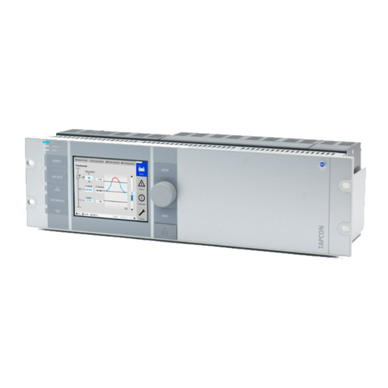
3 Product description Design The device is designed as a 19 inch slide-in housing with modular hardware equipment. The device's individual assemblies are described in the following section. Figure 2: Front view Maschinenfabrik Reinhausen GmbH 2016 3587317/10 EN TAPCON®... -
Page 20: Operating Controls
ENTER key Confirm selection and save modified parameters. Rotary knob Navigation through individual menu items and parameters. BACK key Exit the current menu. Go to the previ- ous menu level. TAPCON® 3587317/10 EN Maschinenfabrik Reinhausen GmbH 2016... -
Page 21: Display Elements
The device has a graphics display and 8 LEDs, which indicate the various operating statuses or events. Figure 4: Display elements Power supply LED AVR STATUS LED ALARM LED REMOTE LED AVR AUTO LED RAISE VOLTAGE LED AVR MANUAL LED LOWER VOLTAGE LED Display Maschinenfabrik Reinhausen GmbH 2016 3587317/10 EN TAPCON®... - Page 22 3 Product description Display The display for the TAPCON® is divided into the following areas: Figure 5: Display Display area Secondary navigation or navi- gation path Primary navigation Status bar TAPCON® 3587317/10 EN Maschinenfabrik Reinhausen GmbH 2016...
- Page 23 Figure 6: Measured value trend Desired value Upper limit of bandwidth Trend of measured voltage Delay time T1/T2 Trend of corrected voltage Lower limit of bandwidth (correction due to compensa- tion or parallel operation) Maschinenfabrik Reinhausen GmbH 2016 3587317/10 EN TAPCON®...
- Page 24 3 Product description Figure 7: Transformer overview with display showing current measured values Designation of transformer Tap position of the on-load tap-changer (next, current, previous) Voltage Control deviation in % (with correction) Current Power factor TAPCON® 3587317/10 EN Maschinenfabrik Reinhausen GmbH 2016...
-
Page 25: Front Interface
DC voltage power supply unit 20...70 V DC 3.5.4.2 Central processing unit The CPU I assembly is the central computing unit for the device. It contains the following interfaces: ▪ Internal system interface RS232 (COM1) ▪ Serial interface RS232/485 (COM2) Maschinenfabrik Reinhausen GmbH 2016 3587317/10 EN TAPCON®... - Page 26 2x CAN bus (CAN 1, CAN 2) Figure 9: CPU I assembly 3.5.4.3 Voltage measurement and current measurement The UI 1 assembly is used for measuring 1-phase voltage and current. Figure 10: UI 1 assembly TAPCON® 3587317/10 EN Maschinenfabrik Reinhausen GmbH 2016...
- Page 27 ▪ DIO 28-15: 28 inputs, 15 outputs (6 N/O contacts, 9 change-over con- tacts) ▪ DIO 42-20 (HL): 42 inputs, 20 outputs (8 N/O contacts, 12 change-over contacts) Figure 12: DIO 42-20 assembly Maschinenfabrik Reinhausen GmbH 2016 3587317/10 EN TAPCON®...
- Page 28 The following interfaces are available: ▪ 2x RJ45 (ETH12, ETH22) ▪ 2x Duplex-LC (SFP module) (ETH11, ETH21) The media converter is designed to be transparent for the network and does not have its own IP address. TAPCON® 3587317/10 EN Maschinenfabrik Reinhausen GmbH 2016...
- Page 29 2x RJ45 (ETH23, ETH24), device-internal connection – 2x Duplex-LC (SFP module) (ETH21, ETH22), redundancy connec- tion The following redundancy functions are available to you according to your order: ▪ PRP (standard setting) ▪ RSTP Maschinenfabrik Reinhausen GmbH 2016 3587317/10 EN TAPCON®...
-
Page 30: Operating Concept
If you want to operate the device via the operating controls and visualization at the same time, you have to log in on the device and via the visualization. TAPCON® 3587317/10 EN Maschinenfabrik Reinhausen GmbH 2016... - Page 31 In these operating instructions, the path for navigating to a parameter is al- ways shown in an abridged form: Go to Settings > Parameter > Control > Desired value 1. Setting the parameters Depending on the parameter, you can undertake the settings in various ways. Maschinenfabrik Reinhausen GmbH 2016 3587317/10 EN TAPCON®...
- Page 32 ð If operating via the front panel, the numerical keypad appears. Figure 17: Entering value Enter the value you want and confirm with Press the Accept button to save the modified parameter. TAPCON® 3587317/10 EN Maschinenfabrik Reinhausen GmbH 2016...
- Page 33 Use rotary knob to select the text box and press the key. ð If operating via the front panel, the keyboard appears. Figure 18: Entering text Enter the text you want and confirm with Press the Accept button to save the modified parameter. Maschinenfabrik Reinhausen GmbH 2016 3587317/10 EN TAPCON®...
-
Page 34: Packaging, Transport And Storage
▪ Completeness based on the delivery slip ▪ External damage of any type. The checks must take place after unloading when the crate or transport con- tainer can be accessed from all sides. TAPCON® 3587317/10 EN Maschinenfabrik Reinhausen GmbH 2016... -
Page 35: Storage Of Shipments
Ensure sufficient carrying capacity of the ground. ▪ Keep entrance paths free. ▪ Check stored goods at regular intervals. Also take appropriate action af- ter storms, heavy rain or snow and so on. Maschinenfabrik Reinhausen GmbH 2016 3587317/10 EN TAPCON®... -
Page 36: Mounting
To the floor of the control cabinet 88.9 mm (3.5 in) To the roof of the control cabinet Corresponds to 2 RU Between two 19" devices Table 7: Minimum distances in the control cabinet TAPCON® 3587317/10 EN Maschinenfabrik Reinhausen GmbH 2016... - Page 37 Figure 20: Example of device mounting in a 19" frame Mounting in a control panel with a 19" flush control panel frame To mount the device in a control panel, proceed as follows: ü Scope of delivery is complete. Maschinenfabrik Reinhausen GmbH 2016 3587317/10 EN TAPCON®...
- Page 38 5 Mounting Figure 21: Scope of delivery Produce cut-out in control panel. Figure 22: Producing cut-out in control panel Mounting cage nuts Figure 23: Mounting cage nuts TAPCON® 3587317/10 EN Maschinenfabrik Reinhausen GmbH 2016...
- Page 39 Secure frame to control panel. Figure 24: Securing frame to control panel Slide device into flush control panel frame and secure. Figure 25: Securing device Close cover of flush control panel frame. Figure 26: Closing cover Maschinenfabrik Reinhausen GmbH 2016 3587317/10 EN TAPCON®...
-
Page 40: Connecting Device
400 m (<25 Ω/km) DIO 42-20 Signal outputs* DIO 28-15, Shielded 1.5 mm DIO 42-20 Signal inputs AIO 2, AIO Shielded 1 mm 400 m (<25 Ω/km) Signal outputs AIO 2, AIO Shielded 1 mm TAPCON® 3587317/10 EN Maschinenfabrik Reinhausen GmbH 2016... -
Page 41: Information About Connecting Serial Interfaces Rs232 And Rs485
► Only use data cables which comply with the description below. RS232 (D-SUB 9-pole) For connecting the device via the RS232 interface (COM2), use a data cable with the following structure: Figure 27: RS232 data cable (9-pole) Maschinenfabrik Reinhausen GmbH 2016 3587317/10 EN TAPCON®... - Page 42 5 Mounting RS485 (D-SUB 9-pole) To connect the device via the RS485 interface (COM2), use a data cable with the following structure: Figure 28: RS485 data cable TAPCON® 3587317/10 EN Maschinenfabrik Reinhausen GmbH 2016...
- Page 43 Cable shielding is connected with the plug using one of the two following variants: – Shielding is screwed to the traction relief device. – Shielding is soldered to the plug housing. Figure 30: Example of a soldered shielding on a plug housing Maschinenfabrik Reinhausen GmbH 2016 3587317/10 EN TAPCON®...
-
Page 44: Information About Laying Fiber-Optic Cable
(for example signal lines) in the same cable duct. ▪ Maintain a space of more than 100 mm between lines which cause in- terference and those which are susceptible to interference. TAPCON® 3587317/10 EN Maschinenfabrik Reinhausen GmbH 2016... - Page 45 ▪ Connect full surface of shielding (360º) to device or to a nearby ground- ing bar. Using "pigtails" may limit the effectiveness of the shielding. Connect close- fitting shielding to cover all areas. Maschinenfabrik Reinhausen GmbH 2016 3587317/10 EN TAPCON®...
- Page 46 Signal lines and power lines/switching lines must be laid in separate ca- ble ducts. ▪ The device must be grounded at the screw provided, the protective grounding connection, using a ground strap (cross-section min. 8 mm²). TAPCON® 3587317/10 EN Maschinenfabrik Reinhausen GmbH 2016...
- Page 47 Connect all devices to a potential compensation rail to compensate for the potential. Connect CAN bus cable's shielding to all connected devices. Variant 2: The connected devices have different potential Note that the shielding is less effective with this variant. Maschinenfabrik Reinhausen GmbH 2016 3587317/10 EN TAPCON®...
- Page 48 ► If both devices have different potentials, only connect the cable's shielding to one device. Variant 1: TAPCON® and receiver (e.g. 20 mA transmitter, resistor contact series) are on the same potential If the devices to be connected share the same potential, proceed as follows: ►...
- Page 49 ▪ Connect shielding to one of the shielding clips on side plate of TAPCON® Figure 35: Placement of shielding on the shielding clip on side plate of TAPCON® ▪ Connect shielding to a grounding bar of control cabinet Figure 36: Examples of supporting shielding on ground bar (on left: Direct connection...
-
Page 50: Mounting Terminating Resistor Of Can Bus
Note the connection diagram. ü Use only the specified cables for wiring. Note the cable recommenda- tion. ü Wire the lines to the system periphery [► 50]. Strip insulation from lines and leads. TAPCON® 3587317/10 EN Maschinenfabrik Reinhausen GmbH 2016... -
Page 51: Checking Functional Reliability
An incorrectly connected device can lead to damages in the device and sys- tem periphery. ► Check the entire configuration before commissioning. ► Prior to commissioning, be sure to check the actual voltage and operat- ing voltage. Maschinenfabrik Reinhausen GmbH 2016 3587317/10 EN TAPCON®... - Page 52 Check the following: ▪ Once you have connected the device to the grid, the display shows the MR logo and then the operating screen. ▪ The voltage display LED on the top left of the device's front panel lights The device is fully mounted and can be configured. The actions required for this are described in the following chapter.
-
Page 53: Commissioning
Commissioning wizard If you want the device to help when setting the relevant parameters, you can use the commissioning wizard TILA (TAPCON® Interactive Launch Assist). The commissioning wizard provides a choice of parameters you can config- ure in order. -
Page 54: Setting Parameters
[► 57]. Setting parameters To commission the TAPCON®, you must set the following parameters. For more detailed information about the parameters, refer to the respective sec- tions. To set the parameters, you need the necessary access rights [►... -
Page 55: Setting Date And Time
If you would like to set the date and time manually, you have to enter the val- ues in the following formats: Date Time DD.MM.YYYY HH:MM Table 9: Formats The time does not switch from daylight saving time to standard time and back automatically. Maschinenfabrik Reinhausen GmbH 2016 3587317/10 EN TAPCON®... -
Page 56: Setting Further Parameters
Set the current-transformer circuit, voltage-transformer circuit, and phase angle correction [► 91]. Setting control parameters Set the following control parameters: Set the desired value [► 69]. Set the bandwidth [► 83]. Set delay time T1 [► 84]. TAPCON® 3587317/10 EN Maschinenfabrik Reinhausen GmbH 2016... -
Page 57: Function Tests
You must ensure that REMOTE mode is disabled before you can control the on-load tap-changer manually in manual mode. ▪ You can only activate the on-load tap-changer manually in manual mode using the keys. Maschinenfabrik Reinhausen GmbH 2016 3587317/10 EN TAPCON®... -
Page 58: Testing A Control Function
1 step. 14. Press to select auto mode. ð If the actual voltage is outside the bandwidth, the device returns the on-load tap-changer to the original operating position after 20 sec- onds. TAPCON® 3587317/10 EN Maschinenfabrik Reinhausen GmbH 2016... -
Page 59: Checking Parallel Operation
To obtain perfect functioning in parallel operation, the TAPCON® must be commissioned in simplex mode. Make sure that the conditions below have been fulfilled. ▪ All TAPCON® units are set to the same operating parameters for "de- sired value" and "delay time T1" [► ▪... - Page 60 The status display in the Parallel operation menu lights up blue. ð The two TAPCON® must be within the bandwidth. Set the desired value of both TAPCON® to the voltage currently meas- ured. On one of the two transformers, raise the tap position of the on-load tap- changer by one setting;...
- Page 61 Set the value determined for the "circulating reactive current blocking limit" for the TAPCON® units in parallel operation as well. If one TAPCON® or all of the TAPCON® units indicate Circulating reactive current blocking limit exceeded even though the control inputs are correctly connected for all TAPCON®...
- Page 62 Compare the tap position displays of master and follower . All of the TAPCON® units must display the same tap position. If this is not the case, switch all TAPCON® units to the same tap position. Figure 43: Comparing the tap position Master...
- Page 63 12. Press on the master and follower to manually set the desired step. ð The function tests for the tap synchronization method are complete. Installation and commissioning of the device is complete. Maschinenfabrik Reinhausen GmbH 2016 3587317/10 EN TAPCON®...
-
Page 64: Functions And Settings
Activate/deactivate launching the commissioning wizard after the device is restarted ▪ Measured value display ▪ Transformer name ▪ Remote behavior Settings for web-based visualization ▪ IP address ▪ Subnet mask ▪ Gateway address ▪ SSL encryption Figure 44: General TAPCON® 3587317/10 EN Maschinenfabrik Reinhausen GmbH 2016... -
Page 65: Activating/Deactivating Automatic Launch Of Commissioning Wizard
Select the option you want. Press the Accept button to save the modified parameter. 7.1.3 Remote behavior You can use this parameter to set the behavior of the TAPCON® in Remote operating mode. You can select the following options: Option Description Inputs The TAPCON®... - Page 66 You can use this parameter to set whether access to the visualization should take place via an SSL-encrypted connection. To activate SSL encryption, proceed as follows: Go to Settings > Parameters > General > SSL encryption. TAPCON® 3587317/10 EN Maschinenfabrik Reinhausen GmbH 2016...
- Page 67 Activate automatic assignment of the IP address via DHCP on the PC. Enter the visualization's IP address http://192.168.165.1, or if SSL encryption is active enter https://192.168.165.1, on the PC in the browser. The visualization is accessed. ð Maschinenfabrik Reinhausen GmbH 2016 3587317/10 EN TAPCON®...
- Page 68 Figure 46: Establishing connection via the ETH2.2 interface on the back Go to Communication on the device to display the device's IP address. Figure 47: Displaying Communication Assign the PC an unique IP address in the same subnet as the device (e.g. 192.0.1.100). TAPCON® 3587317/10 EN Maschinenfabrik Reinhausen GmbH 2016...
-
Page 69: Control
Accessing online help The web-based visualization has an online help section. To call up the online help, proceed as follows: Call up web-based visualization with the PC. Select the MR logo in the status line. ð The online help appears. Control All of the parameters required for the regulation function are described in this section. - Page 70 Setting the desired value To set the desired value, proceed as follows: Go to Settings > Parameter > Control > Desired value. Enter desired value. Press the Accept button to save the modified parameter. TAPCON® 3587317/10 EN Maschinenfabrik Reinhausen GmbH 2016...
- Page 71 Setting desired value 1 To set the desired value, proceed as follows: Go to Settings > Parameter > Control > Desired value. Enter desired value. Press the Accept button to save the modified parameter. Maschinenfabrik Reinhausen GmbH 2016 3587317/10 EN TAPCON®...
- Page 72 To set the desired value sep width, proceed as follows: Go to Settings > Parameters > Control > Desired value step width. Enter desired value step width. Press the Accept button to save the modified parameter. TAPCON® 3587317/10 EN Maschinenfabrik Reinhausen GmbH 2016...
- Page 73 7.2.1.6 Active power-dependent adjustment of desired voltage value The TAPCON® Dynamic Setpoint Control (TDSC) function is used to adapt the desired voltage value depending on the measured active power. This al- lows you to compensate for a voltage drop during increased load or an in- crease in voltage due to a decentralized feed-in.
- Page 74 Figure 50: Active power-dependent adjustment of desired voltage value Desired value Minimum desired value Measured active power Maximum desired value meas Active power at minimum Set desired value when desired value measured active power = Active power at maximum desired value TAPCON® 3587317/10 EN Maschinenfabrik Reinhausen GmbH 2016...
- Page 75 If the measured active power 0 ≤ P ≤ P , the desired value is calculated meas using the following formula: To activate the active power-dependent adjustment of the desired voltage value, you need to set the following parameters: Maschinenfabrik Reinhausen GmbH 2016 3587317/10 EN TAPCON®...
- Page 76 Go to Settings > Parameters > Control > TDSC Pmax/Pmin. Enter active power for maximum/minimum desired value. Press the Accept button to save the modified parameter. TAPCON® 3587317/10 EN Maschinenfabrik Reinhausen GmbH 2016...
- Page 77 Active power-dependent adjustment of desired voltage value with 3 different desired values The TAPCON® Dynamic Setpoint Control (TDSC) function is used to adapt the desired voltage value depending on the measured active power. This al- lows you to compensate for a voltage drop during increased load or an in- crease in voltage due to a decentralized feed-in.
- Page 78 Figure 51: Active power-dependent adjustment of desired voltage value Desired value Minimum desired value Measured active power Maximum desired value meas Active power at minimum Set desired value when desired value measured active power = Active power at maximum desired value TAPCON® 3587317/10 EN Maschinenfabrik Reinhausen GmbH 2016...
- Page 79 If the measured active power 0 ≤ P ≤ P , the desired value is calculated meas using the following formula: To activate the active power-dependent adjustment of the desired voltage value, you need to set the following parameters: Maschinenfabrik Reinhausen GmbH 2016 3587317/10 EN TAPCON®...
- Page 80 Go to Settings > Parameters > Control > TDSC Pmax/Pmin. Enter active power for maximum/minimum desired value. Press the Accept button to save the modified parameter. TAPCON® 3587317/10 EN Maschinenfabrik Reinhausen GmbH 2016...
- Page 81 61 V 62 V 63 V 64 V 65 V 66 V 67 V 68 V 69 V 70 V 71 V 72 V 73 V 74 V 75 V 76 V 77 V Maschinenfabrik Reinhausen GmbH 2016 3587317/10 EN TAPCON®...
- Page 82 99 V 100 V 101 V 102 V 103 V 104 V 105 V 106 V 107 V 108 V 109 V 110 V 111 V 112 V 113 V 114 V 115 V TAPCON® 3587317/10 EN Maschinenfabrik Reinhausen GmbH 2016...
-
Page 83: Bandwidth
You can use this parameter to set the maximum permissible deviation in measured voltage U from the desired value U . The following section actual desired describes how you determine and set the bandwidth. Maschinenfabrik Reinhausen GmbH 2016 3587317/10 EN TAPCON®... -
Page 84: Delay Time T1
Press the Accept button to save the modified parameter. 7.2.3 Delay time T1 Delay time T1 delays the issuing of a tap-change command for a defined pe- riod. This prevents unnecessary tap-change operations if the tolerance bandwidth is exited briefly. TAPCON® 3587317/10 EN Maschinenfabrik Reinhausen GmbH 2016... - Page 85 To set the delay time T1, proceed as follows: Go to Settings > Parameters > Control > Delay time T1. Enter delay time T1. Press the Accept button to save the modified parameter. Maschinenfabrik Reinhausen GmbH 2016 3587317/10 EN TAPCON®...
-
Page 86: Delay Time T2
Press the Accept button to save the modified parameter. 7.2.4 Delay time T2 You can use this parameter to set the delay time T2. Delay time T2 is used to compensate for large control deviations faster. TAPCON® 3587317/10 EN Maschinenfabrik Reinhausen GmbH 2016... - Page 87 , a control impulse is output to the motor-drive unit after the set de- lay time T1 . If the measured voltage U is still outside the bandwidth, actual Maschinenfabrik Reinhausen GmbH 2016 3587317/10 EN TAPCON®...
- Page 88 To activate delay time T2, proceed as follows: Go to Settings > Parameter > Control > Activate delay T2. Select the option you want. Press the Accept button to save the modified parameter. TAPCON® 3587317/10 EN Maschinenfabrik Reinhausen GmbH 2016...
-
Page 89: Setting Regulation Mode
▪ L3/N or L3/L1 To set the control variable, proceed as follows: Go to Settings > Parameters > Measurement. Select the option you want. Press the Accept button to save the modified parameter. Maschinenfabrik Reinhausen GmbH 2016 3587317/10 EN TAPCON®... -
Page 90: Transformer Data
Go to Settings > Parameters > Transformer data > Secondary trans- former voltage. Enter secondary transformer voltage. Press the Accept button to save the modified parameter. 7.3.3 Setting primary transformer current This parameter can be used to set the primary transformer current. TAPCON® 3587317/10 EN Maschinenfabrik Reinhausen GmbH 2016... -
Page 91: Setting The Secondary Transformer Current
Measurement mode Table 15: Setting configuration of current transformer and voltage transformer (UI 3 measuring module) *) According to setting of UI measuring channels parameter. Note the following examples of common transformer circuits: Maschinenfabrik Reinhausen GmbH 2016 3587317/10 EN TAPCON®... - Page 92 The voltage U and current I are in phase. ▪ The voltage drop on a phase conductor is determined by the current I If you use this circuit, set the device as follows: TAPCON® 3587317/10 EN Maschinenfabrik Reinhausen GmbH 2016...
- Page 93 ) / √3. If you use this circuit, set the device as follows: Parameter Option Voltage-transformer circuit 3 Ph differential voltage Current-transformer circuit 3 Ph total current Phase angle correction 0° Table 18: Circuit C Maschinenfabrik Reinhausen GmbH 2016 3587317/10 EN TAPCON®...
- Page 94 The current I is ahead of voltage U by 30°. ▪ The voltage drop on a phase conductor is determined by the current I If you use this circuit, set the device as follows: TAPCON® 3587317/10 EN Maschinenfabrik Reinhausen GmbH 2016...
- Page 95 If you use this circuit, set the device as follows: Parameter Option Voltage-transformer circuit 3 Ph differential voltage Current-transformer circuit 3 Ph phase current Phase angle correction -30° Table 21: Circuit F Circuit G ▪ Three-phase measurement. Maschinenfabrik Reinhausen GmbH 2016 3587317/10 EN TAPCON®...
- Page 96 3-phase measurement (channels 1, 2, 3) Measurement mode Phase-neutral Table 23: Circuit H Setting voltage-transformer circuit You can use this parameter to set your voltage transformer's circuit. You can select the following options: TAPCON® 3587317/10 EN Maschinenfabrik Reinhausen GmbH 2016...
- Page 97 To do so, proceed as follows: Go to Settings > Parameters > Transformer data > Phase angle cor- rection. Select the option you want. Press the Accept button to save the modified parameter. Maschinenfabrik Reinhausen GmbH 2016 3587317/10 EN TAPCON®...
-
Page 98: Control Of The Motor-Drive Unit
Setting the switching pulse for controlling the motor-drive unit You can use the switching pulse type, switching pulse time and switching pulse pause parameters to adapt the switching pulse of the TAPCON® to the requirements of the motor-drive unit's control. - Page 99 If the TAPCON® is operated as a follower in parallel operation in this case, then the TAPCON® issues the switching pulse until one of the following re- quirements has been met: ▪...
-
Page 100: Setting Motor Runtime Monitoring
You can use the switching pulse time parameter to set the maximum dura- tion of the switching pulse. It resets after the switching pulse time has elapsed or if the TAPCON® receives the Motor running signal beforehand or the tap position is changed. -
Page 101: Setting The Switching Direction
Setting switching direction monitoring You can use this parameter to set the switching direction monitoring. This function monitors whether a tap-change operation in the wrong direction has been undertaken (e.g. due to a wiring mistake). Maschinenfabrik Reinhausen GmbH 2016 3587317/10 EN TAPCON®... -
Page 102: Line Drop Compensation
The device pro- vides 2 methods of compensation for this purpose: ▪ R&X compensation ▪ Z compensation Figure 59: Setting line drop compensation Note the description below for configuration of line drop compensation. TAPCON® 3587317/10 EN Maschinenfabrik Reinhausen GmbH 2016... -
Page 103: R&X Compensation
R&X compensation can compensate for voltage losses on the lines and therefore ensure correct voltage on the consumer. This requires precise line data. After you have entered all of the line data, the TAPCON® automatically calculates the ohmic and inductive voltage drop and takes this into account for automatic voltage regulation. -
Page 104: Z Compensation
To keep the voltage constant for the consumer, you can use Z compensation to activate a current-dependent increase in voltage. You can also define a limit value to avoid excess voltage on the transformer. Figure 62: Z compensation TAPCON® 3587317/10 EN Maschinenfabrik Reinhausen GmbH 2016... - Page 105 To set the voltage limit value, proceed as follows: Go to Settings > Parameter > Compensation > Voltage limit value. Enter voltage limit value. Press the Accept button to save the modified parameter. Maschinenfabrik Reinhausen GmbH 2016 3587317/10 EN TAPCON®...
-
Page 106: Tap Position Capture
For the analog tap position capture, you must set which tap positions corre- spond to the minimum analog signal and maximum analog signal. The device is configured at the factory according to the order. However, should modifications be necessary, note the following sections. TAPCON® 3587317/10 EN Maschinenfabrik Reinhausen GmbH 2016... - Page 107 Calibrate tap position capture over resistor contact series (optional) Carry out the calibration at an ambient temperature that corresponds to nor- mal operating conditions. This allows you to reduce measurement errors due to temperature fluctuations. Maschinenfabrik Reinhausen GmbH 2016 3587317/10 EN TAPCON®...
-
Page 108: Parallel Operation
For parallel operation with CAN communication: Current transformers with the same rated values must be used for all devices operating in parallel 7.7.1 Parallel operation methods You can undertake parallel operation with various parallel operation meth- ods. TAPCON® 3587317/10 EN Maschinenfabrik Reinhausen GmbH 2016... - Page 109 For the tap synchronization parallel operation method, you have to set the following parameters: Parameter Auto Master Follower Activate parallel oper- ation Parallel operation Auto. Tap Master Follower method synchroniza- tion CAN bus address Maschinenfabrik Reinhausen GmbH 2016 3587317/10 EN TAPCON®...
- Page 110 You can use the circulating reactive cur- rent sensitivity parameter to decrease or increase this extra control devia- tion. TAPCON® 3587317/10 EN Maschinenfabrik Reinhausen GmbH 2016...
- Page 111 You have to use current transformers with the same rated values for all transformers in parallel operation. ▪ If you wish to operate in parallel operation with existing devices, you have to activate the Retrofit TAPCON® 2xx [► 117] parameter. For the circulating reactive current minimization parallel operation method with CAN communication, you have to set the following parameters: ▪...
-
Page 112: Configuring Parallel Operation
Figure 67: Setting parallel operation The following sections describe how you can set the parameters. 7.7.2.1 Activating parallel operation You can use this parameter to activate or deactivate parallel operation. TAPCON® 3587317/10 EN Maschinenfabrik Reinhausen GmbH 2016... - Page 113 Setting parallel operation method You can use this parameter to set the parallel operation method. You can select the following options: Option Description Master The TAPCON® is des- Tap synchronization ignated as the master. [► 109] parallel opera- tion method Follower The TAPCON®...
- Page 114 0, the device is not able to calculate the voltage correction. To set the desired power factor, proceed as follows: Go to Settings > Parameters > Parallel operation > Desired power factor. TAPCON® 3587317/10 EN Maschinenfabrik Reinhausen GmbH 2016...
- Page 115 You can use this parameter to activate the circulating reactive current block- ing limit for the tap synchronization parallel operation method. The TAPCON® thereby calculates and monitors the circulating reactive current in the same manner as for the circulating reactive current minimization parallel operation method and provides you with the circulating reactive current blocking safety function.
- Page 116 To set the parameters, proceed as follows: Go to Settings > Parameters > Parallel operation > Error if no com- munication present. Select the option you want. TAPCON® 3587317/10 EN Maschinenfabrik Reinhausen GmbH 2016...
-
Page 117: Tapcon® 2Xx Retrofit
Press the Accept button to save the modified parameter. 7.7.3 TAPCON® 2xx retrofit The TAPCON® 2xx retrofit function allows you to operate the device in par- allel operation with existing devices. Parallel operation with the following ex- isting devices is supported: ▪... -
Page 118: Detecting Parallel Operation Via Group Inputs (Optional)
TRAFOGUARD® with "Voltage regulation" options package If you wish to operate several devices in parallel operation with existing devi- ces, you have to activate the TAPCON® 2xx retrofit function on each device. Figure 69: Parallel operation of 2 devices with one TAPCON® 2xx. The TAPCON®... -
Page 119: Detecting Parallel Operation Via Topology (Optional)
Figure 70: Example of a circuit breaker configuration A TAPCON® records the status of the circuit breakers via digital inputs and reports this to the connected TAPCON® by CAN bus. On the basis of the CAN bus message, the TAPCON® decide whether parallel operation is ac- tive or not. - Page 120 7 Functions and settings The TAPCON® are split into two groups for data transmission by CAN bus: ▪ Topology master: TAPCON®, which records the status of the circuit breakers via digital inputs and reports this by CAN bus. ▪ Topology client: TAPCON®, which receives the status of the circuit breakers by CAN bus.
- Page 121 Circuit breaker configuration You can set the assignment of circuit breakers to the individual node points. The TAPCON® uses the assignment to detect which transformers are con- nected in parallel with one another. Upon delivery, the device is configured in accordance with your order. Note the connection diagram provided for the configuration.
-
Page 122: Limit Values
S<< S< S> S>> Active power P<< P< P> P>> Reactive power Q<< Q< Q> Q>> Power factor cos phi<< cos phi< Bandwidth B%< B%> Tap position Position< Position> Table 30: Limit values TAPCON® 3587317/10 EN Maschinenfabrik Reinhausen GmbH 2016... - Page 123 "Relative limit value". Absolute limit value You can use this parameter to set the limit value as a fixed absolute value. Unlike the relative value, this limit is not dependent on a reference value. Maschinenfabrik Reinhausen GmbH 2016 3587317/10 EN TAPCON®...
- Page 124 Auto-manual The device blocks automatic voltage regulation and blocking for manual tap-change operations to a higher tap position. raise step Switch to Man- The devices switches to manual mode. TAPCON® 3587317/10 EN Maschinenfabrik Reinhausen GmbH 2016...
-
Page 125: Voltage Monitoring
Also refer to 2 Limit values [► 122] 7.8.2 Current monitoring For monitoring of the transformer's current load current, you can set 4 limit values: ▪ I<< ▪ I< ▪ I> ▪ I>> Maschinenfabrik Reinhausen GmbH 2016 3587317/10 EN TAPCON®... -
Page 126: Power Monitoring
If the limit value is exceeded, the device issues a message . To set the power monitoring, proceed as follows: Go to Settings > Parameters > Power monitoring. Select the parameter you want. Set parameter. Press the Accept button to save the modified parameter. TAPCON® 3587317/10 EN Maschinenfabrik Reinhausen GmbH 2016... -
Page 127: Bandwidth Monitoring
The event is automatically acknowledged as soon as the measured value returns to within the set bandwidth. The following parameters are available for setting function monitoring: ▪ Function monitoring ▪ Hysteresis ▪ Delay time Figure 75: Setting function monitoring Maschinenfabrik Reinhausen GmbH 2016 3587317/10 EN TAPCON®... -
Page 128: Switching Interval Monitoring
You can have the following operations monitored: ▪ Total operations: Total raise operations and lower operations ▪ Lower operations: Total lower operations ▪ Raise operations: Total raise operations TAPCON® 3587317/10 EN Maschinenfabrik Reinhausen GmbH 2016... - Page 129 Off: The internal counter is not reset by intermediate raise or lower tap- change operations. Behavior You can use this parameter to set the behavior of the TAPCON® if the maxi- mum permissible number of tap-change operations is exceeded: Setting Behavior Switching interval monitoring is disabled.
-
Page 130: Tap Position Monitoring
Press the Accept button to save the modified parameter. Power flow monitoring A reversal of power flow occurs if the active power is negative. You can set the following parameters for this: ▪ Behavior ▪ Hysteresis ▪ Delay time TAPCON® 3587317/10 EN Maschinenfabrik Reinhausen GmbH 2016... - Page 131 You can select the following options: Setting Behavior ▪ The negative power flow is ignored. ▪ The TAPCON® continues regulating. Event only ▪ The Reversal of power flow event is issued. ▪ If Z compensation is activated, this function is deactivated.
- Page 132 The Reversal of power flow event is issued. step ▪ If Z compensation is activated, this function is deactivated. ▪ The TAPCON® causes a tap-change opera- tion to the tap position you defined in the"Target tap position" [► 133] parameter. ▪...
-
Page 133: Target-Tap-Position Operation
7.10 Target-tap-position operation You can use this parameter to define a target tap position. When target-tap- position operation is activated, the TAPCON® automatically switches to this target tap position. Figure 77: Setting target-tap-position operation To set the target tap position, proceed as follows: Go to Settings >... -
Page 134: Configuring Analog Inputs And Outputs (Optional)
You can set the following parameters: ▪ Function: Select function of analog sensor. You cannot change grayed out entries. ▪ Slot/channel: Select slot and channel of analog sensor. Note the con- nection diagram supplied. TAPCON® 3587317/10 EN Maschinenfabrik Reinhausen GmbH 2016... - Page 135 ▪ The busbar slot numbers increase from the left when viewed from be- hind. Note that the CPU assembly always occupies 2 slots. Maschinenfabrik Reinhausen GmbH 2016 3587317/10 EN TAPCON®...
-
Page 136: Displaying Temperature Curve (Optional)
If using additional temperature sensors (generic temperature 1...8), you can display the temperature curve for these temperatures over the last 10 days. To do so, proceed as follows: ► Go to Information > Gener. temperatures. Figure 81: Generic temperatures TAPCON® 3587317/10 EN Maschinenfabrik Reinhausen GmbH 2016... -
Page 137: Scada
You can use this parameter to set the subnet mask. Be sure to enter a valid network mask that is not 0.0.0.0, otherwise it will not be possible to connect to the device. Maschinenfabrik Reinhausen GmbH 2016 3587317/10 EN TAPCON®... - Page 138 Enter device name. Press the Accept button to save the modified parameter. Edition You can use this parameter to switch between edition 1 and edition 2 of the control system protocol IEC 61850. TAPCON® 3587317/10 EN Maschinenfabrik Reinhausen GmbH 2016...
-
Page 139: Displaying Iec 61850 Log (Optional)
Figure 83: Displaying IEC 61850 log To call up the IEC 61850 log, proceed as follows: Go to Information > IEC 61850 log. Optional: Press the Server or Client button to change the display. Maschinenfabrik Reinhausen GmbH 2016 3587317/10 EN TAPCON®... -
Page 140: Configuring Iec 60870-5-101 (Optional)
115200 baud To set the baud rate, proceed as follows: Go to Settings > Parameters > IEC 60870-5-101 > Baud rate. Select baud rate. Press the Accept button to save the modified parameter. TAPCON® 3587317/10 EN Maschinenfabrik Reinhausen GmbH 2016... - Page 141 Go to Settings > Parameters > IEC 60870-5-101 > Octet number of ASDU address. Set octet number of ASDU address. Press the Accept button to save the modified parameter. ASDU address You can use this parameter to set the address of the ASDU. Maschinenfabrik Reinhausen GmbH 2016 3587317/10 EN TAPCON®...
- Page 142 You can use this parameter to set the parity. You can select the following options: ▪ None ▪ Even ▪ To set the parity, proceed as follows: Go to Settings > Parameters > IEC 60870-5-101 > Parity. TAPCON® 3587317/10 EN Maschinenfabrik Reinhausen GmbH 2016...
-
Page 143: Configuring Iec 60870-5-103 (Optional)
▪ RS485 To select the serial interface, proceed as follows: Go to Settings > Parameters > IEC 60870-5-103 > Serial interface. Select serial interface. Press the Accept button to save the modified parameter. Maschinenfabrik Reinhausen GmbH 2016 3587317/10 EN TAPCON®... - Page 144 ▪ None ▪ Even ▪ To set the parity, proceed as follows: Go to Settings > Parameters > IEC 60870-5-103 > Parity. Select parity. Press the Accept button to save the modified parameter. TAPCON® 3587317/10 EN Maschinenfabrik Reinhausen GmbH 2016...
-
Page 145: Configuring Iec 60870-5-104 (Optional)
Go to Settings > Parameters > IEC 60870-5-104 > IP address. Enter IP address. Press the Accept button to save the modified parameter. Subnet mask You can use this parameter to set the subnet mask. Maschinenfabrik Reinhausen GmbH 2016 3587317/10 EN TAPCON®... - Page 146 You can use this parameter to set the address of the ASDU. To set the ASDU address, proceed as follows: Go to Settings > Parameters > IEC 60870-5-104 > ASDU address. Set ASDU address. Press the Accept button to save the modified parameter. TAPCON® 3587317/10 EN Maschinenfabrik Reinhausen GmbH 2016...
-
Page 147: Configuring Modbus (Optional)
TCP port (only with Modbus-TCP) You can use this parameter to set the TCP port. To set the TCP port, proceed as follows: Go to Settings > Parameters > Modbus > TCP port. Maschinenfabrik Reinhausen GmbH 2016 3587317/10 EN TAPCON®... - Page 148 RS232 ▪ RS485 To select the serial interface, proceed as follows: Go to Settings > Parameters > Modbus > Serial interface. Select serial interface. Press the Accept button to save the modified parameter. TAPCON® 3587317/10 EN Maschinenfabrik Reinhausen GmbH 2016...
- Page 149 To set the number of stop bits, proceed as follows: Go to Settings > Parameters > Modbus > Number of stop bits. Set number of stop bits. Press the Accept button to save the modified parameter. Maschinenfabrik Reinhausen GmbH 2016 3587317/10 EN TAPCON®...
-
Page 150: Configuring Dnp3 (Optional)
Go to Settings > Parameters > DNP3 > IP address. Enter IP address. Press the Accept button to save the modified parameter Subnet mask (only with TCP transmission type) You can use this parameter to set the subnet mask. TAPCON® 3587317/10 EN Maschinenfabrik Reinhausen GmbH 2016... - Page 151 RS232 ▪ RS485 To select the serial interface, proceed as follows: Go to Settings > Parameters > DNP3 > Serial interface. Select serial interface. Press the Accept button to save the modified parameter. Maschinenfabrik Reinhausen GmbH 2016 3587317/10 EN TAPCON®...
- Page 152 Press the Accept button to save the modified parameter. Repetition of unsolicited messages You can use this parameter to set how often the device is to send an unsoli- cited message until it receives a response from the DNP3 master. TAPCON® 3587317/10 EN Maschinenfabrik Reinhausen GmbH 2016...
- Page 153 To set the user ID code, proceed as follows: Go to Settings > Parameters > DNP3 > User ID code. Enter the user ID code. Press the Accept button to save the modified parameter. Maschinenfabrik Reinhausen GmbH 2016 3587317/10 EN TAPCON®...
-
Page 154: Configuring Goose (Optional)
LLN0. ▪ GSE elements for the configuration of the GOOSE message can be cre- ated under ConnectedAP. ▪ The maximum number of data points per GOOSE message is defined in Private Element type="MR-MAX-GOOSE-PUBLISH-FCDA". TAPCON® 3587317/10 EN Maschinenfabrik Reinhausen GmbH 2016... - Page 155 ▪ The maximum number of usable GSEControl elements is defined in TEMPLATE.icd under Services GOOSE. ▪ The shortest repeat time is defined in Private Element type="MR-MIN- TIME-GOOSE". Example: Configuration To configure the device as a GOOSE publisher, you have to call up the vis- ualization via a PC.
- Page 156 After the successful import, restart the device. ð The system restarts and checks the configuration. If the configuration failed, an error message appears and the device resets the configura- tion to the one with which it was delivered. TAPCON® 3587317/10 EN Maschinenfabrik Reinhausen GmbH 2016...
- Page 157 DataSet and GSE block. The referenced DataSet may contain data ob- jects (DO) or data attributes (DA). The maximum number of usable data points per GOOSE message is defined in Private Element type="MR-MAX- GOOSE-SUBSCRIBER-FCDA". You can only use data points with bType BOOLEAN (true | false) and Dbpos (intermediate-state | off | on | bad-state).
- Page 158 Press the Accept button to save the configuration. ð The Restart device dialog appears. Select Cancel if you want to configure other data points or OK to com- plete the modified configuration by restarting the device. TAPCON® 3587317/10 EN Maschinenfabrik Reinhausen GmbH 2016...
-
Page 159: Time Synchronization
You can use this parameter to activate time synchronization using an SNTP time server. To activate time synchronization using SNTP, proceed as follows: Go to Settings > Parameters > Time synchronization > Time syn- chronization via SNTP. Select the option you want. Maschinenfabrik Reinhausen GmbH 2016 3587317/10 EN TAPCON®... -
Page 160: Entering The Time Server Address
To enter the time server address of the second SNTP server, proceed as fol- lows: Go to Settings > Parameters > Time synchronization > SNTP time server 2. Enter time server address. Press the Accept button to save the modified parameter. TAPCON® 3587317/10 EN Maschinenfabrik Reinhausen GmbH 2016... -
Page 161: Setting The Time Zone
To set the reference time, proceed as follows: Go to Settings > Parameters > Time synchronization > Reference time. Select the option you want. Press the Accept button to save the modified parameter. Maschinenfabrik Reinhausen GmbH 2016 3587317/10 EN TAPCON®... -
Page 162: User Administration
▪ Display, modify, and acknowledge all events Administrator User who can view and modify all data. ▪ Read all parameters ▪ Display, modify, and acknowledge all events Table 38: Roles in delivery status TAPCON® 3587317/10 EN Maschinenfabrik Reinhausen GmbH 2016... -
Page 163: Changing Password
Note that the password must satisfy the following requirements: ▪ At least 8 characters ▪ At least 3 of the 4 following character types – Upper case letters – Lower case letters – Numbers – Special characters Maschinenfabrik Reinhausen GmbH 2016 3587317/10 EN TAPCON®... -
Page 164: Creating, Editing And Deleting Users
The user data is still stored in the device. ▪ Auto login: You can activate the Auto-login function for a user. This user is automatically logged in when the system is restarted or another user logs out. TAPCON® 3587317/10 EN Maschinenfabrik Reinhausen GmbH 2016... - Page 165 To edit an existing user, proceed as follows: Go to Settings > Administration > User. Select the desired user in the list. Make the amendments desired. Press the Accept button to save the user. Maschinenfabrik Reinhausen GmbH 2016 3587317/10 EN TAPCON®...
-
Page 166: Setting Access Rights To Parameters And Events
To set the access rights to parameters and events, proceed as follows: Go to Settings > Administration > Parameters/events. ð A list of all parameters or events appears. Select the desired entry in the list. Select the options you want. TAPCON® 3587317/10 EN Maschinenfabrik Reinhausen GmbH 2016... -
Page 167: Event Management
To acknowledge the events, proceed as follows: ► To acknowledge the events, highlight the desired events in the col- umn then press the Acknowledge button. ð The events are acknowledged. 7.17.2 Configuring events The events have the following properties: Maschinenfabrik Reinhausen GmbH 2016 3587317/10 EN TAPCON®... - Page 168 Storage If you activate this option, the event is stored in the event memory. Table 40: Properties of events TAPCON® 3587317/10 EN Maschinenfabrik Reinhausen GmbH 2016...
-
Page 169: Displaying Event Memory
Event Event text Time Date and time of event (DD.MM.YYYY, HH:MM:SS/ms) Event coming/going: Event coming Event going Table 41: Event memory To call up the event memory, proceed as follows: Go to Events. Maschinenfabrik Reinhausen GmbH 2016 3587317/10 EN TAPCON®... -
Page 170: Measured Values
▪ The assemblies UI 1 or UI 3 use the generator sign convention. The de- vice displays the measured values using the load sign convention. TAPCON® 3587317/10 EN Maschinenfabrik Reinhausen GmbH 2016... -
Page 171: Displaying Current Measured Values
7 Functions and settings You can change the measured value display to the generator sign conven- tion by activating the Retrofit TAPCON® 2xx [► 117] parameter. 7.18.1 Displaying current measured values The current measured values can be displayed in the measured value screen. - Page 172 Limit value U>> exceeded U Desired (prim.) Desired voltage value (on primary side) U Desired Desired voltage value (on primary or secondary side, in accordance with configuration of measured value display parameter) Tap position Tap position TAPCON® 3587317/10 EN Maschinenfabrik Reinhausen GmbH 2016...
- Page 173 If you call up the measured value recorder directly on the device display, you can select a maximum of 3 measured values. If you access it via the web visualization, you can select a maximum of 10 measured values. Maschinenfabrik Reinhausen GmbH 2016 3587317/10 EN TAPCON®...
- Page 174 Press Display to call up the measured value display (data log). Figure 103: Data log The operation described below is only possible if you access the visualiza- tion via a PC. Move the mouse pointer to a measurement point for more information. TAPCON® 3587317/10 EN Maschinenfabrik Reinhausen GmbH 2016...
-
Page 175: Information About Device
Figure 104: Displaying information about the device's hardware To retrieve information on the hardware, proceed as follows: Go to Information > Hardware. Select the Assembly you want in order to display the signal levels of the channels. Maschinenfabrik Reinhausen GmbH 2016 3587317/10 EN TAPCON®... -
Page 176: Software
Active parallel operation method Current tap position U [V] Voltage I_p [%] Active current I_q [%] Reactive curr. Blocking: ▪ Gray: Parallel operation not blocked ▪ Red: Parallel operation blocked Table 43: Information about parallel operation TAPCON® 3587317/10 EN Maschinenfabrik Reinhausen GmbH 2016... -
Page 177: Topology
In the Topology menu you can display which transformers are in parallel op- eration and which parallel operation group the transformers belong to. Figure 107: Topology The following forms of depiction are possible: Maschinenfabrik Reinhausen GmbH 2016 3587317/10 EN TAPCON®... -
Page 178: Import/Export Manager
Transformer is in parallel operation and belongs to parallel operation group 2. Transformer is in simplex mode. The CAN bus connection to the TAPCON® of this transformer is faulty. Table 44: Forms of depiction (examples) To retrieve information on the topology, proceed as follows: ►... -
Page 179: Importing Data
SSL certificate Import of an SSL certificate with associated key. For the import, you will have to package the certificate (*.crt) and key (*.pem) in a zip file. Table 47: Importing data Maschinenfabrik Reinhausen GmbH 2016 3587317/10 EN TAPCON®... -
Page 180: Configuring Media Converter With Managed Switch
For commissioning the Ethernet switch, proceed as follows: Establish connection with a computer via an Ethernet connection. Configure the computer so that it is in the same subnet as the Ethernet switch. Access the IP address 192.168.1.1 using a browser. TAPCON® 3587317/10 EN Maschinenfabrik Reinhausen GmbH 2016... - Page 181 In the Basic settings > Load/Save menu, click on the Save button to permanently store the settings. If necessary, establish a connection to the new IP address to continue changing settings. Click on the Help button to find out more information. Maschinenfabrik Reinhausen GmbH 2016 3587317/10 EN TAPCON®...
-
Page 182: Configuration
Go to Basic settings > Load/Save and click on the Reset to factory defaults… button. Reestablish the connection to the IP address of 192.168.1.1 if necessa- Set the MR factory settings in accordance with the following table. Menu Parameter MR factory setting... -
Page 183: Linking Signals And Events
If the assigned event is active, the device activates the master parallel operation method. Follower parallel operation method If the assigned event is active, the device activates the follower paral- lel operation method. Maschinenfabrik Reinhausen GmbH 2016 3587317/10 EN TAPCON®... - Page 184 If the assigned event is active, the device activates desired value 4. Activate desired value 5 If the assigned event is active, the device activates desired value 5. Table 50: Functions available Figure 110: Linking functions TAPCON® 3587317/10 EN Maschinenfabrik Reinhausen GmbH 2016...
-
Page 185: Linking Digital Outputs And Control System Messages
The signal persists until the event stops. A param- eter is available for each available digital output. Figure 111: Linking digital outputs In order to establish the link, you have to enter the corresponding event number at the desired parameter. Maschinenfabrik Reinhausen GmbH 2016 3587317/10 EN TAPCON®... - Page 186 To link the SCADA message, proceed as follows: ü The desired event number is known [► 167]. Go to Settings > Parameters > Link SCADA messages. Select the parameter you want. Enter the desired event number. TAPCON® 3587317/10 EN Maschinenfabrik Reinhausen GmbH 2016...
-
Page 187: Setting Screensaver
Dimming: Activate or deactivate dimming of the display brightness. ▪ Dimming waiting time: Set waiting time. ▪ Dimming brightness: Brightness setting for a dimmed display. 100 % corresponds to full brightness, 10 % to the lowest brightness. Maschinenfabrik Reinhausen GmbH 2016 3587317/10 EN TAPCON®... -
Page 188: Tapcon® Personal Logic Editor (Tple)
7.24 TAPCON® Personal Logic Editor (TPLE) You can use the TAPCON® Personal Logic Editor (TPLE) function to pro- gram simple logical links via the web-based visualization. To do this, you can link the inputs and outputs available on the device using function modules. - Page 189 Non-configured inputs are assumed to be TRUE. If no input is configured, the module is not run so it remains in its initial state. Table 51: AND function module 7.24.1.3.2 NAND Description NAND, logical NOT-AND link Maschinenfabrik Reinhausen GmbH 2016 3587317/10 EN TAPCON®...
- Page 190 FALSE so that they have no impact on the out- put. If no input is configured, the output remains in the initial state of FALSE anyway. Table 54: NOR function module 7.24.1.3.5 Description XOR, logical EXCLUSIVE-OR link TAPCON® 3587317/10 EN Maschinenfabrik Reinhausen GmbH 2016...
- Page 191 If the Reset and Set inputs are FALSE, the sta- tus of Output changes when there is a rising edge at the Trigger input. If there is no edge at the Trigger input, Output remains unchanged. Maschinenfabrik Reinhausen GmbH 2016 3587317/10 EN TAPCON®...
- Page 192 If the value of Time_ms is less than the cycle time, the cycle time applies instead. Initial state All inputs and outputs are FALSE. Table 58: Switch-on delay function module 7.24.1.3.9 Switch-off delay Description TOFF, switch-off delay TAPCON® 3587317/10 EN Maschinenfabrik Reinhausen GmbH 2016...
- Page 193 If the value of Time_ms is less than the cycle time, the cycle time applies instead. Initial state All inputs and outputs are FALSE. Table 60: Pulse function module 7.24.1.3.11 Symmetrical pulse generator Description CLCK, symmetrical pulse generator Inputs Enable (BOOL) Maschinenfabrik Reinhausen GmbH 2016 3587317/10 EN TAPCON®...
- Page 194 When Direction input = TRUE, the output value is decremented by one with every rising edge at the Trigger input. Initial state All inputs and outputs are zero or FALSE. Table 62: Counter (forwards/backwards) function module TAPCON® 3587317/10 EN Maschinenfabrik Reinhausen GmbH 2016...
- Page 195 Error = TRUE. Initial state All inputs and outputs are zero or FALSE. Table 63: Analog threshold value switch with hysteresis function module 7.24.1.3.14 Analog multiplication Description MUL, analog multiplication Inputs Value (REAL32) Multiplier (REAL32) Maschinenfabrik Reinhausen GmbH 2016 3587317/10 EN TAPCON®...
- Page 196 Result = Input 1 + Input 2 + Offset If the REAL32 range of numbers is exceeded, the Overflow output becomes TRUE. Initial state All inputs and outputs are zero or FALSE. Table 66: Analog addition function module TAPCON® 3587317/10 EN Maschinenfabrik Reinhausen GmbH 2016...
- Page 197 TRUE for one cycle of the function group and then changes back to FALSE. Initial state All inputs and outputs are FALSE. Table 69: Falling edge function module 7.24.1.3.20 Average value Description AVRG, average value Maschinenfabrik Reinhausen GmbH 2016 3587317/10 EN TAPCON®...
- Page 198 It is internally rounded up to the next whole multiple of the sample time and has a lower limit of at least one sample time. Initial state All inputs and outputs are FALSE. Table 70: Average value function module TAPCON® 3587317/10 EN Maschinenfabrik Reinhausen GmbH 2016...
- Page 199 Output (REAL32) Error (BOOL) Parameter Min In (REAL32): -10,000,000...+10,000,000, default = -10,000,000 Max In (REAL32): -10,000,000...+10,000,000, default = +10,000,000 Min Out (REAL32): -10,000,000...+10,000,000, default = -10,000,000 Max Out (REAL32): -10,000,000...+10,000,000, default = +10,000,000 Maschinenfabrik Reinhausen GmbH 2016 3587317/10 EN TAPCON®...
- Page 200 Copies the value of Analog Input to Analog Out- put and converts REAL32 to SINT32. Initial state All inputs and outputs are zero. Table 73: RTOI function module 7.24.1.3.24 ITOR Description ITOR, Integer-to-real conversion Inputs UINT32 (UINT32) SINT32 (SINT32) TAPCON® 3587317/10 EN Maschinenfabrik Reinhausen GmbH 2016...
-
Page 201: Configuring Tple
The names and descriptions of the generic events can also be adapted like all other device events. Note the Event management [► 167] section. The permissible number of characters is limited: ▪ Name: Maximum of 20 characters ▪ Description: Maximum of 80 characters Maschinenfabrik Reinhausen GmbH 2016 3587317/10 EN TAPCON®... - Page 202 To create, edit or delete a function, you have to call up the function group you want. To do so, proceed as follows: Go to Settings > TPLE > Function group. Select the function group you want. Figure 118: Function group TAPCON® 3587317/10 EN Maschinenfabrik Reinhausen GmbH 2016...
- Page 203 If necessary, you can rename the function group in order to better assign it. To rename a function group, proceed as follows: Go to Settings > TPLE > Function group. Select the function group you want. Maschinenfabrik Reinhausen GmbH 2016 3587317/10 EN TAPCON®...
- Page 204 To activate/deactivate a function group, proceed as follows: Go to Settings > TPLE > Function group. Select the function group you want. Press the Inactive button. Red X: Function group is inactive; gray X: Function group is active. ð TAPCON® 3587317/10 EN Maschinenfabrik Reinhausen GmbH 2016...
-
Page 205: Maintenance And Care
8 Maintenance and care Maintenance and care You can clean the device's housing with a dry cloth. Maschinenfabrik Reinhausen GmbH 2016 3587317/10 EN TAPCON®... -
Page 206: Fault Elimination
Target-tap-position operation Check configuration of target-tap-position active operation function. If necessary, remedy cause. "Blocking" function is linked Check signal source or control system. If to a digital input or control necessary, reset. system message. TAPCON® 3587317/10 EN Maschinenfabrik Reinhausen GmbH 2016... -
Page 207: Unwanted On-Load Tap-Change Operation
Call up IP address using https:// Deactivate SSL encryption When establishing connec- Activate automatic sourcing of IP address tion via front panel: Automat- (DHCP) on the PC ic sourcing of IP address of PC (DHCP) is not active Maschinenfabrik Reinhausen GmbH 2016 3587317/10 EN TAPCON®... -
Page 208: Incorrect Measured Values
Short-circuiting jumper in Remove short-circuiting jumper. current transformer not re- moved. Assembly UI 1 or UI 3 defec- Contact Maschinenfabrik Reinhausen tive GmbH. ▪ RDY LED does not light ▪ RDY LED flashes TAPCON® 3587317/10 EN Maschinenfabrik Reinhausen GmbH 2016... -
Page 209: Parallel Operation Faults
Circulating reactive current Check wiring. Connect as shown in con- active current minimization cannot be calculated. nection diagram. parallel operation method. Circulating reactive current Check configuration. blocking limit exceeded. Table 80: Parallel operation faults Maschinenfabrik Reinhausen GmbH 2016 3587317/10 EN TAPCON®... -
Page 210: Tap Position Capture Incorrect
Reinhausen GmbH. CPU I RUN LED (green) No power supply. Check power supply. does not light up ERR LED (red) lights An error was detected in the Contact Maschinenfabrik assembly. Reinhausen GmbH. TAPCON® 3587317/10 EN Maschinenfabrik Reinhausen GmbH 2016... -
Page 211: Other Faults
Has a firmware update been carried out? ▪ Has there previously been a problem with this device? ▪ Have you previously contacted Maschinenfabrik Reinhausen about this issue? If yes, then who was the contact? Maschinenfabrik Reinhausen GmbH 2016 3587317/10 EN TAPCON®... -
Page 212: Messages
P< parameters. Limit value P<< Value has fallen below the limit val- Check the current operating condi- ue for active power P<<. tions of the transformer and the set P<< parameters. TAPCON® 3587317/10 EN Maschinenfabrik Reinhausen GmbH 2016... - Page 213 The maximum number of total tap- Check the set number of total tap- monitoring: Total change operations has been ex- change operations and the current tap-change opera- ceeded. operating conditions of the affected tions network segment. Maschinenfabrik Reinhausen GmbH 2016 3587317/10 EN TAPCON®...
- Page 214 Z compensation. Check the set parameters. No master present No master is present in the parallel Specify a TAPCON® as the master operation group. for parallel operation and check whether the master is ready for op- eration.
- Page 215 TAPCON®. Invalid meas. current The received measured current val- Current measurement of the affect- value in parallel op- ue of another TAPCON® in parallel ed TAPCON® units is not working eration group operation is invalid. correctly. Check the measurement transformer and the wiring of the corresponding TAPCON®.
- Page 216 TAPCON®. Circulating reactive Circulating reactive current cannot The current-measurement system current calculation be calculated. of a TAPCON® is not working properly. Check the measurement transformer and the wiring of the corresponding TAPCON®. Motor protective Motor protective switch triggered. Follow the operating instructions for switch the motor-drive unit.
- Page 217 CAN bus node is There is a problem communicating CAN bus communication not cor- missing with a TAPCON® in the parallel op- rectly configured. Check wiring as eration group. per connection diagram. Use CAN bus address ≠0. Assign a separate CAN bus address to each TAPCON®.
- Page 218 There is a signal at the generic dig- ital input 22. Generic digital input There is a signal at the generic dig- ital input 23. Generic digital input There is a signal at the generic dig- ital input 24. TAPCON® 3587317/10 EN Maschinenfabrik Reinhausen GmbH 2016...
- Page 219 40. Generic digital input There is a signal at the generic dig- ital input 41. Generic digital input There is a signal at the generic dig- ital input 42. Table 83: Event messages Maschinenfabrik Reinhausen GmbH 2016 3587317/10 EN TAPCON®...
-
Page 220: Disposal
2011/65/EC (RoHS) and must be disposed of accordingly. If the device is not operated within the European Union, the national disposal require- ments applicable in the country of use should be observed. TAPCON® 3587317/10 EN Maschinenfabrik Reinhausen GmbH 2016... -
Page 221: Overview Of Parameters
TDSC Umin (optional) 49.0...140.0 V 95.0 V TDSC U0 (optional) 49.0...140.0 V 100.0 V TDSC Pmax (optional) 0.1...1,000.0 MW 10.0 MW TDSC Pmin (optional) -1,000.0...-0.1 MW -10.0 MW Bandwidth 0.50...9.00 % 1.00 % Maschinenfabrik Reinhausen GmbH 2016 3587317/10 EN TAPCON®... - Page 222 Settings > Parameters > Compensation Compensation method Off, R&X compensa- tion, Z compensation R&X compensation: Ohmic 0.000...30.000 mΩ/m 0.000 mΩ/m resistance load R&X compensation: Induc- 0.000...30.000 mΩ/m 0.000 mΩ/m tive resistance load TAPCON® 3587317/10 EN Maschinenfabrik Reinhausen GmbH 2016...
- Page 223 Delay time par. op. error 1...30 s message Settings > Parameter > Retrofit TAPCON®2xx Retrofit TAPCON® 2xx Off, On Settings > Parameters > Voltage monitoring U< relative/absolute Relative, absolute Relative U< [V] 40.0...160.0 V...
- Page 224 Off, auto-blocking, au- to/manual blocking I> relative/absolute Relative, absolute Relative I> [A] 0.00...12.50 A 10.00 A I> [%] 50.0...250.0 % 110.0 % I> hysteresis 0.00...12.50 A 0.00 A I> delay time 0.0...60.0 s 0.0 s TAPCON® 3587317/10 EN Maschinenfabrik Reinhausen GmbH 2016...
- Page 225 0.0 MW P>> hysteresis 0.0...100.0 MW 0.1 MW P>> delay time 0.0...60.0 s 5.0 s Q< [kVar] -100,000...100,000 0 kVar kVar Q< hysteresis 0...10,000 kVar 1,000 kVar Q< delay time 0.0...60.0 s 5.0 s Maschinenfabrik Reinhausen GmbH 2016 3587317/10 EN TAPCON®...
- Page 226 0.0...60.0 s 0.0 s Pos > behavior Off, auto-blocking po- sition+, auto/manual blocking position+ Settings > Parameters > Bandwidth monitoring Function monitoring Off, Auto, Auto/manual Hysteresis for function moni- 0.00...1.00 % 0.00 % toring TAPCON® 3587317/10 EN Maschinenfabrik Reinhausen GmbH 2016...
- Page 227 Settings > Parameters > Analog tap position capture (optional) Upper tap position -128..128 In accordance with or- Lower tap position -128..128 In accordance with or- Settings > Parameters > IEC 61850 (optional) IP address 0.0.0.0...255.255.255. 192.168.10.254 Maschinenfabrik Reinhausen GmbH 2016 3587317/10 EN TAPCON®...
- Page 228 Setting range Factory setting Current setting Subnet mask 0.0.0.0...255.255.255. 255.255.255.0 Gateway address 0.0.0.0...255.255.255. 0.0.0.0 IED name TAPCON Device ID TAPCON Settings > Parameters > IEC 60870-5-101 (optional) Serial interface RS232, RS485 RS232 Baud rate 9.6...115.2 kilobaud 9.6 kilobaud Transmission procedure...
- Page 229 1...100 messages Repeat unsolicited messag- On, Off es indefinitely Timeout for unsolicited mes- 1...60 s sages Timeout for application con- 1...60 s firm User ID code TAPCON Settings > Parameters > Time synchronization Maschinenfabrik Reinhausen GmbH 2016 3587317/10 EN TAPCON®...
- Page 230 Generic digital output 20 Settings > Parameters > Link SCADA messages Generic SCADA message 1 Generic SCADA message 2 Generic SCADA message 3 Generic SCADA message 4 Generic SCADA message 5 Generic SCADA message 6 TAPCON® 3587317/10 EN Maschinenfabrik Reinhausen GmbH 2016...
- Page 231 P at max. analog signal 0...1,000.0 MW 10.0 MW P at min. analog signal 0...1,000.0 MW 0.0 MW Q at max. analog signal 0...100,000.0 kvar 10,000.0 kvar Q at min. analog signal 0...100,000.0 kvar 0.0 kvar Maschinenfabrik Reinhausen GmbH 2016 3587317/10 EN TAPCON®...
- Page 232 -128...128 In accordance with or- Table 84: Overview of parameters Availability of the parameter depends on device configuration After changing the parameter, you must restart the device for the change to take effect. TAPCON® 3587317/10 EN Maschinenfabrik Reinhausen GmbH 2016...
-
Page 233: Technical Data
VGA (640 x 480 pixels) 262,000 colors (18-bit) LEDs 8 LEDs for operation display and messages 13.2 Voltage supply OT1205 (MR/N) Permissible voltage range 85...265 V AC/V DC : 100...240 V AC : 107...240 V DC Permissible frequency range 45...65 Hz Power consumption Max. -
Page 234: Voltage Measurement And Current Measurement
<± 0.5°; <± 0.3° Frequency measure- : 50 / 60 Hz ment Measuring range: 45...65 Hz Measuring accuracy (-25...+70 °C): <± 0.03% Table 87: Technical data for the UI 1 and UI 3 assemblies TAPCON® 3587317/10 EN Maschinenfabrik Reinhausen GmbH 2016... -
Page 235: Digital Inputs And Outputs
Max. AC: 230 V AC; 5 A Max. DC: See diagram Simultaneity factor up to 60 °C: 100%, > 60 °C: -5%/K Table 90: Technical data for the DIO 28-15 and DIO 42-20 assemblies Maschinenfabrik Reinhausen GmbH 2016 3587317/10 EN TAPCON®... - Page 236 ► Use the same voltage ranges within a plug. ► Use the same phase within a plug. Interface Description Input Input Input Input Input Input Input Common Table 91: Digital inputs TAPCON® 3587317/10 EN Maschinenfabrik Reinhausen GmbH 2016...
-
Page 237: Analog Inputs And Outputs
Interface Description I OUT (+): Current output + I/U IN (+) U OUT (+): Voltage input +, current input +, voltage output + I/U IN (-): Voltage input -, cur- rent input - Maschinenfabrik Reinhausen GmbH 2016 3587317/10 EN TAPCON®... -
Page 238: Central Processing Unit
Table 95: Technical data for the CPU I assembly Interfaces Interface Description RXD (RS232) TXD (RS232) GND (RS232, RS485) RXD+/TXD+ (RS485) RXD-/TXD- (RS485) Table 96: COM2 (RS232, RS485) Interface Description Table 97: USB 2.0 TAPCON® 3587317/10 EN Maschinenfabrik Reinhausen GmbH 2016... - Page 239 Table 98: ETH1, ETH 2.1, ETH 2.2 (RJ45) Interface Trans Port Description port proto- ETH 2.x (only for MR service) ETH 2.x FTPS (only for MR service) ETH 2.x HTTP ETH 2.x 8080 HTTP ETH 2.x HTTPS ETH 2.x 8081 HTTPS ETH 2.x...
-
Page 240: System Networking
Table 102: Technical data for the MC 2-2 assembly SW 3-3 Description Managed Fast Ethernet Switch in accord- ance with IEEE 802.3, store-and-forward- switching Interfaces 2x RJ45 2x duplex LC (SFP) Redundancy protocols , RSTP Time synchronization PTPv2 (IEEE 1588-2008) TAPCON® 3587317/10 EN Maschinenfabrik Reinhausen GmbH 2016... -
Page 241: Dimensions And Weight
19 inch plug-in housing in accordance with DIN 41494 Part 5 W x H x D 483 mm x 133 mm x 178 mm (19 in x 5.2 in x 7 Weight Max. 6.7 kg Maschinenfabrik Reinhausen GmbH 2016 3587317/10 EN TAPCON®... -
Page 242: Ambient Conditions
13 Technical data Figure 124: Dimensions 13.9 Ambient conditions Operating tempera- -25...+70 °C ture Storage temperature -40...+85 °C Relative humidity 10...95% non-condensing TAPCON® 3587317/10 EN Maschinenfabrik Reinhausen GmbH 2016... - Page 243 ▪ Power supply: 4 kV ▪ Measurement (UI1/3): 4 kV ▪ Digital I/O: 4 kV ▪ Analog I/O, shielding on both sides: 4 kV ▪ Communication interfaces, shielding on both sides: 4 kV Maschinenfabrik Reinhausen GmbH 2016 3587317/10 EN TAPCON®...
- Page 244 IEC 60068-2-1 Dry cold - 25 °C / 96 hours IEC 60068-2-2 Dry heat + 70 °C/ 96 hours IEC 60068-2-78 Constant moist heat + 40 °C / 93% / 4 days, no dew TAPCON® 3587317/10 EN Maschinenfabrik Reinhausen GmbH 2016...
- Page 245 IEC 60255-21-2 Shocks (11 ms, 5·g, 15·g, 3 axes) Class 1 IEC 60255-21-3 Earthquakes (1...35 Hz; 3.5 mm/1·g horizontal; 1.5 Class 1 mm/0.5·g vertical; 1 octave/min, 10 min/axis) Table 110: Environmental durability tests Maschinenfabrik Reinhausen GmbH 2016 3587317/10 EN TAPCON®...
- Page 246 NTP. IEEE TDSC Worldwide association of engineers, mainly from TAPCON® Dynamic Set Point Control the fields of electrical engineering and IT (Insti- tute of Electrical and Electronics Engineers) TILA TAPCON® Interactive Launch Assist...
- Page 247 Inputs Delay time T1 Analog Delay time T2 IO mapping Time response T1 IP address 137, 145, 148, 150 Control parameters General Control system Control variable CPU I Current monitoring Keys Current-transformer circuit Maschinenfabrik Reinhausen GmbH 2016 3587317/10 EN TAPCON®...
- Page 248 Reversal of power flow Link address Behavior Ohmic resistance load Delay time Operating controls Hysteresis Operating mode Auto mode Local mode Manual mode Remote mode OT1205 Outputs Analog Overview of parameters Overvoltage TAPCON® 3587317/10 EN Maschinenfabrik Reinhausen GmbH 2016...
- Page 249 Tap position capture Z compensation Analog Voltage increase Tap position monitoring Voltage limit value Tap synchronization TAPCON® 2xx retrofit TAPCON® Dynamic Setpoint Con- trol 73, 77 Target tap position Target-tap-position operation 133 TCP connections TCP Keepalive TCP port 146, 147, 151...
- Page 252 Phone: +60 3 2142 6481 E-Mail: sales@au.reinhausen.com Fax: +60 3 2142 6422 E-Mail: mr_rap@my.reinhausen.com Brazil P.R.C. (China) MR do Brasil Indústria Mecánica Ltda. MR China Ltd. (MRT) Av. Elias Yazbek, 465 CEP: 06803-000 开德贸易(上海)有限公司 Embu - São Paulo 中国上海浦东新区浦东南路 360 号...
Need help?
Do you have a question about the TAPCON and is the answer not in the manual?
Questions and answers