
Related Manuals for MR MESSKO MTRAB


Summary of Contents for MR MESSKO MTRAB
- Page 1 Dehydrating breather ® ® MESSKO MTRAB Operating instructions BA6820378-03 EN . Version 2.5...
- Page 2 © All rights reserved by Messko GmbH Dissemination and reproduction of this document and use and disclosure of its content are strictly prohibited unless expressly permitted. Infringements will result in liability for compensation. All rights reserved in the event of the granting of patents, utility models or designs. The product may have been altered since this document was published.
-
Page 3: Table Of Contents
Table of contents Introduction................ 7 Manufacturer.................. 7 Completeness.................. 7 Subject to change without notice ............. 7 Safekeeping.................. 8 Notation conventions ............... 8 1.5.1 Hazard communication system .............. 8 1.5.2 Information system.................. 10 1.5.3 Instruction system .................. 10 1.5.4 Typographic conventions ................ 11 Safety................... 12 General safety information............. - Page 4 Table of contents 3.11 Safety markings and nameplate ............ 25 Packaging, transport and storage ........ 27 Purpose .................. 27 Suitability, structure and production.......... 27 Markings .................. 27 Transportation, receipt and handling of shipments...... 27 Storage of shipments.............. 29 Further transport ................ 29 Unpacking..................
- Page 5 63 6.9.1 4-conductor full duplex ................ 63 6.9.2 2-conductor half duplex................ 65 6.9.3 Notes on connecting to the MR sensor bus .......... 66 6.9.4 MESSKO® MTRAB® 2.5 ................ 68 6.9.5 Modbus settings .................. 70 6.10 Closing the terminal box .............. 71 6.11...
- Page 6 Table of contents 10.2 Inspection .................. 93 10.3 Test button.................. 94 10.3.1 Quick test .................... 95 10.3.2 Long test .................... 98 10.4 MSET MTRAB data logger software (optional)...... 100 10.5 Care ..................... 100 Disposal................ 102 Technical data.............. 103 12.1 Technical data ................ 103 12.2 Application table ................
-
Page 7: Introduction
1 Introduction This technical document contains detailed descriptions on the safe and proper installation, connection, commissioning and monitoring of the prod- uct. This technical document is intended solely for specially trained and autho- rized personnel. 1.1 Manufacturer The product is manufactured by: Messko GmbH Gewerbegebiet An den Drei Hasen Messko-Platz 1... -
Page 8: Safekeeping
1 Introduction 1.4 Safekeeping Keep this technical file and all supporting documents ready at hand and ac- cessible for future use at all times. 1.5 Notation conventions This section contains an overview of the symbols and textual emphasis used. 1.5.1 Hazard communication system Warnings in this technical file are displayed as follows. - Page 9 1 Introduction 1.5.1.3 Signal words and pictograms The following signal words are used: Signal word Definition DANGER Indicates a hazardous situation which, if not avoided, will result in death or serious injury. WARNING Indicates a hazardous situation which, if not avoided, could result in death or serious injury.
-
Page 10: Information System
1 Introduction Pictogram Definition Warning of a tipping hazard Warning of a hot surface Table 2: Pictograms used in warning notices 1.5.2 Information system Information is designed to simplify and improve understanding of particular procedures. In this technical file it is laid out as follows: Important information. -
Page 11: Typographic Conventions
1 Introduction Aim of action ü Requirements (optional). 1. Step 1. ð Result of step (optional). 2. Step 2. ð Result of step (optional). ð Result of action (optional). 1.5.4 Typographic conventions The following typographic conventions are used in this technical file: Typographic convention Purpose Example UPPERCASE... -
Page 12: Safety
2 Safety This technical document contains detailed descriptions on the safe and proper installation, connection, commissioning and monitoring of the prod- uct. ▪ Read this technical document through carefully to familiarize yourself with the product. ▪ This technical document is a part of the product. ▪... -
Page 13: Inappropriate Use
2 Safety The following is considered appropriate use: ▪ Operate the product in accordance with this technical document, the agreed-upon delivery conditions and the technical data. ▪ Ensure that all necessary work is performed by qualified personnel only. ▪ Only use the equipment included in delivery for the intended purpose and in accordance with the specifications of this technical document. - Page 14 2 Safety Work area Untidy and poorly lit work areas can lead to accidents. ▪ Keep the work area clean and tidy. ▪ Make sure that the work area is well lit. ▪ Observe the applicable laws for accident prevention in the relevant coun- try.
- Page 15 2 Safety Spare parts Spare parts not approved by Messko GmbH may cause physical injury and damage the product. ▪ Only use spare parts approved by the manufacturer. ▪ Contact Messko GmbH. Working during operation You must only operate the product when it is in a sound operational condi- tion.
- Page 16 2 Safety Operator The operator uses and operates the product in line with this technical docu- ment. The operating company provides the operator with instruction and training on the specific tasks and the associated potential dangers arising from improper handling. Technical Service We strongly recommend having repairs and retrofitting carried out by our Technical Service department.
- Page 17 2 Safety Personal protective equipment to be worn at all times Protective clothing Close-fitting work clothing with a low tearing strength, with tight sleeves and with no protrud- ing parts. It mainly serves to protect the wearer against being caught by moving machine parts. Safety shoes To protect against falling heavy objects and slip- ping on slippery surfaces.
-
Page 18: Product Description
3 Product description This chapter contains an overview of the design and function of the product. The dehydrating breather is mounted using a "flange" as standard with the option of 2 side "mounting rods" on the pipe for venting and dehydrating the oil conservator. -
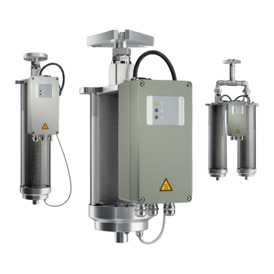
Page 19: Design/Versions
3 Product description 3.2 Design/versions Figure 1: Design BA6820378-03 EN... - Page 20 3 Product description 1 DB100 2 2-hole RM flange*) (in accordance with DIN 2558) including Centellen WS3820 gasket; for DB100 only (optional) 3 4-hole circular flange*) for 1/2″ 4 DIN flange *) (similar to screws including NBR75 gasket DIN 42 562-3) including NBR70 black (optional) gasket in accordance with DIN5305 and including mounting...
-
Page 21: Function Description
3 Product description 3.3 Function description The dehydrating breather is used in oil-insulated transformers, reactors or tap changers for dehydrating the air sucked into oil conservators. Figure 2: Overview 1 Upper air spout 2 Lock nut 3 Mounting flange (configurable) 4 Nut 5 Temperature and humidity sensor 6 Grounding screw 7 Sensor cable and cable protection... -
Page 22: Terminal Box
3 Product description 3.4 Terminal box Figure 3: Connection box 1 LEDs for status display 2 RTC buffer battery (type CR2032) 3 USB service interface 4 Test button 5 Modbus settings (optional) 6 Fuse 7 Supply voltage 8 Cable gland 100...127 V DC / AC 50/60 Hz M20x1.5 (brass/stainless steel) or 200...240 V DC / AC 50/60 Hz 1/2″... -
Page 23: Controller For Silica Gel Heating
3 Product description 9 Signaling relay 10 Analog output 1 (temperature) Analog output 2 (humidity) 0…20 mA or 4…20 mA 11 RS485 interface (optional) 3.5 Controller for silica gel heating The MTRAB dehydrating breather is delivered with an alpha controller, beta controller or gamma controller. The recommended application areas for the different versions of the dehy- drating breather are specified in the Applications table (see [►Section 12.2, Page 108]). -
Page 24: Self-Monitoring Function
3 Product description 3.7 Self-monitoring function The dehydrating breather has a self-monitoring function. If an error occurs in the device, this is indicated by the different lighting patterns of the LEDs on the front of the terminal box, and also output by the "device error" signaling relay [►Section 3.4, Page 22], position . -
Page 25: Test Button
3 Product description 3.10 Test button The test button can be used to force a device test to be performed (Test but- ton [►Section 10.3, Page 94]). 3.11 Safety markings and nameplate Figure 5: Safety markings BA6820378-03 EN... - Page 26 3 Product description Risk of burns! See the chapter Operation [►Section 8, Page 79] Warning symbol on the nameplate: Danger! Observe notices in the operating instructions re- garding supply voltage; see nameplate in the chapter Commissioning [►Section 7, Page 76] Sticker on the dust protection tube: Remove protective cap! See the section Removing the red protective cap [►Section 5.5, Page 49]...
-
Page 27: Packaging, Transport And Storage
4 Packaging, transport and storage 4.1 Purpose The packaging is designed to protect the packaged product during transport, loading, unloading and during periods of storage in such a way that no detri- mental changes occur. The packaging must protect the goods against per- mitted transport stresses such as vibration, knocks and moisture (rain, snow, condensation). - Page 28 4 Packaging, transport and storage Every delivered shipment must be checked for the following by the recipient before acceptance (acknowledgment of receipt): ▪ Completeness based on the delivery slip ▪ External damage of any kind. The checks must take place after unloading, when the box or transport con- tainer can be accessed from all sides.
-
Page 29: Storage Of Shipments
4 Packaging, transport and storage 4.5 Storage of shipments When selecting and setting up the storage location, ensure the following: ▪ Store the product and accessories in the original packaging until installa- tion. ▪ Protect stored goods against moisture (rain, flooding, water from melting snow and ice), dirt, pests such as rats, mice, termites etc. - Page 30 4 Packaging, transport and storage 2. Place on an open flat surface so that the glass cylinder of the desiccant container is exposed. Figure 6: DB100 / DB200 removal CAUTION Risk of injury! Improper removal of the device from the shipping container can lead to injuries.
- Page 31 4 Packaging, transport and storage To remove the DB200D / DB200G dehydrating breather from the packaging, proceed as follows: 1. Grasp the connection pipe and both air exhausts on the DB200D / DB200G as shown in the image. Figure 7: DB200D / DB200G removal 2.
- Page 32 4 Packaging, transport and storage Figure 8: Setting down the DB100 / DB200 Figure 9: Setting down the DB200D / DB200G BA6820378-03 EN...
-
Page 33: Mounting
5 Mounting This chapter describes how to correctly mount the device. CAUTION Risk of injury! Risk of injury due to shattered glass cylinder of the desiccant container as the result of mechanical tension or jolts! ► Wear safety gloves during assembly in addition to the protective equip- ment that must always be worn. - Page 34 5 Mounting ▪ Prevent any sources of interference in the pipe between the MTRAB and the expansion tank (conventional dehydrating breather, non-return valves, etc.). Figure 11: MTRAB pipe dips and interference sources ▪ Do not install MTRAB dehydrating breathers in parallel. Figure 12: MTRAB parallel installation BA6820378-03 EN...
-
Page 35: Checking The Connecting Flange On The Transformer
5 Mounting ▪ Do not install the MTRAB dehydrating breather close to a sprinkler system that sprays upwards from below. ▪ Do not clean the MTRAB dehydrating breather with spray water from be- low. Figure 13: Sprinkler system and spray water 5.2 Checking the connecting flange on the transformer 1. -
Page 36: Preparing The Device
5 Mounting 2. Check the sealing surface of the counterflange. It must be clean and un- damaged, without any surface damage radiating out from the center. The surface quality of the sealing surface must be suitable for use of the gas- ket. - Page 37 5 Mounting Figure 15: Nut on the upper air spout To prepare the dehydrating breather for mounting, proceed as follows: 1. Remove the red protective cap from the upper air intake spout. 2. Check that there is a gasket in the air intake spout. Figure 16: Protective cap and gasket 3.
- Page 38 5 Mounting NOTICE Danger of damage to property If a flange is used that is unsuitable for the weight of the device, the flange may fail. ► Only use the 2-hole RM flange for the DB100. Figure 17: Insertion of MTRAB flange 4.
-
Page 39: Mounting The Device On The Counterflange
5 Mounting 5. For lifting the DB100 / DB200, replace the grounding screw with a lifting eye bolt. Figure 19: Lifting eye bolt 5.4 Mounting the device on the counterflange WARNING Danger of death and damage to property! Danger of death and damage to property due to falling load! ►... -
Page 40: Attaching The Lifting Gear
5 Mounting 5.4.1 Attaching the lifting gear NOTICE Damage to the dehydrating breather The device can become damaged or fall if it is set down vertically on the air exhaust. ► Do not support or set the device down on the air exhaust. To mount the dehydrating breather on the counter-flange, proceed as fol- lows: 1. - Page 41 5 Mounting 2. Lift and upright the DB100 / DB200 as shown in the image. Figure 21: Lifting and uprighting the DB100 / DB200 3. Attach the lifting gear to the lifting eye bolt or pipe connection. Figure 22: Lifting gear BA6820378-03 EN...
-
Page 42: Inserting The Flange Gasket
5 Mounting 5.4.2 Inserting the flange gasket ► Insert the flange gasket. Figure 23: Flange gasket BA6820378-03 EN... -
Page 43: Screwing On The Flanges
5 Mounting 5.4.3 Screwing on the flanges DIN flange (optional) 1. Screw the MTRAB to the transformer counter-flange using the flange (mounting materials contained in the scope of delivery). Figure 24: Screw connection 2. Tighten each screw in turn with approximately 24 Nm. 3. - Page 44 5 Mounting 6. Tighten each screw again with approximately 80 Nm. Figure 25: Screws of DIN flange BA6820378-03 EN...
- Page 45 5 Mounting 4-hole circular flange (optional) 1. Screw the MTRAB to the transformer counter-flange using the flange (mounting materials not included in the scope of delivery). Figure 26: Screws of 4-hole round flange 2. Tighten the screws crosswise with approx. 30% of the torque. 3.
- Page 46 5 Mounting 2-hole RM flange (optional) 1. Screw the MTRAB to the transformer counter-flange using the flange (mounting materials not included in the scope of delivery). Figure 27: Screws of 2-hole RM flange 2. Tighten each screw in turn with approx. 30% of the torque. 3.
-
Page 47: Aligning The Device
5 Mounting 5.4.4 Aligning the device Aligning the device: ► Align the device as desired using the double screw connection after mounting. Figure 28: Alignment of dehydrating breather 5.4.5 Tightening the double screw connection Tightening the double screw connection on the DB100 / DB200: 1. - Page 48 5 Mounting 4. Tighten the locknut again with 250 Nm. Figure 29: Double screw connection on the DB200D / DB200G BA6820378-03 EN...
-
Page 49: Removing The Lifting Gear Again
5 Mounting 5.4.6 Removing the lifting gear again ► Remove the lifting gear again carefully. For DB100 / DB200, replace the lifting eye bolt with the grounding screw including washer. Figure 30: Grounding screw 5.5 Removing the red protective cap NOTICE Dehydrating breather malfunction! The red protective cap blocks air exchange during operation of the dehy- drating breather! - Page 50 5 Mounting ► Remove the red protective cap from the dust protection tube on the bot- tom of the device. Figure 32: Red protective cap BA6820378-03 EN...
-
Page 51: Electrical Connection
6 Electrical connection This chapter describes the correct electrical connection of the device. Ob- serve the following hazard notices prior to opening the device: DANGER Electric shock! Risk of fatal injury due to electrical voltage. Always observe the following safety regulations when working in or on electri- cal equipment. -
Page 52: Wiring Requirement Of Operating Site
6 Electrical connection 6.1.2 Wiring requirement of operating site Note the following when wiring the operating site: ▪ Do not route lines which cause interference (e.g. supply lines) and lines susceptible to interference (e.g. signal lines) in the same cable duct. ▪... -
Page 53: Cable Recommendation
6 Electrical connection Suitable equipment includes isolating devices in accordance with IEC 60947-1 and IEC 60947-3 (e.g. circuit breakers). Note the properties of the relevant circuits (voltage, maximum currents) when selecting the circuit breaker type. In addition, observe the following: ▪... -
Page 54: Routing And Preparing The Cable
6 Electrical connection ▪ The cables used must be flame-resistant in accordance with IEC 60332-1-2 or UL 2556 VW-1. ▪ If both low voltage and extra-low voltage are connected in the device, it must be ensured that the circuits for extra-low voltage and for low voltage in the connection area and in the cable are separated from each other with double insulation. - Page 55 6 Electrical connection To prepare the cable correctly, proceed as follows: 1. Open the terminal box of the dehydrating breather. To do so, unscrew the 4 captive screws on the housing cover. The cover is held on the left-hand side via spring hinges and can be swung open to the left. The cover of the terminal box is grounded with a grounding cable Figure 34: Uninstalling the cover of the terminal box 2.
- Page 56 6 Electrical connection 3. Remove the cable jacket from the relay and analog output cables and strip 7 mm (1/4″) of insulation from the wires 4. Unscrew the leftmost of the three cable glands. Figure 36: Unscrewing the cable gland BA6820378-03 EN...
- Page 57 6 Electrical connection 5. Insert a sufficient length of cable through the cable gland and rubber gas- ket and tighten the cable gland so that moisture from outside cannot pen- etrate the terminal box. Figure 37: Closing the cable gland NOTICE Malfunction Tightening the cable glands too tightly may result in line breaks and short circuits.
-
Page 58: Connecting The Supply Voltage
6 Electrical connection 6.5 Connecting the supply voltage In order to connect the cable for the supply voltage, proceed as follows: 1. Insert the wire for the protective conductor into terminal 1 (PE) and tighten the screw terminal. 2. Insert the wire for the phase/plus into terminal 2 (L+) and tighten the screw terminal. -
Page 59: Connecting The Regeneration Signaling Relay
6 Electrical connection 6.6 Connecting the regeneration signaling relay WARNING Electric shock! The regeneration and device error signaling contacts may both be operated either with safety extra-low voltage (SELV) or with low voltage. For electrical safety reasons, mixed operation with both SELV and low voltage is not permitted. In order to connect the cable for transmitting the regeneration signal (changeover contact), proceed as follows: 1. -
Page 60: Connecting The Device Error Signaling Relay
6 Electrical connection 6.7 Connecting the device error signaling relay WARNING Electric shock! The regeneration and device error signaling contacts may both be operated either with safety extra-low voltage (SELV) or with low voltage. For electrical safety reasons, mixed operation with both SELV and low voltage is not permitted. -
Page 61: Connecting Analog Outputs
6 Electrical connection 6.8 Connecting analog outputs Analog 1 Analog 2 Temperature Humidity The analog outputs are active outputs. Observe the load resis- tance of 0...600 Ω. In order to connect the cable for transmitting analog signal 1 for the tempera- ture, proceed as follows: 1. - Page 62 6 Electrical connection The analog output signal is a 4…20 mA signal by default (0… 20 mA optional). BA6820378-03 EN...
-
Page 63: Connecting The Rs485 Interface And Configuring Modbus (Optional)
6 Electrical connection 6.9 Connecting the RS485 interface and configuring Modbus (optional) The MESSKO® MTRAB® can be connected with a SCADA system via the RS485 interface. This is designed as a 4-conductor system (full duplex), but can also be integrated into a 2-conductor system (half duplex). RS485 interface assignment for Modbus RTU PINs 4-conductor system... - Page 64 6 Electrical connection To connect the cables for integration into a 4-conductor system, proceed as follows: 1. Insert the wire for Rx+ into screw terminal "1 Rx+" and tighten. 2. Insert the wire for Rx- into screw terminal "1 Rx-" and tighten. 3.
-
Page 65: 2-Conductor Half Duplex
6 Electrical connection 6.9.2 2-conductor half duplex Figure 44: 2-conductor system To connect the cables for integration into a 2-conductor system, proceed as follows: 1. Insert the wire for D+ into screw terminal "1 D+" and tighten. 2. Insert the wire for D- into screw terminal "1 D-" and tighten. 3. -
Page 66: Notes On Connecting To The Mr Sensor Bus
Damage to the device or sensor. Connect all of the sensors to the potential equalization rail to avoid circulating currents over the MR sensor bus. ▪ The MR sensor bus uses Modbus in a 2-wire configuration (2W). The 4- wire configuration (4W) is not supported. BA6820378-03 EN... - Page 67 (each of 680 Ω in accordance with the Modbus specification). No addi- tional pull-up/pull-down resistors are needed. CPU-COM2 Com. (C) D0 (A) D1 (B) Sensor 1 Com. (C) D0 (A) D1 (B) Sensor x Com. (C) D0 (A) 120 Ω D1 (B) Figure 46: MR sensor bus BA6820378-03 EN...
-
Page 68: Messko® Mtrab® 2.5
6 Electrical connection 6.9.4 MESSKO® MTRAB® 2.5 If you would like to use a MESSKO® MTRAB® 2.5 sensor, you must con- nect the sensor to the RS485 plug terminals on the sensor bus. CPU-COM2 Com. (C) D0 (A) D1 (B) MTRAB 2.5 D+ | Rx+ D- | Rx-... - Page 69 6 Electrical connection You must enable the half-duplex operating mode on the sensor by switching the "Duplex mode" switch to the "HALF" setting. If the MESSKO® MTRAB® 2.5 sensor is the only bus device or the last bus device, you must activate the sensor terminating resistor by switching the "BUS termination 120 ohms"...
-
Page 70: Modbus Settings
6 Electrical connection 6.9.5 Modbus settings Figure 49: RS485 settings Half-duplex or full-duplex operation ® ® To set the MESSKO MTRAB for half-duplex operation, proceed as follows: ► Set the "Duplex mode" switch to the "HALF" position. ® ® To set the MESSKO MTRAB for full-duplex operation, proceed as follows: ►... -
Page 71: Closing The Terminal Box
6 Electrical connection Changing the Modbus address of the device The Modbus address of the device is set to 3 (ADR switch position 3) as standard. In this setting, the transmission speed is 19,200 baud and the par- ity is "EVEN". The Modbus address of the device can be changed via the "ADR"... - Page 72 6 Electrical connection 1. Ensure that the grounding cable to the housing cover is not damaged when closing the terminal box. Figure 51: Visual inspection 2. Set the cover of the terminal box properly on the bottom of the housing and then tighten the four housing screws. Figure 52: Closing the terminal box cover BA6820378-03 EN...
-
Page 73: Additional Device Grounding
6 Electrical connection 6.11 Additional device grounding The device has an additional grounding point which, if required, can be con- nected to the ground potential. The material for establishing this additional ground connection is not included in the scope of delivery. ►... -
Page 74: Ground Test
6 Electrical connection 1. Conduct a test between the protective conductor (PE) at terminal 1 and neutral conductor (N-) at terminal 3. 2. Conduct a test between the protective conductor (PE) at terminal 1 and phase (L+) at terminal 2. Figure 54: Dielectric test If the device is not operated in the European Community, the national regulations for conducting the dielectric test in the re-... - Page 75 6 Electrical connection To perform the ground test, proceed as follows: ► Feed the test current in at the fixing screw of the grounding cable using a constant current source and measure the voltage between the measure- ment point and the protective conductor connection at terminal 1. ð...
-
Page 76: Commissioning
7 Commissioning NOTICE Damage to the device! Damage to the electronics of the dehydrating breather due to incorrect sup- ply voltage! ü Make sure that the correct supply voltage in accordance with the name- plate is present on the energized miniature circuit breaker. ►... -
Page 77: Device Self Test During Commissioning
7 Commissioning 7.1 Device self test during commissioning The MTRAB LED signaling during commissioning is explained in the follow- ing. Observe the following legend for the respective LED state. Figure 57: LED legend 1 LED lights up 2 LED flashes 3 LED off The device performs a device self-test (approx. -
Page 78: Adjusting Modbus Settings
7 Commissioning After concluding the self-test, the green power LED remains lit. If an error has been detected, this is indicated via the LEDs (see Error messages and troubleshooting [►Section 9, Page 83]). Figure 59: Error-free operation An expanded test triggered by the user can be started using the test button (see "Test button"... -
Page 79: Operation
8 Operation During error-free operation, the green power LED is constantly lit and the red error LED is off. Figure 60: Error-free operation If LED and/or LED issues a lit and flashing signal and the device mal- function LED is off, follow the instructions in the chapter Status messages [►Section 9.2, Page 87]. - Page 80 8 Operation CAUTION Slipping hazard! Danger to health! ► In case of temperatures at or below freezing, any escaping condensa- tion can lead to icy ground beneath the device. In this case, do not step under the device. NOTICE Malfunction due to contaminated silica gel Prevent the silica gel becoming contaminated due to direct contact with the insulating fluid.
-
Page 81: Mtrab With Gamma Controller (Db200G Only)
If the fuse fails, it can easily be replaced (Fuse [►Section 9.3, Page 88]). If it happens again, please consult "MR Service & Complaint" [►Section 9, Page 83]. A device version is avail- able that eliminates the occurrence of overvoltages. Overvolt- age protection can also be retrofitted by replacing a circuit board. - Page 82 8 Operation Figure 62: Ball valve 1 Switch 2 Ball valve 3 Display 4 Ball valve control cable BA6820378-03 EN...
-
Page 83: Error Messages And Troubleshooting
(failsafe) picks up again after all errors have been acknowledged. If an error occurs that you cannot remedy yourself, please contact: Maschinenfabrik Reinhausen GmbH MR Service & Complaint Falkensteinstrasse 8 93059 Regensburg Germany E-mail: service@reinhausen.com... - Page 84 9 Error messages and troubleshooting Figure 63: LEDs 1 Green LED 2 Yellow LED 3 Red LED BA6820378-03 EN...
-
Page 85: Error Messages
9.1 Error messages The individual errors and possible corrective actions are listed in the follow- ing table. If a suitable corrective action cannot be found in this table, please contact MR Service & Complaint [►Section 9, Page 83]. Green Yel-... - Page 86 9 Error messages and troubleshooting Green Yel- Error Action Internal error General device error. Contact MR Service & Complaint [►Section 9, Page 83]. Left-hand position ball Check whether the ball valve valve error (DB200G switch [►Section 8.1, Page 81] is only) in the "AUTO"...
-
Page 87: Status Messages
9 Error messages and troubleshooting Figure 64: Tests 1 Filter-heater supply cable (op- 2 Test button tional / HT version only) 3 Silica-gel heating supply cable 4 Sensor-cable socket 5 Sensor-cable screw connection 6 Sensor cable 9.2 Status messages The individual status messages that do not have an error as the cause are listed in the following table. -
Page 88: Fuse
= LED ON = LED FLASHING 9.3 Fuse If the fuse fails again, please consult MR Service & Complaint [►Section 9, Page 83]. A device version is available that elimi- nates the occurrence of overvoltages. Overvoltage protection can be retrofitted by replacing a circuit board. - Page 89 9 Error messages and troubleshooting 2. Open the terminal box of the dehydrating breather (see [►Section 6.4, Page 54]). To do so, unscrew the 4 captive screws on the housing cover. Open the cover of the terminal box. Figure 65: Removing the fine-wire fuse 3.
-
Page 90: Replacing The Battery (Cr2032)
9 Error messages and troubleshooting 7. Replace the safety cover. Figure 66: Inserting the fine-wire fuse 8. Close the terminal box again (see [►Section 6.10, Page 71]). 9.4 Replacing the battery (CR2032) If the following LED signaling arises, the CR2032 battery in the device is to be replaced. -
Page 91: Contaminated Silica Gel
9 Error messages and troubleshooting To replace the CR2032 battery in the device, proceed as follows: ü New battery is available. ü The device and system peripherals have been de-energized and mea- sures have been taken to ensure that they cannot be switched back on. 1. - Page 92 In the event of the device being flooded, contact Maschinenfabrik Rein- hausen Service. Service will replace the silica gel and clean the device. Al- ternatively, you can request detailed documentation on replacing the silica gel. Maschinenfabrik Reinhausen GmbH MR Service & Complaint Falkensteinstrasse 8 93059 Regensburg Germany E-mail: service@reinhausen.com E-mail: complaint@reinhausen.com...
-
Page 93: Maintenance, Inspection And Care
▪ Check the display of the LEDs. ▪ Use the test button for checking the signaling paths (see next section). ▪ In the event of questions and discrepancies, contact: Maschinenfabrik Reinhausen GmbH MR Service & Complaint Falkensteinstrasse 8 93059 Regensburg Germany E-mail: service@reinhausen.com or complaint@reinhausen.com... -
Page 94: Test Button
10 Maintenance, inspection and care 10.3 Test button If there was an error on the MTRAB, this must be acknowl- edged prior to conducting a function test. If several errors were present, these are to be acknowledged individually one after the other. -
Page 95: Quick Test
10 Maintenance, inspection and care Figure 69: Test button 10.3.1 Quick test Gree Yel- Humidity level Action ≤10% R.H. Humidity OK. ≤10% R.H. Humidity OK. Regeneration imminent. ≤10% R.H. Humidity OK. Regeneration performed within the last 7 days. >10% and <20% Humidity OK. - Page 96 Check the installation situation. Are all transition points of the piping still sealed tightly? Contact MR Service & Complaint [►Section 9, Page 83] if necessary. >40% R.H. WARNING! Humidity too high.
- Page 97 10 Maintenance, inspection and care Starting a quick test in normal operation ü Device is not in the regeneration process (the silica gel is not being heat- dried; the yellow LED is off). ► Briefly press the test button (hold down for ≤ 3 seconds). ð...
-
Page 98: Long Test
10 Maintenance, inspection and care 10.3.2 Long test NOTICE Incorrect messaging! When performing the long test, the failsafe relay will be activated for test purposes. ► Inform the control room that the failsafe relay will be activated. Figure 71: LED signaling during the long test BA6820378-03 EN... - Page 99 10 Maintenance, inspection and care Starting a long test in normal operation ü Device is not in the regeneration process (the silica gel is not being heat- dried; the yellow LED is off). 1. Press the test button for a longer period and then release (hold down for > 3 seconds).
-
Page 100: Mset Mtrab Data Logger Software (Optional)
10 Maintenance, inspection and care 7. On an MTRAB DB200G device (gamma control), check whether the ball valve moves to the opposite position and back again. While doing so, monitor the display on the front of the ball valve [►Section 8.1, Page 81]. - Page 101 10 Maintenance, inspection and care Figure 73: Spray water Only use a damp cloth and mild cleaning agent to clean the device when needed. BA6820378-03 EN...
-
Page 102: Disposal
11 Disposal Observe the national disposal regulations in the country of use. BA6820378-03 EN... -
Page 103: Technical Data
12 Technical data 12.1 Technical data Operating conditions Location of use Indoors and outdoors Contamination level Relative humidity (operation and Inside the connection box: 5 to 95% (non-con- storage) densing) Ambient temperature DB100/200/200D: 0...+70°C / -50...+70°C HT version*; DB200G: 0...+70°C / -20...+70°C HT version*; It's will*) HT version for applications in cold re- gions, i.e. -
Page 104: Technical Data
12 Technical data Design types Flange connection Flange optional; see dimensional drawings and design; Further customer-specific flanges on request; 2-hole RM flange only for DB 100 Desiccant Only use special colorless, non-toxic silica gel (silicon dioxide) sold by Messko GmbH; See application table for volume Power supply Nominal voltage... - Page 105 12 Technical data Connection box Connection terminals Supply connection, relay, analog outputs: 1.5...4 mm , AWG11-15 (solid or flexible), tight- ening torque 0.5...0.6 Nm RS485 interface: 0.14...1.5 mm , AWG15-26 (solid or flexible), tightening torque 0.25 Nm Status display 3 LEDs (green - operation indicator, yellow - regeneration heating, red - device malfunction) visible from the outside;...
- Page 106 12 Technical data Signaling contacts Reliable switching capacity 240 V AC, 8 A (IEC 61810, 100,000 switching cycles); 240 V AC, 10 A, 2000 VA (UL 508, 30,000 switching cycles); 30 V DC, 8 A, 240 W; 240 V DC, 300 mA Maximum switching capacity In accordance with IEC 60076-22-7, 1,000 switching cycles: 230 V AC, 1840 VA / cos phi > 0.5 250 V AC, 2,500 W / resistive load 24 V DC, 192 W / resistive load Analog outputs (active)
- Page 107 12 Technical data Options Offshore Connection box in accordance with the require- ments of DIN EN ISO 12944-9 with corrosion class CX; Offshore flange version Cable gland stainless-steel version (grade 1.4404) Insect grille See dimensional drawings in attachment 7 SED 6356099 Cable protection Protects the cable from damage such as ani- mal bites, designed as a spiral coiled hose...
-
Page 108: Application Table
12 Technical data Standards and directives Electrical safety IEC 61010-1:2010 Safety requirements for electrical measure- ment and control and regulation equipment and UL 61010-1 laboratory instruments CAN/CSA-C22.2 No. ▪ Protection class I 61010-1:2012 ▪ Overvoltage category III ▪ Contamination level 2 Electromagnetic compatibility IEC 61000-6-5, IEC/KC 61000-6-2, IEC/KC 61000-6-4, FCC 47 CFR Part 15B, ICES-003... - Page 109 12 Technical data Application MTRAB type Silica gel Phase shifter > 200 MVA DB200D-T or 2x 4.4 kg DB200T Reactors ≤ 40 MVAr DB100T 1.1 kg Reactors > 40 Mvar DB200T 2.2 kg ≤ 200 Mvar Reactors > 200 MVAr DB200D-T or 2x 4.4 kg DB200T...
-
Page 110: Dimensional Drawings
13 Dimensional drawings For dimensional drawings, refer to the following pages. Drawing No. Dehydrating Version pen- breather ® SED 6653712 MTRAB Flange connections 000 00 ® SED 6356077 MTRAB DB100/ With additional fastening points on 000 00 DB200 the side ®... - Page 111 DIN-Flansch ähnlich / DIN FLANGE SIMILAR TO DIN 42562-3 .75" .08" 120° RM-Flansch nach / RM FLANGE IN ACCORDANCE WITH DIN 2558 .31" Rundflansch für 1/2"-Schrauben / FLANGE FOR 1/ 2" SCREWS .75" .16" Maßangaben MTRAB® Standard-Flanschanschlüsse Serialnummer ...
- Page 112 3.94" optional 5.75" 6.61" 7.48" 1: 1 6.73" .71" M8 x 20 10,5 .41" 4.72" MTRAB-Abmessung mit Flansch / DB100 DB100 DB200 DB200 MTRAB DIMENSIONS WITH FLANGE DIN-Flansch / DIN FLANGE 454,5 [17.89"] 634 [24.96"] 684,5 [27.11"] 781 [30.75"] RM-Flansch / RM FLANGE 458,5 [18.05"] 638 [25.12"] 1/2"-Schrauben / 1/2"...
- Page 113 3.94" optional 5.75" 15.12" 15.98" 1: 1 .71" M8 x 20 10,5 .41" 4.72" MTRAB® DB200D-T mit seitlicher Zusatzbefestigung / SERIAL NUMBER DIMENSION IN mm MTRAB® DB200D-T WITH ADDITIONAL FASTENING POINTS SHEET MATERIAL NUMBER EXCEPT AS Maßzeichnung / DIMENSION DRAWING ...
- Page 115 Kabelführung für Schutzschlauch / DUCTING FOR CABLE PROTECTION 3.94" 5.75" Kabelschutz / 15.98" CABLE PROTECTION 1: 1 1: 1 4.72" MTRAB® DB200D-T mit Kabelschutz (optional) / SERIAL NUMBER DIMENSION IN mm MTRAB® DB200D-T WITH CABLE PROTECTION (OPTIONAL) SHEET MATERIAL NUMBER EXCEPT AS...
- Page 116 3.94" 5.75" 15.98" MTRAB® DB200G mit Gammasteuerung / SERIAL NUMBER DIMENSION IN mm MTRAB® DB200G WITH GAMMA CONTROL SHEET MATERIAL NUMBER EXCEPT AS Maßzeichnung / DIMENSION DRAWING 101213181M NOTED...
- Page 117 Maß / DIMENSION DB100 DB200 260 [10.24"] 485 [19.10"] 1: 1 optional optional 6.10" 24,8 .98" MTRAB® mit Schutzgitter und Insektenschutzgitter / DIMENSION SERIAL NUMBER IN mm WITH PROTECTIVE GRATE AND INSECT PROTECTIVE GRATE EXCEPT AS MATERIAL NUMBER SHEET ...
-
Page 118: Appendix
14 Appendix 14.1 Modbus RTU Status information Function code "02" for reading the information Value Designation DB100/200/200D DB200G Error present Left SiO2 heating error Right SiO2 heating error DB200D only Voltage supply error Left sensor error Right sensor error DB200D only Right gamma error Left gamma error RTC battery low... - Page 119 14 Appendix Value Designation DB100/200/200D DB200G Right cylinder closed Left regeneration Right regeneration DB200D only Left sensor status Right sensor status DB200D only Analog values (input register) Function code "04" for reading the information MSW/ Value Designation DB100/200/200D DB200G LSW* float32 Left humidity sensor float32...
-
Page 120: Rs485 Communication Settings
14 Appendix Analog values (input register) Function code "04" for reading the information Value Designation DB100/200/200D DB200G sint16 / Left humidity sensor factor 10 sint16 / Left temperature sensor factor 10 sint16 / Right humidity sensor DB200D only factor 10 sint16 / Right temperature sensor DB200D only... - Page 124 Messko GmbH Gewerbegebiet An den Drei Hasen Messko-Platz 1 61440 Oberursel, Germany +49 (0)6171 6398 0 messko-info@reinhausen.com www.reinhausen.com/messko ® ® BA6820378-03 EN - MESSKO MTRAB F0377903 - 08/21 - Messko GmbH 2021 THE POWER BEHIND POWER.
Need help?
Do you have a question about the MESSKO MTRAB and is the answer not in the manual?
Questions and answers