
Related Manuals for WEG PFW03-M08


Summary of Contents for WEG PFW03-M08
- Page 1 Motors | Automation | Energy | Transmission & Distribution | Coatings Power Factor Controller PFW03-M08 User Manual...
- Page 3 User Manual Series: PFW03-M08 Language: English Document: 10006614888 / 01...
-
Page 5: Table Of Contents
4.1 RS485 WIRING DIAGRAM ........................22 4.2 COMPUTER CONNECTION .......................22 4.3 MESSAGE FORMAT AND DATA TYPES OF MODBUS-RTU PROTOCOL ........22 4.4 IMPLEMENTED FUNCTIONS FOR MODBUS-RTU PROTOCOL .............23 4.5 DATA AND SETTING PARAMETERS FOR PFW03-M08 ..............23 4.5.1 Readable Data for PFW03-M08 ....................23 5 TECHNICAL SPECIFICATIONS... -
Page 6: General Information
„ Alarm relay connections: Overcurrent protection is required for alarm relay outputs: 3 Arms gL fuses (IEC 269) or M type fuses (IEC 127) with rated voltage 300 VAC; „ l It is required to use a circuit breaker in order to easily disconnect PFW03-M08 from mains. Circuit breaker should have the following specifications: 3 poles (one pole for each phase), 300 VAC or above rated voltage 1 A or above rated current;... -
Page 7: Receipt Control And Contents Of The Delivery
As a result of these measurements, it activates capacitors in the compensation panel. All user actions can be performed easily using the LCD display and 4 keys on the front panel. PFW03-M08 has an isolated RS485 port. It also has 2 alarm relay and many more features. -
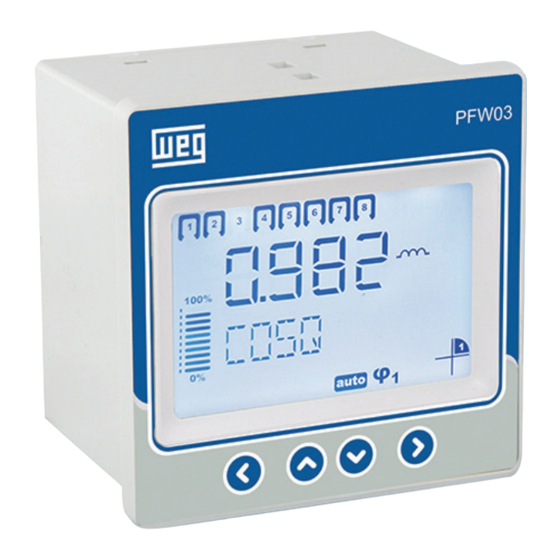
Page 8: Pfw03-M08 Front Panel
5. Target Cos φ. 6. Automatic Mode. 7. Manual Mode. 8. Alarm icon. 9. Communication active icon. 10. Alarm relay icons. 11. The ratio of the steps in the operation to the total step power. 8 | Power Factor Controller - PFW03-M08... -
Page 9: Installation
PFW03-M08 that you have purchased may not include all hardware options specified in the installation manual. This is not issue for the electrical installation. DANGER! Installation and connections of PFW03-M08 shall be performed by qualified persons with respect to the instructions on the user’s manual. DANGER! Do not operate the device before making the connections correctly. - Page 10 Make sure that the power is cut off before connecting voltage and current ends to PFW03-M08. DANGER! Do not remove PFW03-M08 current transformer connections without short circuiting the K-L ends of the current transformer to somewhere else. Otherwise, dangerous high voltages may occur on the secondary ends of the current transformer. The same applies to starting of the device.
- Page 11 Terminal is placed on its housing on PFW03-M08. CAUTION! Consider this warning if PFW03-M08 is used with current transformers. Correct operating threshold values of transformers vary as per the type and size of the current transformers used. Please check that the measured current value is higher than the current threshold specified in the user’s manual of current transformer.
-
Page 12: Wiring Diagrams
Aux. Relay Step Outputs 1…6 Step Outputs 7…12 Current Input Voltage Input RS485 GEN Input Figure 2.6: PFW03-M08 – 3 phase Connection 1 PHASE CONNECTION Source for contactors Step Outputs 1…6 Step Outputs 7…12 Aux. Relay Current Input... -
Page 13: Dimensions
2.4 DIMENSIONS Dimensions are in millimeters. 96.8 65.0 Figure 2.8: Dimensions Power Factor Controller - PFW03-M08 | 13... -
Page 14: Menus
3 MENUS 3.1 “FIRST POWER-ON” SETTINGS The following page is displayed when PFW03-M08 is energized for the “first time” after it is released from the factory. EN G CON1 001.0 IN D 0001 LANGUAGE connectioN target COSq1 1.1.1.1 0.98 0.02... -
Page 15: Basic Settings
The step which activated first, will be the first deactive step if needed; „ 1.2.4.4: This structure can be used in panels with a step power ratio of 1.2.4.4. PFW03-M08 will always activate or deactivate 1st step first. The other steps are used in sequence;... -
Page 16: Advanced Settings
4. Manual Mode: When the manual program is active, the “man” icon appears under the main menu page. This icon indicates that PFW03-M08 is in the manual compensation program. In the main menu screen, manual mode is activated by pressing the down and up keys at the same time. With the up and down keys, move to the desired step and press the right button. -
Page 17: Alarms Settings
„ 3.3) Hysteresis: It is the tolerance value that can be entered between 0.00 - 1.00; „ 3.4) Delay/sec: PFW03-M08 waits for the delay time before giving an alarm when the related alarm parameter exceeds “Low limit” or “High limit” value. Also, PFW03-M08 waits for the delay time again before cancelling an alarm condition when the related alarm parameter returns back in the limits. -
Page 18: Extreme Cases
„ 3.1) High Limit: In this tab high limit can be set. Adjustable from 0 to 600. „ 3.2) Delay/sec: PFW03-M08 waits for the delay time before giving an alarm when the related alarm parameter exceeds “High limit” value. Also, PFW03-M08 waits for the delay time again before cancelling an alarm condition when the related alarm parameter returns back in the limits. -
Page 19: Communication - Rs485 Setting
1. Settings menu. 2. RS485 menu. 3. Baudrate: Communication Signal speed is expressed with “baud” in terms of units. PFW03-M08 communicates with speeds of 1200, 2400, 4800, 9600, 19200 and 38400 bits/second. 4. Slave ID: This is the settings tab for entering the slave id number. Maximum 247 devices may communicate over the same RS485 line. -
Page 20: Clear Menu
“NO” to “YES”. Then, press the left key to store the changes. save To discard the changes: Press the right key to blink the “NO” sign. Then exit the menu using the left key without saving your changes. save 20 | Power Factor Controller - PFW03-M08... -
Page 21: Approval Procedure
Figure 3.11: Instantaneous values 1. Cos φ 2. Power Factor 3. Active Power 4. Reactive Power 5. Apparent Power 6. Voltage 7. Current 8. Frequency 9. THDV 10. THDI Power Factor Controller - PFW03-M08 | 21... -
Page 22: Modbus Protocol
4.2 COMPUTER CONNECTION PFW03-M08 can communicate with PCs via USB-RS85 converter. Figure 4.2: RS485 PC Connection 4.3 MESSAGE FORMAT AND DATA TYPES OF MODBUS-RTU PROTOCOL PFW03-M08, implements modbus RTU protocol. Modbus RTU message format is as follows. Start Address Function Data ≥... -
Page 23: Implemented Functions For Modbus-Rtu Protocol
32-bit integer value. Byte order starts from the lowest byte address as b0, b1, b2 and so on. float: It is a 32-bit floating-point number in IEEE 754 standard. string: Character array in ASCII standard. It is only used for PFW03-M08 device name and PFW03-M08 configuration name variables. 4.4 IMPLEMENTED FUNCTIONS FOR MODBUS-RTU PROTOCOL Function Name... - Page 24 COSQ2 TOLERANCE 32 bit float 40105 STEP ACTIVATION TIME 32 bit integer 40107 STEP DISCHARGE TIME 32 bit integer 40109 BACKLIGHT TIME 32 bit integer SEL 6 40111 LANGUAGE 32 bit integer SEL 7 24 | Power Factor Controller - PFW03-M08...
- Page 25 32 bit integer CLEAR 41001 RESET SETTINGS 32 bit integer 41003 RESET ALARM LIMITS 32 bit integer 41005 FACTORY SETTINGS 32 bit integer SAVE 42001 SAVE CHANGES 32 bit integer Tabela 4.6: Readable Data Power Factor Controller - PFW03-M08 | 25...
-
Page 26: Technical Specifications
Dimensions W144 x H144 x D78 OPERATING TEMPERATURE/ STORAGE TEMPERATURE / RELATIVE HUMIDITY -20°C..+55°C / -30°C..+80°C / maximum 95% No Condensation PROTECTION CLASS Front panel ........: IP40 Rear cover ......... : IP20 26 | Power Factor Controller - PFW03-M08... - Page 27 NOTES Power Factor Controller - PFW03-M08 | 27...
- Page 28 Phone: +39 2 61293535 Phone: +86 519 88067692 info-it@weg.net info-cn@weg.net For those countries where there is not a WEG own operation, find our local distributor at www.weg.net. WEG Group - Automation Business Unit Jaraguá do Sul - SC - Brazil Phone +55 47 3276 4000 automacao@weg.net...
Need help?
Do you have a question about the PFW03-M08 and is the answer not in the manual?
Questions and answers