
Related Manuals for WEG PLC300


Summary of Contents for WEG PLC300
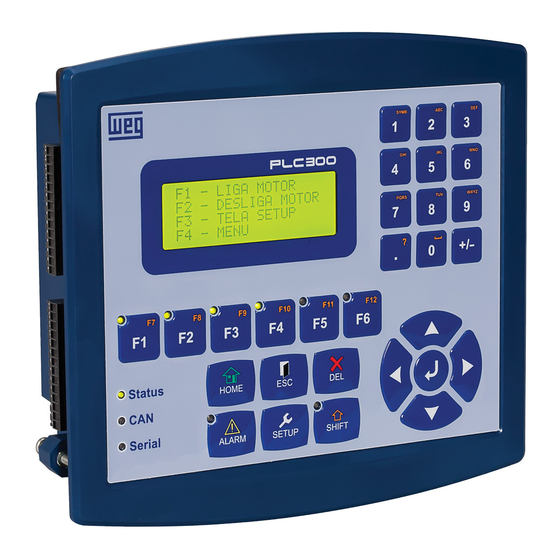
- Page 1 Motors | Automation | Energy | Transmission & Distribution | Coatings Programmable Logic Controller PLC300 User’s Manual...
- Page 3 User’s Manual Series: PLC300 Language: English Document Number: 10004642446 / 00 Models: with and without HMI Publishing Date: 04/2017...
-
Page 5: Table Of Contents
7.14 USER PROGRAM ..................7-10 7.15 SETUP MENU PASSWORD ..............7-10 7.16 WATCHDOG ....................7-11 8 I/O STATUS....................8-1 9 DESCRIPTION OF THE PLC300 OPERATION ........9-1 9.1 SCREEN MANAGEMENT ................9-1 9.1.1 Levels of Access .................. 9-1 9.1.2 Function Keys: F1...F12............... 9-2... - Page 6 Index 9.1.3 Composition of a Screen ..............9-3 9.1.4 Text Component: Writing of Static Text ...........9-3 9.1.5 Numeric Input Component: Data Numeric Input ......9-3 9.1.6 Numeric Output Component: Data Numeric Output ......9-5 9.1.7 Message Component: Output with Texts for a Variable ....9-5 9.1.8 Bar Graph Component: Bar Graph ...........9-6 9.1.9 Text Output ..................
-
Page 7: Safety Instructions
1.2 SAFETY WARNINGS IN THE PRODUCT The following symbols are attached to the product, serving as safety notices: High voltages are present. Components sensitive to electrostatic discharge. Do not touch them. Mandatory connection to the protective earth (PE). PLC300 | 1-1... -
Page 8: Preliminary Recommendations
For the purposes of this manual, qualified personnel are those trained in order to be able to: 1. Install, ground, power up and operate the PLC300 in accordance with this manual and the safety legal procedures in force. 2. Use the protective equipment in accordance with the standards. -
Page 9: Introduction To Plc300
The bootloader is an auxiliary program that executes the main firmware of the PLC300, which, in turn, executes all the functionalities. It is through the bootloader that new firmware can be saved to the PLC300 via USB or Serial. PLC300 | 2-1... - Page 10 WPS. SD memory card (Secure Digital): The PLC300 allows saving data and program, logging events, recipes in a SD memory card. The memory card must be SD type with FAT32 formatting with capacity up to 32G. The faster the card (class of the card), the shorter the recording time. This is important in case of regular variable log recordings, for instance.
- Page 11 Expansion modules: Up to 2 I/O expansion modules can be connected to the PLC300. The following modules are compatible: IOA-01: 1 analog input of 14 bits in voltage and current; 2 digital inputs; 2 analog outputs „...
- Page 12 NOTE: to clean the memory (deletes application, screens, etc.) on versions without HMI (BP and BS), turn on the PLC300 holding the button and release it after the message “Release the Key” appears. Press the button again for two seconds and release.
-
Page 13: Connectors
XC8 – Power input 24 Vdc. S1 – Turn on/off RS-485 termination resistors. Back Back display Battery XC11 XC12 Slot1 Slot2 XC11 – expansion slot 1 XC12 – expansion slot 2 Figure 3.1 (a) and (b) - Position of the connectors PLC300 | 3-1... -
Page 14: Connectors Pinouts
DO9 - fast output 9 (PWM). GNDBB – 0 V digital outputs. VBB – (20...30 Vdc) for the digital outputs. AO1(V) – analog output 1 in voltage. AO1(I) – analog output 1 in current. AO1 – common. 3-2 | PLC300... - Page 15 SHIELD CANH V + (11 to 30 Vdc) XC8 – Power Supply Table 3.5: Function of the pins of the XC8 - Power Supply Function V+ (20 to 28 Vdc) Ground XC4 – Ethernet Ethernet standard connector. PLC300 | 3-3...
- Page 16 Connectors 3-4 | PLC300...
-
Page 17: Connections
Connections 4 CONNECTIONS 4.1 SUPPLY The PLC300 must be powered by a power supply of 24 Vdc ± 15 % with capacity of at least 500 mA. The grounding connection is important. Figure 4.1: XC8: Power connector of the PLC300 4.2 CAN NETWORK... -
Page 18: Digital Outputs
Those configurations should be performed via WPS. 4.4 DIGITAL OUTPUTS The PLC300 has eight insulated and protected digital outputs, besides a fast PWM output that can generate pulses of up to 300 kHz with variable duty cycle from 0 to 100 %. -
Page 19: Analog Input
4.5 ANALOG INPUT The analog input AI1 is differential, 12 bits, and can read signals from a voltage or current source. If the signal source is far from the PLC, it is advisable to use a shielded cable. PLC300 | 4-3... -
Page 20: Analog Output
20 mA, for a resistive load lower or equal to 500 Ω. The voltage and current outputs can be used simultaneously, but obviously with the same value, since they are the same output, just in different ways. 4-4 | PLC300... -
Page 21: Encoder Input
Figure 4.5: Example of connection of the analog output (XC2) 4.7 ENCODER INPUT The PLC300 features an insulated input for differential encoder, with its own supply of 5 or 12 V. The maximum frequency of the pulses is 100 kHz. Maximum length of the encoder cable: 30 m. - Page 22 The signals A, B and Z can be used to fast counting and interrupts, also in 24 V. Encoder PNP: if an encoder with PNP outputs is used, resistors of 1 K ohm must be connected from the used signals to the 0 V. E.g.: PNP encoder with A and B signals. 4-6 | PLC300...
-
Page 23: Rs-232 Interface
All the operations performed by the USB via WPS, can be done by this interface, i.e., programming, monitoring, setup, etc. The configuration of this interface is done by the setup menu. ATTENTION! Do not connect the GND of the RS232 (pin 11) to the ground of the system. PLC300 | 4-7... -
Page 24: Rs-485 Interface
RS232 Figure 4.8: Connecting the RS-232 Note: For further information, consult the manual for serial communication, available for download on the website: www.weg.net. 4.9 RS-485 INTERFACE Insulated, multipoint serial interface intended for network communication. It can operate as master or slave with the Modbus RTU protocol. -
Page 25: Ethernet Interface
Twisted pair Figure 4.9: Connecting the RS-485 Note: For further information, consult the manual for serial communication, available for download on the website: www.weg.net. 4.10 ETHERNET INTERFACE See the Modbus TCP communication manual, available for download on the website: www.weg.net. - Page 26 Connections 4-10 | PLC300...
-
Page 27: Description Of The Keys
By pressing the <ALARM> key, the list of active alarms is shown and the LED stops flashing, indicating the acknowledgement of the alarm. If the alarm is normalized, it leaves the list of active alarms and goes to the alarm history, which can be seen by pressing <SHIFT><ALARM>. PLC300 | 5-1... - Page 28 Three functions can be accessed by means of this key: when pressed normally, it enters the status of the I/Os (Status PLC300); when pressed for t>3s, it enters the PLC300 setup; when pressed after the <SHIFT> key, it shows the opening screen of the product, where you can see the firmware version.
-
Page 29: Expansions
Expansions 6 EXPANSIONS Up to two expansions can be connected to the PLC300. These expansions are the I/O type of the CFW11 (Frequency Inverter WEG 11). The detection of the expansions is automatic and the status of the I/Os can be checked by pressing SETUP and browsing with the arrows <>... - Page 30 NOTE: For the expansion modules IOE-01, IOE-02 and IOE-03, the value read in AI101...105 or AI201...205 will be the temperature in °C multiplied by 10, that is, for a temperature of 32.1 °C, the value read will be 321. For further information, refer to the expansion module installation guide. 6-2 | PLC300...
-
Page 31: Configuration Of The Plc300
Configuration of the PLC300 7 CONFIGURATION OF THE PLC300 Setup Function via HMI keyboard In order to access the setup function via keyboard, press the <SETUP> key until an internal screen appears and prompts to enter a password. S E T U P T y p e 4 d i g P a s s w o r d . -
Page 32: Language Selection
Configuration of the PLC300 7.2 LANGUAGE SELECTION It allows selecting the language of internal screens and messages between Portuguese (PT) or English (EN). The home screen shows the current language 'PT' or 'EN'; by pressing any arrow, the language is switched. -
Page 33: Ioa Card (Aos)
AOs 101 and 102 are the AOs 1 and 2 of the IOA card installed in the slot 1 of the PLC300, and the AOs 201 and 202 are the AOs 1 and 2 of the IOA card installed in the slot 2. -
Page 34: Rs-485 Setup
It is possible to configure the baud rate, the parity and the number of stop bits, the mode (master/slave/telegram ) and the address of the PLC300 in a Modbus RTU network by means of the RS-485 serial interface. R S 4 8 5 S e t u p - - - - - - - - - - - - - - - - - - - - >... -
Page 35: Can Setup
<ESC> returns to the main menu of the setup. 7.10 CAN SETUP It is possible to configure the baud rate and the address of the PLC300 in a CANopen network, through the CAN Interface. The arrows <> and <> select the option to be changed. By pressing <ENTER>, the cursor flashes in the operating mode to be changed. -
Page 36: Mb Tcp Setup
IP Address: 4 bytes of address that identify the PLC300 in the IP network; Subnet: 4 bytes that identify the subnet to which the PLC300 belongs in the IP network; Gateway: 4 address bytes that identify the default gateway to access other subnets in the IP network;... -
Page 37: Sd Card - Backup Hmi Version
<ESC> returns to the main menu of the setup. 7.13 SD CARD – BACKUP HMI VERSION It allows to record (PLC300 -> SD card) or upload (SD card -> PLC300) a resource, setup configurations and firmware in the SD card connected to the PLC300. - Page 38 Possible error causes: Invalid or nonexistent files. „ Review of the files incompatible with the firmware version of the PLC300. „ Folder with the equipment number different from that configured in the setup. „ SD card without space for writing or with writing protection activated.
- Page 39 In order to protect the user’s data, a protection password for the SD card can be set on the WPS. In the case of the PLC300 Blind (without HIM), the unlocking must be done by means of the menu ‘Communication-> Online Commands’, on the WPS.
-
Page 40: User Program
Configuration of the PLC300 The menu output is executed by timeout, i.e., in about 10 s without operation, the PLC300B display will show the status of the I/Os again. EDITING OF THE EQUIPMENT NUMBER (BLIND VERSION, WITHOUT HMI) To edit the number of the equipment, press the key for some seconds, then the cursor flashes on the number. -
Page 41: Watchdog
The arrow <> or <DEL> keys work as backspace. 7.16 WATCHDOG It allows configuring the watchdog of the PLC300. W a t c h d o g - - - - - - - - - - - - - - - - - - - - >... - Page 42 Configuration of the PLC300 <ENTER> accepts the changed value. <ESC> aborts. <ESC> returns to the main menu of the setup. 7-12 | PLC300...
- Page 43 D O 9 - P W M F R E Q U E N C Y : 1 0 . 1 2 k H z D U T Y C Y C L E : 8 4 . 9 0 % PLC300 | 8-1...
- Page 44 S 1 03: = / = (F P ) By pressing the key <> again, the other two temperatures are shown: [ - S T A T U S P L C30 0 S 1 0 4 : S 1 0 5 : 8-2 | PLC300...
- Page 45 I/O Status Status of the Ethernet Interface You may check on the last screen, the MAC Address of the PLC300 and its current IP address. [ - S T A T U S P L C30 0 M A C A d d r e s s 38 -31 - A C - 0 0 - 0 0 - 0 0 I P : 1 9 2 .
- Page 46 2 0 . 0 m A A O 1 0 1 : - 1 0 . 0 V 2 0 . 0 m A A O 1 0 2 : 9 . 0 V 1 8 . 0 m A 8-4 | PLC300...
- Page 47 S 1 0 5 : Status of the Ethernet Interface You may check on the last two screens, the MAC Address of the PLC300 and its current IP address. M A C A d d r e s s :...
- Page 48 I/O Status 8-6 | PLC300...
-
Page 49: Description Of The Plc300 Operation
D e f a u l t H O M E . User Program When the PLC300 is energized, it is checked if there is a valid ladder program in the memory; if any, the program is started immediately. 9.1 SCREEN MANAGEMENT Up to 512 screens can be used by the user. -
Page 50: Function Keys: F1
Description of the PLC300 Operation necessary to have a password of higher level or equal to the level 5. In addition to the property of the level of access, you can set the ‘auto logoff’, which resets the password entered to access level prior to the screen that has just left. -
Page 51: Composition Of A Screen
Description of the PLC300 Operation 9.1.3 Composition of a Screen The screen can be composed by Text, Input, Output, Message and Bargraph elements. Each element is placed in a certain position, forming a layout defined by the user. Example of user’s screen: F 1 : G o t o s c r e e n 5 R a d i u s : 1 . - Page 52 Description of the PLC300 Operation Only numbers are allowed, including sign and decimal point. After typing the number, press <ENTER> to update the value. The <DEL> key deletes the character under the cursor. <ESC> exits without changing the value. Properties of the input component: line (y), column (x), width, data type, maximum and minimum and number of decimal digits.
-
Page 53: Numeric Output Component: Data Numeric Output
Description of the PLC300 Operation in the WORD variable, the typed value is truncated (not rounded) and as this is a integer „ number, the stored value is multiplied by 1000, which is the power 10 , where 3 is the number of decimal places. -
Page 54: Bar Graph Component: Bar Graph
“Friday” “Saturday” In this example, the PLC300 will show the texts, which are the days of the week, for variable values between 0 and 6; if the content of the variable is out of these values, the proper number will be shown. -
Page 55: Text Output
A maximum of 4 bargraphs can be placed on each screen. 9.1.9 Text Output Shows text (string) on the ‘Ouput’ function of the screens of the PLC300 with HMI. This option only accepts STRING. The string is terminated with the NULL (0) character and is shown in one line of the display, being then limited to 20 characters. - Page 56 Description of the PLC300 Operation 9-8 | PLC300...
-
Page 57: Alarms
The alarms are an important tool in process automation, allowing the user to monitor its plant, checking critical points and signaling to the operator. In the PLC300, the alarms can be programmed by the user, being activated by a bit marker that can be set on the ladder. -
Page 58: User Alarms
It is possible to show the content of a variable, formatted, in the second line of the alarm. 10.3 ALARM SCREENS The PLC300 has two internal screens that help in the verification of the alarms, both internal and the user’s. The List of Active Alarms and the Alarm History. - Page 59 N : 1 6 / 1 0 / 0 9 13: 4 0 : 23 In addition to the information already explained in the active alarms, the date and time in which the alarm was normalized appear on the fourth line. PLC300 | 10-3...
- Page 60 The alarm history is retentive, i.e., it is kept when you disconnect the equipment. The history is deleted if the <DEL> key is pressed for 2 s or more and confirmed by pressing ‘Y’. The history is also deleted when transmitting a project by the WPS. 10-4 | PLC300...
-
Page 61: Operation Of The Leds
Operation of the LEDs 11 OPERATION OF THE LEDS The PLC300 has 3 bicolor LEDs, on the keyboard left, that are repeated on the back panel of the equipment. These LEDs inform status on the PLC300 and the CAN and serial networks. - Page 62 Operation of the LEDs 11-2 | PLC300...
-
Page 63: Battery Replacement
Battery Replacement 12 BATTERY REPLACEMENT When the PLC300 generates a low battery alarm, or if there isn’t HMI, and the Status LED flashes in red rapidly, it’s time to replace the battery. The battery used is the CR2032 of 3 V. - Page 64 Battery Replacement Figure 12.2: Insertion of the new battery 12-2 | PLC300...
-
Page 65: Description Of The Models
Description of the Models 13 DESCRIPTION OF THE MODELS The PLC300 is available in six different models. With or without HMI; standard or plus and one version with HMI, but without the frontal overlay membrane, where the user can customize the appearance of the PLC, following specifications in document 1000990528, available for download on the website: www.weg.net. - Page 66 Description of the Models 13-2 | PLC300...
-
Page 67: Self-Test
Self-test 14 SELF-TEST You can execute internal routines of self-test in the PLC300. The way you enter this test is different for some models due to the presence or not of the HMI. How to enter the self-test: In the models with HMI (HP, HS, HSC and HPC), the PLC must be turned on with the F6 „... - Page 68 Self-test 14-2 | PLC300...
-
Page 69: Technical Specifications
Technical Specifications 15 TECHNICAL SPECIFICATIONS Supply: Voltage: 24 Vdc ±15 %. Consumption of the PLC300 in 24 V: 250 mA. Approximate consumption of each expansion: 30 mA. Operating temperature 0 °C to 50 °C. Degree of protection IP65. DI1 to DI10 Digital Inputs: Bidirectional inputs. - Page 70 1 Mbps and configuring the minimum Event Time rate, that is, 1 ms (one millisecond), we have a delay of up to 2 ms (two milliseconds) until the information reaches the PLC300. It must also be considered the scan cycle of the user’s program.
-
Page 71: Standards Met
Dynamic allocation of the area of application, markers, screens and alarms. Scan Cycle for 1000 Program steps For a simple program, done with 500 lines with contacts and coils, which resulted in 1000 instructions, the PLC300 presents the following characteristics: Scan cycle, by KB of program: 133 µs/KB. „... - Page 72 Technical Specifications 15-4 | PLC300...
-
Page 73: Dimensions
Dimensions 16 DIMENSIONS 56.65 (2.23) 49.35 210 (8.26) (1.93) 187.15 (7.36) PLC300 | 16-1... - Page 74 Dimensions 52.53 (2.06) 187.13 (7.37) 174.65 (6.87) Ø 4.8 (0.19) Figure 16.1: Dimensions of the PLC300 16-2 | PLC300...
-
Page 75: Mechanical Mounting
Mounting on Panel (DIN rail or screw) Figure 16.2: Mounting on panel Mounting on the Panel Door Note: dimensions of the slot for mounting on the panel door: 189 x 152 mm Figure 16.3: Mounting on the panel door PLC300 | 16-3... - Page 76 Dimensions Back view of the panel door: Figure 16.4: Back view of the panel door 16-4 | PLC300...
Need help?
Do you have a question about the PLC300 and is the answer not in the manual?
Questions and answers