Table of Contents
Advertisement
Quick Links
User manual
300489
User manual for the portable ATEX data logger
Rev. 01 valid from:
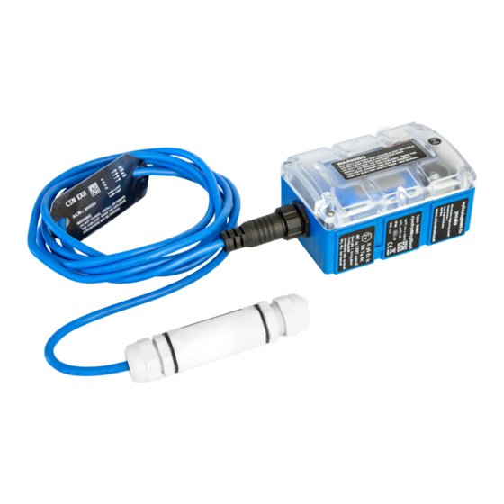
myDatalogNANO Ex
Firmware version: 03v006
l
Modem version: 03v004
l
Server version: 40.1
l
Hardware version: 2.0
l
Microtronics
Engineering GmbH |
Hauptstrasse 7 | 3244 Ruprechtshofen | Austria
Tel +43 2756 77180 23 | Fax +43 2756 77180 33 | support@microtronics.at
www.microtronics.at
Advertisement
Table of Contents

Related Manuals for Microtronics myDatalogNANO Ex


Summary of Contents for Microtronics myDatalogNANO Ex
- Page 1 Rev. 01 valid from: Firmware version: 03v006 Modem version: 03v004 Server version: 40.1 Hardware version: 2.0 Microtronics Engineering GmbH | www.microtronics.at Hauptstrasse 7 | 3244 Ruprechtshofen | Austria Tel +43 2756 77180 23 | Fax +43 2756 77180 33 | support@microtronics.at...
-
Page 3: Chapter 1 Table Of Contents
Chapter 1 Table of contents Chapter 1 Table of contents User manual for the portable ATEX data logger myDatalogNANO Ex Chapter 1 Table of contents Chapter 2 Declaration of conformity 2.1 Declaration of conformity - Appendix Chapter 3 Technical data Chapter 4 General specifications 4.1 Translation... - Page 4 6.2 Scope of supply 6.3 Storage 6.4 Transportation 6.5 Return Chapter 7 Installation 7.1 Dimensions 7.2 Installing the myDatalogNANO Ex 7.2.1 Wall mounting 7.2.2 Top-hat rail assembly 7.2.3 Pipe assembly 7.3 Safety instructions for the cabling 7.3.1 Information on preventing electrostatic discharges (ESD) 7.4 Electrical installation...
- Page 5 8.1 User information 8.2 General principles 8.3 Commissioning the system 8.4 Testing communication with the device Chapter 9 User interfaces 9.1 User interface on the myDatalogNANO Ex 9.1.1 Operating elements 9.1.1.1 Solenoid switch 9.1.1.2 Status LED 9.2 User interface on the myDatanet-Server 9.2.1 Site configuration...
- Page 6 9.2.1.4.2 Calculation 9.2.1.4.3 Alarms 9.2.1.5 Output channels 9.2.1.6 Internal channels 9.2.1.6.1 Basis 9.2.1.6.2 Alarms 9.2.1.6.3 Trigger 9.2.1.7 Alarm settings 9.2.1.8 Basic setting 9.2.1.9 FTP export settings 9.2.2 Device configuration 9.2.2.1 Comments 9.2.2.2 Measurement instrument 9.2.2.3 Device-specific settings 9.2.2.4 GPRS Chapter 10 myDatanet server 10.1 Overview 10.1.1 Explanation of the symbols 10.2 "Customer"...
- Page 7 Chapter 1 Table of contents Chapter 13 Removal/disposal Chapter 14 Troubleshooting and repair 14.1 General problems 14.2 Log entries and error codes 14.2.1 Modem error 14.3 Evaluating the device log 14.3.1 Evaluating the device log on the myDatanet server 14.3.2 Evaluating the device log using DeviceConfig Chapter 15 Spare parts and accessories 15.1 Assembly sets 15.2 Antennas...
-
Page 9: Chapter 2 Declaration Of Conformity
Chapter 2 Declaration of conformity Chapter 2 Declaration of conformity Rev. 01... - Page 10 2.1 Declaration of conformity - Appendix Rev. 01...
- Page 11 Chapter 2 Declaration of conformity Rev. 01...
-
Page 13: Chapter 3 Technical Data
Data type f32(32 Bit floating point) Data transmission By means of GSM/GPRS quad-band modem to the respective myDatanet server The myDatalogNANO Ex is equipped with an integrated SIM chip. Country list profile of the SIM chip: 1 (see www.microtronics.at/footprint) Monthly data t.b.d. - Page 14 The specified values for C and L apply to the sensor connector. The values for L and C indicated on the type cable cable plate of the connection cable must be taken into consideration when determining the maximum cable length. Rev.
-
Page 15: Chapter 4 General Specifications
Chapter 4 General specifications Chapter 4 General specifications The information in this manual has been compiled with great care and to the best of our knowledge. The manufacturer, however, assumes no liability for any incorrect specifications that may be provided in this manual. The manufacturer is not responsible for direct, indirect, accidental or consequential damages which arise from errors or omissions in this manual even if advised of the possibility of such damages. - Page 16 4.4 Ex protection The portable instrument myDatalogNANO Ex designed for use in areas with a zone 2 explosive atmosphere. The following conditions must be adhered to: Only the manufacturer's original spare parts must be used. During installation, it must be ensured that the device is protected against light (e.g. day light, artificial lighting) and it must be installed in such a way that the light resistance requirements as per IEC60079-0 are met.
-
Page 17: General Safety Instructions
Chapter 4 General specifications 4.5 Safety instructions For the connection, commissioning and operation of the myDatalogNANO Ex , the following information and higher legal regulations of the country (e.g. ÖVE), such as valid EX regulations as well as the applicable safety and accident prevention regulations for the respective application case must be observed. -
Page 18: Safety And Preventative Measures For Handling Gsm/Gprs Modems
4.5.3 Safety and preventative measures for handling GSM/GPRS modems Observe the following safety and preventative measures during all phases of installation, operation, maintenance or repair of a GSM/GPRS modem. The manufacturer shall not be held liable if the customer disregards these preventative measures. CAUTION: The GSM/GPRS modem connection may not be used in hazardous environments. - Page 19 Chapter 4 General specifications 4.6 Overview Important note: Within the Ex area, the myDatalogNANO Ex must only be operated with the "Cable set NANO ATEX zone II " connection cable (300252 , included in the scope of supply of the myDatalogNANO Ex ).
-
Page 20: Block Diagram
4.6.1 Block diagram Block diagram of the myDatalogNANO Ex 4.7 Intended use The portable measurement instrument is used to collect digital signals. The device can operate without mains power. The measured and recorded data is stored on a non-volatile memory medium. -
Page 21: General Product Information
The device is equipped with an integrated SIM chip. 4.9 Device labelling The specifications in this user manual apply exclusively to the myDatalogNANO Ex device type. The type plates are located on the right side of the device and contain the following specifications:... - Page 22 34) via the solenoid switch so that the amended configuration is transferred to the myDatalogNANO Ex . During this process, all of the data that has not yet been transferred to the myDatanet server is transferred. The cables can be removed as soon as the GPRS connection has been deactivated - indicated by the status LED going out (see "Status LED"...
-
Page 23: Obligation Of The Operator
Chapter 4 General specifications transport lock is deactivated again by re-initiating ALOHA transmission mode (see "ALOHA transmission mode" on page 34) and the myDatalogNANO Ex resumes operation according to the configuration. 4.12 Obligation of the operator WARNING: In the EEA (European Economic Area), the national implementation of the framework... -
Page 25: Chapter 5 Functional Principle
Functional principle myDatalogNANO Ex with integrated managed service SIM chip (including data transmission) 2 myDatanet server to which the data is transferred 3 Client that accesses the interface of the myDatanet server via the web browser 4 Customer-specific server that provides clients with their own interface. - Page 26 Functions and components provided by myDatanet : myDatalogNANO Ex The myDatalogNANO Ex is a portable device approved for Ex zone 2 for connecting impulse sensors (UI3-4) to the myDatanet server (GPRS). Managed Service Managed Service is the basis for operating your devices and provides you with a wide range of services.
-
Page 27: Internal Processing Of The Measurement Values
Chapter 5 Functional principle 5.1 Internal processing of the measurement values Diagram of the internal processing of the measurement values 1 Filter to compensate for brief signal 5 Module to maintain the last valid value in the fluctuations (see "Filter module" on page 27). event of invalid measurement values (see The filter module is operated permanently. - Page 28 5.1.2 Overflow module This module monitors the measurement range limits of the raw value. If a universal input was, for example, switched to "Freq" mode, a raw value of above 1000Hz leads to a violation of the measurement range. The overflow module is only available for the 2 universal inputs in "Freq" and "PWM"...
- Page 29 Chapter 5 Functional principle The following table specifies the relevant parameters for the module: Configuration section Mode Parameter Explanation Measurement channels - Digital Decay Temporal function in the measurement >Config. cycle Time Time x, that is used for decay modes "up"...
-
Page 30: Alarm/Trigger Module
5.1.6 Alarm/trigger module This module monitors the alarm limits and trigger levels and creates an entry in the alarm list if necessary. The global triggers are also set (see "Alarm flags" on page 32 or "Trigger flags" on page 32). The alarm/trigger module is available for inputs (universal inputs and internal channels). All of the parameters of the "Alarms"... -
Page 31: Record Module
Chapter 5 Functional principle 5.1.7 Record module The record module records the measurement values. Depending on the global triggers set by the alarm/trigger module (see "Alarm flags" on page 32 or "Trigger flags" on page 32), the record interval is modified, the transmission is initiated or a new measurement is triggered, if necessary. The following tables specify the relevant parameters for the module: Configuration section Mode... -
Page 32: Functionality Of The Internal Data Memory
5.1.7.1 Alarm flags const // Warning MDN_FLG_WARNING = 0b00000001, // Alarm MDN_FLG_ALARM = 0b00000010, // Technical error of low priority MDN_FLG_FAULTLOW = 0b00000100, // Technical error of high priority MDN_FLG_FAULTHIGH = 0b00001000, // Shortfall of the alarm level MDN_FLG_UNDERFLOW = 0b10000000, /* Must be set if the value is below the threshold. -
Page 33: Procedure In Case Of Connection Aborts
Chapter 5 Functional principle The internal data memory of the myDatalogNANO Ex is designed as a circular buffer with 4 sectors. If the maximum number of data records (26.360 ) is achieved, the sector with the oldest data is deleted fully before new data can be saved in this sector again. This means that the internal data memory at the very least contains the measurement values of the last 19770 cycles, however at most the measurement values of the last 26.360 cycles. -
Page 34: Aloha Transmission Mode
5.4 ALOHA transmission mode ALOHA transmission mode is a special connection mode whereby the myDatalogNANO Ex establishes a connection to the myDatanet server for a period of time configured via the "Basic settings" configuration section (see "Aloha/wakeup duration" in chapter "Basic setting" on page 73). -
Page 35: Automatic Selection Of The Gsm Network
5.5 Automatic selection of the GSM network The GSM network to which the device should register must be selected, as the myDatalogNANO Ex is equipped with a SIM chip that provides a mobile connection via a variety of international service providers (see www.microtronics.at/footprint ). - Page 36 5.5.1 Ban list The ban list provides space for 5 entries and is not saved in a volatile memory. This means that it is also still available following a PowerOn. If there is a GPRS error (see error codes -975 to -993 in chapter "Modem error" on page 98), then an internal counter is increased by 2 .
-
Page 37: Chapter 6 Storage, Delivery And Transport
Cable set NANO ATEX zone II (300252 ) Clamping tube(300256 ) The battery pack (BP713RLC Batterie ) was already inserted in the myDatalogNANO Ex during production. Additional accessories such as assembly sets, antennas, battery packs, sensors, etc. depending on the order specifications. Please check these against the delivery slip. - Page 38 Support & Service Centre (see "Contact information" on page 111). The return shipment of the myDatalogNANO Ex must occur in the original packaging and with freight and insur- ance paid to Microtronics Engineering GmbH (see "Contact information" on page 111). Insufficiently cleared return shipments will otherwise not be accepted! Rev.
-
Page 39: Chapter 7 Installation
Comply with existing legal and/or operational directives. Improper handling can cause injuries and/or damage to the instruments! Within the Ex area, the myDatalogNANO Ex must only be operated with the "Cable set NANO ATEX zone II " connection cable (included in the scope of supply). -
Page 40: Wall Mounting
For wall mounting the optional "Universal bracket for housing myDatanet 86x126 (206.640)" equipment is required. Step 1 of the wall mounting Step 2 of the wall mounting 1 myDatalogNANO Ex 3 Assembly loop (included in the delivery scope of 206.640) 2 Delta PT M3.5x8 Torx 15 (included in the 4 Raised head tapping screw 3.5x32 (included... - Page 41 If you want to use the tapping screws (4) included in the equipment set, first of all insert the supplied wall plugs into each of the four drill holes before screwing the myDatalogNANO Ex with the attached assembly loop (3) to the wall (see "Step 2 of the wall mounting" on page 40).
- Page 42 2. Place the assembly loop (3) onto the top edge of the top-hat rail. When turned slightly around the horizontal axis of the myDatalogNANO Ex with the assembly loop (3) attached, the assembly loop (3) engages on the top-hat rail (see "Step 2 of the top-hat rail assembly" on page 42).
-
Page 43: Pipe Assembly
" on page 43). 2. Position the myDatalogNANO Ex with the attached assembly loop (3) on the pipe and use the supplied cable binders (4) to secure the myDatalogNANO Ex (see "Step 2 of the pipe assembly"... -
Page 44: Safety Instructions For The Cabling
7.3 Safety instructions for the cabling When connections are made to the myDatalogNANO Ex , the following warnings and information must be observed, in addition to the warnings and information found in the individual chapters on the installation. Further safety information is included in "Safety instructions" on page 17. -
Page 45: Connecting The Sensors
Run all data cables so that they do not pose a trip hazard and ensure that cables do not have any sharp bends. Within the Ex area, the myDatalogNANO Ex must only be operated with the "Cable set NANO ATEX zone II " connection cable (included in the scope of supply). - Page 46 LED should then start to flicker (see "Status LED" on page 58), indicating that a connection is being established. Note: If the myDatalogNANO Ex is still in transport mode, the transport lock is deactivated by the initiation of ALOHA transmission mode and the device starts to operate in accordance with the configuration.
-
Page 47: Connecting The Gsm Antenna
7.4.2 Connecting the GSM antenna Important note: To ensure the correct functionality, only use antennas that are supplied by the manufacturer. The standard antenna is directly attached to the antenna connector (see "Overview" on page 19) of the myDatalogNANO Ex . Rev. 01... - Page 48 1. Connect the antenna directly to the antenna cable of the myDatalogNANO Ex (see "Overview" on page 19). Important note: Do not apply too much force when tightening the antenna. Do not use any tools to tighten the antennas; tighten the antenna manually.
-
Page 49: Technical Details About The Universal Inputs
7.4.3.3 Procedure for determining the optimum position of the antenna 1. Install the myDatalogNANO Ex as described in chapter "Installing the myDatalogNANO Ex " on page 39. During this process, also observe the notes regarding the influences on the signal quality (see "Typical influences on the signal quality"... - Page 50 This increases the energy requirement and reduces the device operating time. Schematic diagram: Universal input in one of the digital modes 1 myDatalogNANO Ex 2 Equivalent circuit diagram for the switch contact 3,6V 68,97µA...
- Page 51 Chapter 7 Installation 7.4.5 Technical details about energy management The myDatalogNANO Ex operates at a battery voltage of upto 5V . It then creates the "UV_ LOCKOUT" log entry and switches to energy saving mode, which means that all operations are terminated.
-
Page 53: Chapter 8 Initial Start-Up
8.3 Commissioning the system Note: It is recommended that the myDatalogNANO Ex is first placed into operation in the office before mounting the device permanently at the place of use. During this process, you should set a site for the later operation on the myDatanet server (see "myDatanet Server Manual "... - Page 54 ALOHA transmission mode is initiated. 9. If you intend to install the myDatalogNANO Ex in a shaft, you must check that the device can also establish a GPRS connection in the final installation position when the shaft lid is closed before you leave the place of use.
-
Page 55: Testing Communication With The Device
2. Configure the created site according to your requirements (see "Site configuration" on page 59). 3. Link the myDatalogNANO Ex with the created site (see "Site" on page 59). 4. Initiate the ALOHA transmission mode (see "ALOHA transmission mode" on page 34) so that the site settings are transferred to the myDatalogNANO Ex . - Page 56 5. Wait until it is indicated in the list of measurement instruments that the device is in ALOHA transmission mode. This is indicated by a speech bubble with the "Aloha" inscription. The following steps are only required if you simultaneously want to test the measurement value acquisition and data transmission.
-
Page 57: Chapter 9 User Interfaces
Chapter 9 User interfaces Chapter 9 User interfaces The configuration of the myDatalogNANO Ex is carried out via the web interface on the myDatanet server (see "User interface on the myDatanet-Server" on page 59), which your responsible sales partner will provide to you. - Page 58 Solution/cause code Transport lock (GPRS OFF, measurement If the ALOHA transmission mode is OFF) initiated by solenoid switch, the myDatalogNANO Ex switches back into "RUN" mode (GPRS ON, measurement ON). Last connection OK Last transmission faulty Try again later Standby (GPRS ON, measurement OFF) see "transport lock"...
-
Page 59: Site Configuration
Free comment field (is also displayed below the device type in the site list) 9.2.1.3 Measurement channels 9.2.1.3.1 Basis Title 1-5 Freely selectable channel title for the universal inputs. However, only channels 3 and 4 are available for myDatalogNANO Ex . Rev. 01... - Page 60 Mode Basic settings for the measurement channel Universal inputs Measurement channel deactivated Digital Invert Inverts the input signal (digital modes 1/2) Cnt.Day Pulse Count value of an impulse in the measurement unit Defines the upper scale end of the pointer instruments Unit String that is used as a measurement unit by...
- Page 61 Number of decimal places that are used by all places of the server display elements Universal inputs Voltage This channel mode is not available for myDatalogNANO Ex . (analogue mode) Universal inputs PT1000 These channel modes are not available for myDatalogNANO Ex .
- Page 62 Universal inputs Cnt.Day Filter time Minimum signal length for the signal detection [ms] Reset at Reset time of the day counter (Counter modes) Cnt.Intervl. Filter time Minimum signal length for the signal detection [ms] Decay Temporal function in the measurement cycle Decay deactivated The minimum of the last x measurement values is recorded.
- Page 63 Chapter 9 User interfaces Universal inputs Freq Filter time Minimum signal length for the signal detection [ms] Decay Temporal function in the measurement cycle (Frequency mode (1/2) 1/2) Decay deactivated The minimum of the last x measurement values is recorded. The maximum of the last x measurement values is recorded.
- Page 64 Universal inputs Freq Out of Procedure in the event of measurement range range violations (Frequency mode (2/2) Ignore The measurement value is calculated 2/2) beyond the range limits. Silent The measurement value is truncated at the cutoff range limits. Out of The error value "UF"...
- Page 65 Chapter 9 User interfaces Universal inputs Filter time Minimum signal length for the signal detection [ms] Decay Temporal function in the measurement cycle (PWM mode 1/2) (1/2) Decay deactivated The minimum of the last x measurement values is recorded. The maximum of the last x measurement values is recorded.
- Page 66 The error value "OF" (overflow) is issued, if the measurement value is above the upper limit. Universal inputs Voltage This channel mode cannot be used with the myDatalogNANO Ex . (voltage mode) Universal inputs PT1000 These channel modes cannot be used with the myDatalogNANO Ex...
- Page 67 Chapter 9 User interfaces 9.2.1.3.4 Trigger If an universal input is operated in digital mode, there are two different types of triggers: Event trigger (MS, XM) In contrast to the level triggers, the relevant operation (e.g. start measurement) is only executed once when the trigger event occurs.
- Page 68 9.2.1.4 Calculated channels Note: The values of the calculated channels are directly calculated for every data output (display on the myDatanet server or download from the myDatanet server). They are not saved in the server database. 9.2.1.4.1 Basis Title 1-5 Freely selectable channel title for the calculated channels [0-16 characters] Mode Possible calculation modes for the calculated channels...
- Page 69 Chapter 9 User interfaces Shift element down Shift element up 9.2.1.4.2 Calculation Calculated channel deactivated Table Source Selection of the channel from which the input data is used Opens the screen for entering the values table (the table rows are interpolated linearly, values outside of the defined table are extrapolated linearly.) Digital...
- Page 70 100 -> all-clear at 95) or reset the trigger (e.g. Hyst=5%, level = greater or equal, trigger at 100 -> reset at 95) 9.2.1.5 Output channels The output channels are not available for the myDatalogNANO Ex . 9.2.1.6 Internal channels 9.2.1.6.1 Basis...
- Page 71 Chapter 9 User interfaces 9.2.1.6.2 Alarms Warning Value low A warning is triggered, if the measurement value drops to or below this value. Value high A warning is triggered, if the measurement value meets or exceeds this value. Alarm Value low An alarm is triggered, if the measurement value drops to or below this value.
- Page 72 9.2.1.7 Alarm settings Acknowledgement Standard The global server setting is used to determine whether alarms must be acknowledged automatically or manually. (see "myDatanet Server Manual " 805002). Automatic Alarms are acknowledged automatically as soon as all of the messages have been sent. If SMS that have a tariff with a delivery confirmation function have also been sent, acknowledgement is provided after delivery confirmation.
- Page 73 Chapter 9 User interfaces 9.2.1.8 Basic setting Connection type Interval The device registers in the transmission cycle. Interval & wakeup The device connects in the transmission cycle and can be placed into ALOHA transmission mode via the server. online The device does not separate the connection and continuously transmits the measurement data.
- Page 74 Daylight saving time Configuration for automatic time adjustment Standard The configuration for the time adjustment is adopted by the global server setting(see "myDatanet Server Manual " 805002). Automatic time adjustment deactivated Predefined setting for the American area Predefined setting for the European area Position cycle Position update interval Default report...
-
Page 75: Device Configuration
Chapter 9 User interfaces Note: Additional explanation about the connection types Connection type Energy consumption Data volumes Response time online Interval & wakeup Interval 9.2.1.9 FTP export settings Note: This configuration section is only visible if the "FTP Agent Extended" licence for the myDatanet-Server has been enabled. - Page 76 Telephone Telephone number of the SIM card. The control SMS messages (e.g. wakeup) are number sent to this number. Format: +43555837465 Instrument Additional information regarding the instrument class (for internal use) flags Firmware Current software version installed on the measurement controller version Modem Current software version installed on the modem controller...
- Page 77 Chapter 9 User interfaces Firmware type Released Only firmware versions that have successfully undergone internal and field testing are installed (this practically eliminates malfunctions). Release candidate Only firmware versions that have successfully undergone internal testing are installed (malfunctions cannot be excluded).
-
Page 79: Chapter 10 Mydatanet Server
Chapter 10 myDatanet server Chapter 10 myDatanet server Note: All of the screenshots show version 40.1 of the myDatanet server using the standard colour scheme. Newer versions may include minor changes to the appearance of the server. 10.1 Overview Overview of the myDatanet server 1 Freely selectable logo 5 Opens the screen to input the global settings for the server... - Page 80 10.2 "Customer" area Overview of the "Customer" area 1 Current "Overview map" on which the sites can be placed 2 Adds a new customer 3 Opens the input screen for configuring the customer 4 Deletes the customer 5 Comment that can be entered in the configuration of the customer 6 If a default report was defined, the default report is accessed by clicking on the name of the customer.
- Page 81 Chapter 10 myDatanet server 10.3 "Site" area at customer level Overview of the "Sites" area at customer level 1 Symbol via which an image file can be loaded on to the server as a "Map" To remove the "Map" again, open the upload dialogue again and click on "Submit" without selecting an image file beforehand.
-
Page 82: Map View
10.3.1 Reports The reports provide a variety of options to display graphs of the data on the web interface of the myDatanetserver or to download the data from the myDatanet server. Detailed instructions on creating and handling the reports is provided in myDatanet Server Manual (805002). 10.3.2 Map view The map view provides an overview of the geographic position of the sites. - Page 83 2 Creating a new site 4. Link the site with the myDatalogNANO Ex by selecting the serial number. If the serial number of your device is not included in the list, you must first of all assign the device to the customer (see "Assigning a device to the customer"...
- Page 84 1. Log in via the web interface on the myDatanet server. You will receive the web address from your responsible sales partner. Login form of the myDatanet server 2. Click on the "Pool and Aloha" menu item of the myDatanet server to access the list of devices that are in ALOHA transmission mode.
-
Page 85: Chapter 11 Xml Interface
A specially developed PC program or web interface can, for example, be used for this purpose. A detailed description of the XML interface is provided in the Programming User Manual for the portable ATEX data logger myDatalogNANO Ex (300490). Rev. 01... -
Page 87: Chapter 12 Maintenance
Check all of the connections for leaks or corrosion on a regular basis. Check all of the cables for mechanical damage at regular intervals. Clean the myDatalogNANO Ex with a soft, moist cloth. Use a mild cleaning agent, if necessary. Rev. 01... -
Page 88: Replacing The Battery Pack
ALOHA transmission mode using the solenoid contact (see "ALOHA transmission mode" on page 34) and then check again that all of the relevant data has been transferred. 2. Remove the four screws that secure the housing cover and open the myDatalogNANO Ex . Rev. 01... - Page 89 Chapter 12 Maintenance 3. Disconnect the connector of the battery pack from the device's supply connector. Important note: Avoid excessive force and pull the connector of the battery pack as straight as possible from the supply connector. 4. Rotate the battery pack to the left (see "Removing the battery pack - step 1" on page 89) so that it slips out of the retaining bracket on the opposite side to the connection cable.
- Page 90 5. Complete the steps in reverse order to insert the new battery pack. During this process, ensure that the connection cable of the negative pin of the battery pack (black cable) is between the battery pack and retaining bracket. 6. Reconnect the connector of the battery pack to the supply connector of the device. Just like when the connection was disconnected, avoid applying excessive force and insert the con- nector of the battery pack as straight as possible into the supply connector.
-
Page 91: Chapter 13 Removal/Disposal
Dispose of the device in accordance with the locally valid environmental regulations for electronic products. Rechargeable batteries and/or battery packs may not remain in the myDatalogNANO Ex after dis- charging. Ensure that the used rechargeable batteries and/or battery packs are disposed of in an environmentally proper way. -
Page 93: Chapter 14 Troubleshooting And Repair
"Battery packs" on page 103. Communication Evaluate the status LED blink code (see "Status LED" on page 58). Load the device log from the myDatalogNANO Ex or the myDatanet server problems and use DeviceConfig for the evaluation (see "Evaluating the device log"... -
Page 94: Log Entries And Error Codes
14.2 Log entries and error codes Log entry Parameter Description Code Plain text Code Plain text 1020 ERROR SOD Internal system error There may be a hardware problem if this error is contained in the device log several times with the same parameter code. Contact the manufacturer in this case (see "Contact information"... - Page 95 Chapter 14 Troubleshooting and repair Log entry Parameter Description Code Plain text Code Plain text 1202 MODEM CMME The GPRS modem indicates a +CME error. ERROR The parameter specifies the type of error. 1203 SELECTED A new GSM network was selected. NETWORK This entry is always duplicated in the device log.
- Page 96 Check the connection between the device and sensor. HOLD Standby (GPRS ON, measurement OFF) If ALOHA transmission mode is initiated on the device, the myDatalogNANO Ex switches back into "RUN" mode (GPRS ON, measurement ON). TRANSPORT Transport lock (GPRS OFF, measurement OFF) see "Standby"...
- Page 97 Chapter 14 Troubleshooting and repair Log entry Parameter Description Code Plain text Code Plain text 1600 STATE GPRS ERROR No GPRS connection (2/2) (2/2) Try to improve the position of the antenna. IP ERROR No myDatanet server available Check whether port 51241 is enabled on the myDatanet server.
- Page 98 Try again later BEARER NO -992 --- No answer ANSWER Try again later Check whether the device is in the coverage area (www.microtronics.at/footprint). BEARER NO -991 --- No carrier CARRIER Try again later Check whether the device is in the coverage area (www.microtronics.at/footprint).
- Page 99 1200 BEARER GPRS STOP -976 --- Invalid handling BAD HDL Internal error BEARER GPRS STOP -975 --- Internal error UNKNOWN 1200 NETLOCK FAILURE -970 --- Error when selecting the network Check whether the device is in the coverage area (www.microtronics.at/footprint). Rev. 01...
- Page 100 Try to improve the position of the antenna. Check whether the device is in the coverage area (www.microtronics.at/footprint). TCP channel error (1/2) 1200 CHANNEL ABORTED -965 --- An attempt is being made to write to/read a TCP client that is no longer available.
-
Page 101: Evaluating The Device Log
Important note: Use of the "Cable set NANO USB " (300251 ) is NOT permissible in the Ex area. The optional equipment "Cable set NANO USB " (300251 ) is required to read the log entries directly from the myDatalogNANO Ex using the program DeviceConfig . With this equipment all of the log Rev. 01... - Page 102 entries stored in the device, including those that have not yet been transferred to the myDatanet server, can be read. A more detailed description about the evaluation of the device log using DeviceConfig is included in the manual for the DeviceConfig ("myDatanetDeviceConfig Manual " 805004). Rev.
-
Page 103: Chapter 15 Spare Parts And Accessories
Chapter 15 Spare parts and accessories Chapter 15 Spare parts and accessories 15.1 Assembly sets Description Quantity Order number Universal bracket for housing myDatanet 86x126 206.640 DIN rail mounting set for myDatanet housing 86x126 206.634 Pipe mounting kit for myDatanet housing 86x126 206.660 15.2 Antennas Description... -
Page 105: Chapter 16 Application Example
Chapter 16 Application example Chapter 16 Application example 16.1 Flow rate measurement (in lines) 16.1.1 Requirements The mass flow in water lines must be monitored. The display should be in [m ] and the meter reading should be reset at 6.00 AM each day. Any manipulation of the meter should be detected with the help of a switch contact. - Page 106 Measurement channels -> Basis Title 3 "Flow rate" Mode Cnt.Day Pulse 0.005 Unit Title 4 "Manipulation" Mode Digital Invert Measurement channels - Reset at 06:00 >Config. (channel 3) Measurement channels - "checked" >Alarms (channel 4) Rev. 01...
-
Page 107: Chapter 17 Document History
Chapter 17 Document history Chapter 17 Document history Rev. Date Changes 10.09.2013 First version Rev. 01... -
Page 109: Chapter 18 Glossary
The manufacturer's devices are equipped with subscriber identity modules (SIM) ex-works for the purpose of mobile data transmission. The footprint describes the countries and regions, in which a mobile connection is available (see www.microtronics.at/footprint). NaN value The myDatanet uses special encoding to display different error statuses in the measurement values, for example. -
Page 111: Chapter 19 Contact Information
Chapter 19 Contact information Chapter 19 Contact information Support & Service: Microtronics Engineering GmbH Hauptstrasse 7 3244 Ruprechtshofen Austria, Europe Tel. +43 (0)2756 7718023 support@microtronics.at www.microtronics.at Microtronics Engineering GmbH Microtronics Engineering GmbH (Headquarter) Windthorststrasse 5 Hauptstrasse 7 63179 Obertshausen 3244 Ruprechtshofen...
Need help?
Do you have a question about the myDatalogNANO Ex and is the answer not in the manual?
Questions and answers