Table of Contents
Advertisement
Quick Links
User manual
300052
User Manual for the portable device
Rev. 06 valid from:
myDatalogEASYplus
Firmware version: 02v011
l
Modem version: 03v007
l
Server version: 42.2
l
Hardware version: 2.4
l
Microtronics
Engineering GmbH |
Hauptstrasse 7 | 3244 Ruprechtshofen | Austria
Tel +43 2756 77180 23 | Fax +43 2756 77180 33 | support@microtronics.at
www.microtronics.at
Advertisement
Table of Contents

Subscribe to Our Youtube Channel
Related Manuals for Microtronics myDatalogEASYplus


Summary of Contents for Microtronics myDatalogEASYplus
- Page 1 Rev. 06 valid from: Firmware version: 02v011 Modem version: 03v007 Server version: 42.2 Hardware version: 2.4 Microtronics Engineering GmbH | www.microtronics.at Hauptstrasse 7 | 3244 Ruprechtshofen | Austria Tel +43 2756 77180 23 | Fax +43 2756 77180 33 | support@microtronics.at...
-
Page 3: Chapter 1 Table Of Contents
Chapter 1 Table of contents Chapter 1 Table of contents User Manual for the portable device myDatalogEASYplus Chapter 1 Table of contents Chapter 2 Declaration of conformity Chapter 3 Specifications Chapter 4 General specifications 4.1 Translation 4.2 Copyright 4.3 General descriptive names 4.4 Safety instructions... - Page 4 6.2 Scope of delivery 6.3 Storage 6.4 Transport 6.5 Return Chapter 7 Installation 7.1 Dimensions 7.2 Installing the myDatalogEASYplus 7.2.1 Wall mounting 7.2.2 Top-hat rail assembly 7.2.3 Pipe assembly 7.3 Safety instructions for the cabling 7.3.1 Information on preventing electrostatic discharges (ESD) 7.4 Electrical installation...
- Page 5 8.1 User information 8.2 General principles 8.3 Placing the system into operation 8.4 Testing communication with the device Chapter 9 User interfaces 9.1 User interface on the myDatalogEASYplus 9.1.1 Operating elements 9.1.1.1 Status LED 9.1.1.2 Button 9.1.1.3 Solenoid switch 9.2 User interface on the myDatanet-Server 9.2.1 Site configuration...
- Page 6 9.2.1.2 Comments 9.2.1.3 Measurement channels 9.2.1.3.1 Basis 9.2.1.3.2 Config 9.2.1.3.3 Alarms 9.2.1.3.4 Trigger 9.2.1.4 Calculated channels 9.2.1.4.1 Basis 9.2.1.4.2 Calculation 9.2.1.4.3 Alarms 9.2.1.5 Output channels 9.2.1.5.1 Basis 9.2.1.5.2 Config 9.2.1.6 Internal channels 9.2.1.6.1 Basis 9.2.1.6.2 Alarms 9.2.1.6.3 Trigger 9.2.1.7 Alarm settings 9.2.1.8 Basic settings 9.2.1.9 FTP export settings 9.2.2 Device configuration...
- Page 7 Chapter 1 Table of contents 10.3.1 Reports 10.3.2 Map view 10.4 Recommended procedure 10.4.1 Creating the site 10.4.2 Assigning a device to the customer Chapter 11 XML interface 11.1 General Chapter 12 Maintenance 12.1 General maintenance 12.2 Replacing the rechargeable battery or battery pack 12.2.1 Charging the accu pack 12.3 Accu or battery pack Chapter 13 Removal/disposal...
- Page 8 Chapter 18 Contact information Rev. 06...
-
Page 9: Chapter 2 Declaration Of Conformity
Chapter 2 Declaration of conformity Chapter 2 Declaration of conformity Rev. 06... -
Page 11: Chapter 3 Specifications
Chapter 3 Specifications Chapter 3 Specifications Voltage supply BP434R Battery : 2 x Li-SOCl2 -Cells fully fabricated with 26Ah AP413D+ rechargeable battery : 2 x Li-Ion - Accu cell fully fabricated with 13,6Ah Charging voltage 7...30VDC (typically 170mA@12V) (only when using an accu pack) Housing Material: Luran... - Page 12 (32 Bit floating point) Data transmission By means of GSM/GPRS quad-band modem to the relevant myDataweb server The myDatalogEASYplus is equipped with an integrated SIM chip. Monthly data <4MB for two minute measurement cycle and 120 minute transmission cycle volume Rev.
-
Page 13: Chapter 4 General Specifications
4.4 Safety instructions For the connection, commissioning and operation of the myDatalogEASYplus , the following information and higher legal regulations of the country (e.g. ÖVE), such as valid EX regulations as well as the applicable safety and accident prevention regulations for the respective application case must be observed. -
Page 14: General Safety Instructions
Important note: The manufacturer's products that are designed for use outside have extensive protection against penetrating moisture and dirt. If these products are connected by cables with connectors rather than permanently installed cables to the power supply or sensors, the susceptibility of the connector and socket to moisture and dirt penetration are significantly higher. -
Page 15: Safety And Preventative Measures For Handling Gsm/Gprs Modems
Chapter 4 General specifications WARNING: Never use this device in potentially explosive atmospheres and in the vicinity of highly combustible areas (fuel stations, storage areas for combustible material, chemical plants and detonation sites) or in the vicinity of flammable gases, vapours or dust. 4.4.3 Safety and preventative measures for handling GSM/GPRS modems The following safety and preventative measures must be observed during all phases of installation, operation, maintenance or repair of a GSM/GPRS modem . - Page 16 4.4.3.2 Safety measures for installing the antenna Only use antennas that are recommended or supplied by the manufacturer. The antenna must be installed at a distance of at least 20 cm from individuals. The antenna must not be extended outside protected buildings and must be protected against lightning strikes.
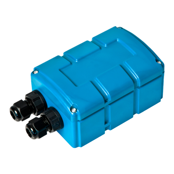
- Page 17 Chapter 4 General specifications 4.5 Overview Front of the myDatalogEASYplus Rear of the myDatalogEASYplus 1 Housing cover 3 Cable screw connection (cable diameter of 5- 10 mm) 2 Antenna connector 4 Pressure compensation Rev. 06...
-
Page 18: Block Diagram
4.5.1 Block diagram Block diagram of the myDatalogEASYplus 4.6 Intended use The portable measurement instrument is used to collect analogue and digital signals. The device can operate without mains power. The measured and recorded data is stored in a non-volatile memory medium. -
Page 19: General Product Information
USB interface. 4.8 Device labelling The specifications in this manual apply exclusively to the device type myDatalogEASYplus . The type plate is located on the right side of the device and includes the following specifications:... - Page 20 If you are using an external charging voltage to charge the accu pack of the myDatalogEASYplus , disconnect this from the device before removing the accu or battery pack. The remaining cables and antenna can then be removed. Store the myDatalogEASYplus and accu or battery pack in the compartments provided in the original packaging.
-
Page 21: Obligation Of The Operator
Chapter 4 General specifications 4.11 Obligation of the operator WARNING: In the EEA (European Economic Area), the national implementation of the framework directive (89/391/EEC) as well as the associated specific directives and from these in particular, the directive (89/655/EEC) about the minimum safety and health requirements for use of work equipment by workers at work, each in their respective version are to be complied with. -
Page 23: Chapter 5 Functional Principle
Functional principle myDatalogEASYplus with integrated managed service SIM chip (including data transmission) 2 myDatanet server to which the data is transferred 3 Client that accesses the interface of the myDatanet server via the web browser 4 Customer-specific server that provides clients with their own interface. - Page 24 Functions and components provided by myDatanet : myDatalogEASYplus The myDatalogEASYplus is a compact portable device for connecting sensors (UI1-4) to the myDatanet server (GPRS). Managed Service Managed Service is the basis for operating your devices and provides you with a wide range of services.
-
Page 25: Internal Processing Of The Measurement Values
Chapter 5 Functional principle 5.1 Internal processing of the measurement values Diagram of the internal processing of the measurement values 1 Filter to compensate for brief signal 7 Determination of the setpoints, (see "Control fluctuations (see "Filter module" on page module"... - Page 26 Note: Additional explanation on universal inputs that are operated in digital or digital LP mode. Measurement channels -> Mode digital Basis Measurement channels - Filter time 800ms >Config. Input signal Input signal at the universal input Input signal after filter Input signal taking the "filter time" into consideration Logic level The input signal at the universal input is analysed once per second.
- Page 27 Chapter 5 Functional principle 5.1.1 Filter module The filter module is designed to compensate for brief fluctuations to the input signal. This module is only available for the 4 universal inputs. The following table specifies the relevant parameters for the module: Configuration section Mode Parameter...
-
Page 28: Scale Module (Inputs)
5.1.3 Scale module (inputs) This module rescales the raw value (e.g. mA) to the required measurement value (e.g. mm). The scale module is only available for the 4 universal inputs. The following table specifies the relevant parameters for the module: Configuration section Mode Parameter... -
Page 29: Decay Module
Chapter 5 Functional principle 5.1.4 Decay module The decay module is designed to summarise several measurement values. The average value over a required time frame or the minimum value within a required time frame can be determined, for example. The decay module is only available for the 4 universal inputs, with the exception of "Cnt.Day"... - Page 30 5.1.5 Hold module With the help of the hold module, it can be determined how to proceed in the event of invalid measurement values. It ensures the last valid measurement value is retained until a new valid measurement value is available or passes the error on after a certain number of invalid measurements.
-
Page 31: Control Module
Chapter 5 Functional principle 5.1.7 Control module The control module determines the setpoints for the outputs. The following table specifies the relevant parameters for the module: Configuration section Mode Parameter Explanation Output channels Ext warmup time Ext warmup Indicates the amount of time that an time output channel is switched on in "Ext warmup time"... -
Page 32: Record Module
5.1.8 Record module The record module records the measurement values. As the record interval and measurement cycle can be selected individually, a record is not completed at the time of every measurement. Depending on the global triggers set by the alarm/trigger module (see "Alarm flags" on page 33 or "Trigger flags"... - Page 33 Chapter 5 Functional principle Configuration section Parameter Explanation Basic settings Record interval Time between measurement data recordings 5.1.8.1 Alarm flags const // Warning MDN_FLG_WARNING = 0b00000001, // Alarm MDN_FLG_ALARM = 0b00000010, // Technical error of low priority MDN_FLG_FAULTLOW = 0b00000100, // Technical error of high priority MDN_FLG_FAULTHIGH = 0b00001000, // Shortfall of the alarm level...
-
Page 34: Setpoint Module
5.1.9 Setpoint module This module uses the setpoints for the outputs entered via the configuration interface of the myDatanet server. The following table specifies the relevant parameters for the module: Configuration section Mode Parameter Explanation Output channels -> Basis Ext warmup time Digital Setpoint... -
Page 35: Scale Module (Outputs)
Chapter 5 Functional principle 5.1.10 Scale module (outputs) This module rescales the setpoint (e.g. mm) into the desired physical size (e.g. frequency) for the output. The following table specifies the relevant parameters for the module: Configuration section Mode Parameter Explanation Output channels Ext warmup time... -
Page 36: Procedure In Case Of Connection Aborts
The internal data memory of the myDatalogEASYplus is designed as a circular buffer with 4 sectors. If the maximum number of data records (25.588 ) is achieved, the sector with the oldest data is deleted fully before new data can be saved in this sector again. This means that the internal data memory at the very least contains the measurement values of the last 19191 cycles, however at most the measurement values of the last 25.588 cycles. -
Page 37: Aloha Transmission Mode
Chapter 5 Functional principle 5.4 ALOHA transmission mode ALOHA transmission mode is a special connection mode whereby the myDatalogEASYplus establishes a connection to the myDatanet server for a period of time configured via the "Basic settings" configuration section (see "Aloha/wakeup duration" in chapter "Basic settings" on page 96). -
Page 38: Automatic Selection Of The Gsm Network
5.5 Automatic selection of the GSM network The GSM network to which the device should register must be selected, as the myDatalogEASYplus is equipped with a SIM chip that provides a mobile connection via a variety of international service providers (see www.microtronics.at/footprint ). This is completed automatically by the device. During this process it is taken into consideration if a connection to a certain GSM network is possible although the use of this GSM network repeatedly causes transmission errors. - Page 39 Chapter 5 Functional principle If there is a GPRS error (see error codes -975 to -993 in chapter "Modem error" on page 128), then an internal counter is increased by 2 . If a transmission was completed without errors, i.e. all of the data was transferred, this internal counter is reduced by 1 .
-
Page 41: Chapter 6 Storage, Delivery And Transport
Check the shipment immediately upon receipt to ensure it is complete and intact. Immediately report any discovered transport damages to the delivering carrier. Also notify Microtronics Engineering GmbHin writing about this without delay. Report any incompleteness of the delivery to the responsible representative or directly to the company headquarters of the manufacturer within two weeks (see "Contact information"... - Page 42 Note: The table above only includes the storage conditions for the two energy sources used most frequently for the myDatalogEASYplus . Please consult the appropriate factsheet for information about the storage conditions of other accu or battery packs. Important note: Remove the accu or battery pack from the myDatalogEASYplus prior to storage.
-
Page 43: Chapter 7 Installation
Comply with existing legal and/or operational directives. Improper handling can cause injuries and/or damage to the devices. The myDatalogEASYplus must not be operated in the field with the lid open. The myDatalogEASYplus is not approved for use in closed channels. -
Page 44: Wall Mounting
For wall mounting the optional "Universal bracket for housing myDatanet 86x126 (206.640)" equipment is required. Step 1 of the wall mounting Step 2 of the wall mounting 1 myDatalogEASYplus 3 Assembly loop (included in the delivery scope of 206.640) 2 Delta PT M3.5x8 Torx 15 (included in the 4 Raised head tapping screw 3.5x32 (included... - Page 45 If you want to use the tapping screws (4) included in the equipment set, first of all insert the supplied wall plugs into each of the four drill holes before screwing the myDatalogEASYplus with the attached assembly loop (3) to the wall (see "Step 2 of the wall mounting" on page 44).
- Page 46 2. Place the assembly loop (3) onto the top edge of the top-hat rail. When turned slightly around the horizontal axis of the myDatalogEASYplus with the assembly loop (3) attached, the assembly loop (3) engages on the top-hat rail (see "Step 2 of the top-hat rail assembly" on page 46).
-
Page 47: Pipe Assembly
86x126 (206.660)" equipment set to the myDatalogEASYplus (see "Step 1 of the pipe assembly " on page 47). 2. Position the myDatalogEASYplus with the attached assembly loop (3) on the pipe and use the supplied cable binders (4) to secure the myDatalogEASYplus (see "Step 2 of the pipe assembly"... -
Page 48: Safety Instructions For The Cabling
Important note: To avoid any damage, always switch off the voltage supply to the device when performing electrical connections. When connections are made to the myDatalogEASYplus , the following warnings and information must be observed, in addition to the warnings and information found in the individual chapters on the installation. -
Page 49: Electrical Installation
Run all data and power cables so that they do not pose a trip hazard and ensure that cables do not have any sharp bends. The myDatalogEASYplus must not be operated in the field with the lid open. The myDatalogEASYplus cannot be operated without an internal power supply... - Page 50 Connection of the sensors and power supply 1 Mounting for the rechargeable battery or 6 Cable screw connection (cable diameter of 5- battery pack 10 mm) 2 Status LED 7 Main terminal block X12 3 Button 8 Supply connector 4 Housing cover 9 Rechargeable battery or battery pack 5 connector X4 for the external temperature 10 Antenna connector...
- Page 51 1. Remove the four screws that secure the housing cover. Now open the myDatalogEASYplus . Important note: In the event of adverse weather conditions including rain or in a location where water can penetrate from above, suitable measures must be implemented to protect the device from penetrating moisture when the housing cover is open.
- Page 52 6. Insert the rechargeable battery or battery pack into the myDatalogEASYplus and secure it with the appropriate mounting. 7. Connect the antenna (see "Connecting the GSM antenna" on page 54). The antenna is not included in the scope of delivery and must be ordered separately.
- Page 53 . Attaching an external voltage will cause damage to the universal input. batt Connection examples: Use of the switchable sensor supply 1 Terminal strips of the myDatalogEASYplus 4 2-wire mA sensor 2 Sensor with open collector output 5 3-wire mA sensor or 3-wire U-sensor 3 Isolated relay contact Note: The "Cnt.Day", "Cnt.Intervl.", "Freq"...
-
Page 54: Connecting The Gsm Antenna
The standard antenna is directly attached to the antenna connector (see "Overview" on page 17) of the myDatalogEASYplus . In the event of a low radio signal strength, you can use the Flat antenna Smart Disc FME-F 2,5m (206.814). -
Page 55: Technical Details About The Universal Inputs
Chapter 7 Installation If the distance between the antenna position and the myDatalogEASYplus is too great, you can use a 5 m Extension cable for antenna FME-F/FME-M 5m (206.805). 1. Ensure that the myDatalogEASYplus is de-energised. 2. If you need an antenna extension, connect it to the antenna first. -
Page 56: Technical Details About The Outputs
7.4.3.3 0 to 10V mode Resolution 8,3mV Load 7.4.3.4 Standard digital modes (PWM, frequency, digital, day counter, impulse counter) General <1,36V High >2,73V Load Measurement 1...99% range 100Hz Minimum impulse length Frequency Measurement 1...1000Hz range Day and Minimum 20ms impulse impulse length counter 7.4.3.5 Low power digital mode (LP digital) -
Page 57: Technical Details Regarding Energy Management
7.4.5 Technical details regarding energy management The device will work until 3,1V, if the myDatalogEASYplus is operated without an external charging voltage (V ). It then switches to energy-saving mode in which only the charge controller is active. If an external charging voltage (V ) is supplied in this mode, the accu pack can be charged up again. - Page 58 also assigned the title "solar", the accu pack is constantly charged (recommended if a solar field is used to charge the accu pack). For all of the other accu pack type settings, the accu pack is always charged to the maximum voltage, after which charging is switched off and only reactivated when (see "Device-specific settings"...
-
Page 59: Chapter 8 Initial Start-Up
8.3 Placing the system into operation Note: It is recommended that the myDatalogEASYplus is first placed into operation in the office before permanently mounting the device at the place of use. In doing so you should set a site for the later operation on the myDataweb server (see "myDatanet Server Manual "... -
Page 60: Testing Communication With The Device
2. Configure the created site according to your requirements (see "Site configuration" on page 65). 3. Link the myDatalogEASYplus with the created site (see "Site" on page 65 or "Creating the site" on page 106 ). 4. Initiate the ALOHA transmission mode (see "ALOHA transmission mode" on page 37) so that the configuration of the site is transferred to the myDatalogEASYplus . - Page 61 Chapter 8 Initial Start-Up 8. Check the incoming data in the ALOHA data window of the myDatanet server, which can be accessed by clicking on the speech bubble with the "Aloha" inscription (see "myDatanet Server Manual " 805002). Particular attention must be paid to the internal"GSM level" and "Battery"...
-
Page 63: Chapter 9 User Interfaces
Chapter 9 User interfaces Chapter 9 User interfaces The configuration of the myDatalogEASYplus is carried out via the web interface on the myDatanet server (see "User interface on the myDatanet-Server" on page 65), which your responsible sales partner will provide to you. - Page 64 Transport lock (GPRS OFF, measurement If the ALOHA transmission mode is OFF) initiated by the button or solenoid switch , the myDatalogEASYplus switches back into "RUN" mode (GPRS ON, measurement ON). Last connection OK Last transmission faulty Try again later Standby (GPRS ON, measurement OFF) see "transport lock"...
-
Page 65: Site Configuration
Chapter 9 User interfaces User action Device response Operation after releasing the button Press briefly for Status LED illuminates Error/status code is displayed (see approx. one "Status LED" on page 63) second Press and hold for Status LED flashes three times and ALOHA transmission mode five seconds then remains on... - Page 66 9.2.1.3 Measurement channels 9.2.1.3.1 Basis Title 1-4 Freely selectable channel title for the universal inputs Title 1Wire Freely selectable channel title for the external temperature sensor Mode Basic settings for the measurement channel Universal Measurement channel deactivated inputs digital Invert Inverts the input signal (Digital digital LP...
- Page 67 Chapter 9 User interfaces Universal 0-20mA Start of the measurement range in the measurement inputs unit 100% End of the measurement range in the measurement unit (analogue modes) Unit String that is used as a measurement unit by all of the server display elements [0-16 characters] Decimal Number of decimal places that are used by all of the...
- Page 68 9.2.1.3.2 Config Universal inputs Digital Filter time Time in [ms] during which the signal must remain (Digital constant to initiate a level change. Used to suppress modes 1/2) brief faults (debouncing). Decay Temporal function in the measurement cycle Decay deactivated Minimum signal length for x seconds with a rising edge down Minimum signal length for x...
- Page 69 Chapter 9 User interfaces Universal inputs Cnt.Day Filter time Time in [ms] during which the signal must remain constant to initiate a level change. Used to suppress (Counter modes) brief faults (debouncing). Reset at Reset time of the day counter Cnt.Intervl.
- Page 70 Note: Additional explanation regarding the difference between "Cnt.Day" and "Cnt.Intervl." Basic setting Record interval 4 min. Recorded value red line Measurement cycle 1 min. Measurement value blue line "Cnt.Intervl." mode: The pulses are added up and reset "Cnt.Day" mode: All of the pulses up to the reset time every time a measurement value is generated.
- Page 71 Chapter 9 User interfaces Universal inputs Freq Filter time Time in [ms] during which the signal must remain constant to initiate a level change. Used to suppress (Frequency mode (1/2) brief faults (debouncing). 1/2) Decay Temporal function in the measurement cycle Decay deactivated The minimum of the last x measurement values is recorded.
- Page 72 Universal inputs Freq Overflow Procedure in the event of measurement range violations (Frequency mode (2/2) Ignore The measurement value is calculated 2/2) beyond the range limits. Silent The measurement value is truncated at the cutoff range limits. Out of If the measurement value is below range 1Hz, the error value "UF"...
- Page 73 Chapter 9 User interfaces Universal inputs Filter time Time in [ms] during which the signal must remain constant to initiate a level change. Used to suppress (PWM mode 1/2) (1/2) brief faults (debouncing). Decay Temporal function in the measurement cycle Decay deactivated The minimum of the last x measurement values is recorded.
- Page 74 Universal inputs Overflow Procedure in the event of measurement range violations (PWM mode 2/2) (2/2) Ignore The measurement value is calculated beyond the range limits. Silent The measurement value is truncated at the cutoff range limits. Out of If the measurement value is below range 1%, the error value "UF"...
- Page 75 Chapter 9 User interfaces Universal inputs 0-20mA Filter time Time in [ms] during which the analogue signal is averaged for signal smoothing. Used to suppress (0-20mA mode (1/2) signal noise (also see "Output channels" on page 88). 1/2) Decay Temporal function in the measurement cycle Decay deactivated The minimum of the last x measurement values is recorded.
- Page 76 Universal inputs 0-20mA Overflow Procedure in the event of measurement range violations (0-20mA mode (2/2) Ignore The measurement value is calculated 2/2) beyond the range limits. Silent The measurement value is truncated at the cutoff range limits. Out of If the measurement value is above range 20.1 mA, the error value "SC"...
- Page 77 Chapter 9 User interfaces Universal inputs 4-20mA Filter time Time in [ms] during which the analogue signal is averaged for signal smoothing. Used to suppress (4-20mA mode (1/2) signal noise (also see "Output channels" on page 88). 1/2) Decay Temporal function in the measurement cycle Decay deactivated The minimum of the last x measurement values is recorded.
- Page 78 Universal inputs 4-20mA Overflow Procedure in the event of measurement range violations (4-20mA mode (2/2) Ignore The measurement value is calculated 2/2) beyond the range limits. Silent The measurement value is truncated at the cutoff range limits. Out of The error value "OL" (open loop) is range issued, if the measurement value is below 3.9mA.
- Page 79 Chapter 9 User interfaces Universal inputs 0-2V Filter time Time in [ms] during which the analogue signal is averaged for signal smoothing. Used to suppress (0-2V mode 1/2) (1/2) signal noise (also see "Output channels" on page 88). Decay Temporal function in the measurement cycle Decay deactivated The minimum of the last x measurement values is recorded.
- Page 80 Universal inputs 0-2V Overflow Procedure in the event of measurement range violations (0-2V mode 2/2) (2/2) Ignore The measurement value is calculated beyond the range limits. Silent The measurement value is truncated at the cutoff range limits. Out of If the measurement value is above 2.01V, range the error value "OF"...
- Page 81 Chapter 9 User interfaces Universal inputs 0-10V Filter time Time in [ms] during which the analogue signal is averaged for signal smoothing. Used to suppress (0-10V mode 1/2) (1/2) signal noise (also see "Output channels" on page 88). Decay Temporal function in the measurement cycle Decay deactivated The minimum of the last x measurement values is recorded.
- Page 82 Universal inputs 0-10V Overflow Procedure in the event of measurement range violations (0-10V mode 2/2) (2/2) Ignore The measurement value is calculated beyond the range limits. Silent The measurement value is truncated at the cutoff range limits. Out of If the measurement value is above 10.05 V, range the error value "OF"...
- Page 83 Chapter 9 User interfaces 9.2.1.3.3 Alarms "Digital" or "digital A "high" at the universal input triggers a "warning". LP" mode A "high" at the universal input triggers an "alarm". A "high" at the universal input triggers a "fault warning". A "high" at the universal input triggers a "fault alarm". All other modes Warning Value low A warning is triggered, if the measurement value...
- Page 84 "Digital" Event Start measurement cycle immediately or "digital trigger Initiate transmission LP" mode Edges Selection of the edge at which the trigger should be initiated rising Rising edge initiates the trigger. falling Falling edge initiates the trigger. both Both edges initiate the trigger. Level Fastrecording (record interval = record interval / factor) trigger...
- Page 85 Chapter 9 User interfaces Mode Possible calculation modes for the calculated channels Calculated channel deactivated Table Unit String that is used as a measurement unit by all of the server display elements [0-16 characters] Decimal Number of decimal places that are used by all of the server display places elements Digital...
- Page 86 9.2.1.4.2 Calculation Calculated channel deactivated Table Source Selection of the channel from which the input data is used Opens the screen for entering the values table (the table rows are interpolated linearly, values outside of the defined table are extrapolated linearly.) Digital Source...
- Page 87 Chapter 9 User interfaces Note: Additional explanation: Delta mode Assumption: The source channel contains the counter reading of an infinite counter in m . The calculated channel 1 should contain the flow rate in m /s and calculated channel 2 should contain the flow rate in l/h. Required configuration Parameter Value channel 1...
- Page 88 9.2.1.4.3 Alarms Note: The evaluation of the alarm thresholds for calculated channels can only occur if the device has transferred the measurement data to the myDatanet server. Alarm low An alarm is triggered, if the measurement value drops to or below this value. Alarm high An alarm is triggered, if the measurement value meets or exceeds this value.
- Page 89 Chapter 9 User interfaces Mode Basic setting for the output channel Output channel deactivated Ext warmup The output channel is switched on "Ext warmup time" seconds prior to the time measurement. If the value is "0", the output channel is not switched on at all. Digital Invert Inverts the level issued on the device(see "Additional...
- Page 90 Note: Additional explanation on "Digital" mode Invert Setpoint Output on the device Off (low) On (high) On (high) Off (low) Note: Example to explain the burst interval in conjunction with the ext. warmup time (ext. warmup time < measurement cycle): Basic setting Record interval 5min.
- Page 91 Chapter 9 User interfaces Note: Example to explain the burst interval in conjunction with the ext. warmup time (ext. warmup time > measurement cycle): Basic setting Record interval 5min. Burst interval 75 sec. Measurement cycle 15 sec. Output channels Ext warmup time 30 sec.
- Page 92 Note: Example to explain the filter time in conjunction with the ext. warmup time Basic setting Record interval 5min. Measurement cycle 1min. Output channels Ext warmup time 1sec. Measurement channels - Filter time 500ms >Config. Output on the device Sensor supply Explanation: The sensor supply is always activated 1 sec before expiry of the measurement cycle.
- Page 93 Chapter 9 User interfaces 9.2.1.6 Internal channels 9.2.1.6.1 Basis Voltage title Freely selectable channel title for V (external charging voltage) Unit String that is used as a measurement unit by all of the server display elements [0-16 characters] Battery title Freely selectable channel title for the internal battery or accu voltage Unit String that is used as a measurement unit by all of the server display elements [0-16 characters]...
- Page 94 9.2.1.6.3 Trigger Fastrecording (record interval = record interval / factor) Slow recording (record interval = record interval * factor) Switch on recording Switch off recording Initiate transmission Activate online mode The reduced transmission cycle should be used. Level Levels for initiating the trigger. The hysteresis from the "Alarm" tab is used to determine the level to reset the trigger.
- Page 95 Chapter 9 User interfaces 9.2.1.7 Alarm settings Acknowledgement Standard The global server setting is used to determine whether alarms must be acknowledged automatically or manually. (see "myDatanet Server Manual " 805002). Automatic Alarms are acknowledged automatically as soon as all of the messages have been sent.
- Page 96 9.2.1.8 Basic settings Connection type Interval The device connects in the transmission cycle. Interval & wakeup The device connects to the server in the transmission cycle and can be placed into ALOHA transmission mode via the server. online The device does not separate the connection and continuously transmits the measurement data.
- Page 97 Chapter 9 User interfaces Default report Selection of the report that is loaded by clicking on the device link in the maps The default graphic is loaded. "Name of a The selected report is loaded. report" Report template Selection of whether the default graphic or a report template to display the data is used when clicking on the symbol to display the measurement data located in the site/application list (not assigned)
-
Page 98: Device Configuration
Note: Additional explanation about the connection types Connection type Energy consumption Data volumes Response time online Interval & wakeup Interval 9.2.1.9 FTP export settings Note: This configuration section is only visible if the "FTP Agent Extended" licence for the myDatanet-Server has been enabled. - Page 99 Chapter 9 User interfaces Telephone Telephone number of the SIM card. The control SMS messages (e.g. wakeup) are number sent to this number. Format: +43555837465 Instrument Additional information regarding the instrument class (for internal use) flags Firmware Current software version installed on the measurement controller version Modem Current software version installed on the modem controller...
- Page 100 Firmware type Released Only firmware versions that have successfully undergone internal and field testing are installed (this practically eliminates malfunctions). Release candidate Only firmware versions that have successfully undergone internal testing are installed (malfunctions cannot be excluded). Beta release Even firmware versions that have not successfully undergone all of the internal tests are installed (malfunctions may occur).
- Page 101 Chapter 9 User interfaces 9.2.2.4 GPRS SIM tariff Selected SIM tariff Rev. 06...
-
Page 103: Chapter 10 Mydatanet Server
Chapter 10 myDatanet server Chapter 10 myDatanet server Note: All of the screenshots show version 42.2 of the myDatanet server using the standard colour scheme. Newer versions may include minor changes to the appearance of the server. 10.1 Overview Overview of the myDatanet server 1 Freely selectable logo 5 Opens the screen to input the global settings for the server... - Page 104 10.2 "Customer" area Overview of the "Customer" area 1 Current "Overview map" on which the sites can be placed 2 Adds a new customer 3 Opens the input screen for configuring the customer 4 Deletes the customer 5 Comment that can be entered in the configuration of the customer 6 If a default report was defined, the default report is accessed by clicking on the name of the customer.
- Page 105 Chapter 10 myDatanet server 10.3 "Site" area at customer level Overview of the "Sites" area at customer level 1 Symbol via which an image file can be loaded on to the server as a "Map" To remove the "Map" again, open the upload dialogue again and click on "Submit" without selecting an image file beforehand.
-
Page 106: Map View
10.3.1 Reports The reports provide a variety of options to display graphs of the data on the web interface of the myDatanetserver or to download the data from the myDatanet server. Detailed instructions on creating and handling the reports is provided in myDatanet Server Manual (805002). 10.3.2 Map view The map view provides an overview of the geographic position of the sites. - Page 107 3. Click on the "Sites / Applications" menu item of the myDatanet server to call up the list of available application templates and sites. Create a new "myDatalogEASYplus " type site or a site using an application template that is compatible with the "myDatalogEASYplus " site type.
- Page 108 1. Log in via the web interface on the myDatanet server. You will receive the web address from your responsible sales partner. Login form of the myDatanet server 2. Click on the "Pool and Aloha" menu item of the myDatanet server to access the list of devices that are in ALOHA transmission mode.
- Page 109 Chapter 10 myDatanet server 4. Use the filter to find the required device in the list of measurement instruments. Click on the symbol to open the dialogue to select the customer (see "Assigning a device to the customer" on page 108) and assign the device to the selected customer. Rev.
-
Page 111: Chapter 11 Xml Interface
Chapter 11 XML interface Chapter 11 XML interface Important note: The relevant licences are required on the myDatanet server to use the XML interface. If the licence is not available for the XML export, the following message is displayed for every request: " ". -
Page 113: Chapter 12 Maintenance
Check all of the connections for leaks or corrosion on a regular basis. Check all of the cables for mechanical damage at regular intervals. Clean the myDatalogEASYplus with a soft, moist cloth. Use a mild cleaning agent, if necessary. 12.2 Replacing the rechargeable battery or battery pack... - Page 114 Replacing the rechargeable battery or battery pack 1 Mounting for the rechargeable battery or bat- 6 Cable screw connection (cable diameter of 5- tery pack 10 mm) 2 Status LED 7 Main terminal block X12 3 Button 8 Supply connector 4 Housing cover 9 Rechargeable battery or battery pack 5 connector X4 for the external temperature 10 Antenna connector...
- Page 115 2. If you are using an external charging supply to charge the rechargeable battery pack of the myDatalogEASYplus , disconnect this from the device before opening the housing cover. Important note: The charge controller of the myDatalogEASYplus can be damaged or...
- Page 116 The accu packs are delivered charged. If you use an external charging voltage (V ) during operation, the accu pack is constantly charged by the charge controller integrated in the myDatalogEASYplus . If no external charging voltage (V ) is available during operation, it is recommended to recharge the accu pack prior to first use for reasons of operational safety.
-
Page 117: Accu Or Battery Pack
Chapter 12 Maintenance Note: Accu packs are wear parts that lose capacity over time. The capacity is also reduced at high or low ambient temperatures and under intensive use. Important note: The use of spare and wear parts (e.g. accu or battery packs, etc.) which are not approved by the manufacturer shall void the warranty. -
Page 119: Chapter 13 Removal/Disposal
Dispose of the device in accordance with the locally valid environmental regulations for electronic products. Rechargeable batteries and/or battery packs may not remain in the myDatalogEASYplus after dis- charging. Ensure that the used rechargeable batteries and/or battery packs are disposed of in an environmentally proper way. -
Page 121: Chapter 14 Troubleshooting And Repair
Communication problems Evaluate the blink code of the status LED (see "Status LED" on page 63). Load the device log from the myDatalogEASYplus or the myDataweb server and use myDatanetDeviceConfig for the evaluation (see "Evaluating the device log" on page 131). - Page 122 Problem Cause/solution Isolated switch contact is Disruption to the voltage that is conducted via the isolated not working switch contact. The site settings were overwritten by a server-PLC. The value set via the input The site settings were overwritten by a server-PLC. screen on the myDataweb server is not issued at the output channel.
-
Page 123: Log Entries And Error Codes
Chapter 14 Troubleshooting and repair 14.2 Log entries and error codes Log entry Parameter Description Code Plain text Code Plain text 1000 POWER ON System start completed > 0 Internal system error Restart due to internal system error. There may be a hardware problem if the "POWER ON"... - Page 124 Log entry Parameter Description Code Plain text Code Plain text 1034 CONTROLLER_ Update of the firmware for the measurement UPDATE controller was completed successfully This entry is always duplicated in the device log. In the first entry, the parameter specifies the major version number (e.g.
- Page 125 Chapter 14 Troubleshooting and repair Log entry Parameter Description Code Plain text Code Plain text 1212 ERROR MODEM Indicates a faulty connection. The parameter IRREGULAR OFF includes a counter that indicates how many consecutive connections have not worked. 1224 MODEM SIM RESET --- The GPRS modem has been restarted to reinitialise the SIM chip again.
- Page 126 Check the connection between the device and sensor. HOLD Standby (GPRS ON, measurement OFF) If ALOHA transmission mode is initiated on the device, the myDatalogEASYplus switches back into "RUN" mode (GPRS ON, measurement ON). TRANSPORT Transport lock (GPRS OFF, measurement OFF) see "Standby"...
- Page 127 Chapter 14 Troubleshooting and repair Log entry Parameter Description Code Plain text Code Plain text 1600 STATE GPRS ERROR No GPRS connection (2/2) (2/2) Try to improve the position of the antenna. IP ERROR No myDatanet server available Check whether port 51241 is enabled on the myDatanet server.
- Page 128 Try again later BEARER NO -992 --- No answer ANSWER Try again later Check whether the device is in the coverage area (www.microtronics.at/footprint). BEARER NO -991 --- No carrier CARRIER Try again later Check whether the device is in the coverage area (www.microtronics.at/footprint).
- Page 129 1200 BEARER GPRS STOP -976 --- Invalid handling BAD HDL Internal error BEARER GPRS STOP -975 --- Internal error UNKNOWN 1200 NETLOCK FAILURE -970 --- Error when selecting the network Check whether the device is in the coverage area (www.microtronics.at/footprint). Rev. 06...
- Page 130 Try to improve the position of the antenna. Check whether the device is in the coverage area (www.microtronics.at/footprint). TCP channel error (1/2) 1200 CHANNEL ABORTED -965 --- An attempt is being made to write to/read a TCP client that is no longer available.
-
Page 131: Evaluating The Device Log
The optional equipment optional SIM/USB card-slot (206.404) is required to read the log entries directly from the myDatalogEASYplus using the myDatanetDeviceConfig. With this equipment, all of the log entries stored in the device, including those that have not yet been transmitted to the myDataweb server can be read. - Page 132 A more detailed description about the evaluation of the device log using myDatanetDeviceConfig is included in the manual for the myDatanetDeviceConfig ("myDatanetDeviceConfig Manual" 805004). Rev. 06...
-
Page 133: Chapter 15 Spare Parts And Accessories
Chapter 15 Spare parts and accessories Chapter 15 Spare parts and accessories 15.1 Internal expansions Note: The following components are order options. They cannot be ordered separately or installed by the customer. Description Quantity Order no. optional SIM/USB card-slot 206.404 12VDC sensor supply 206.750 24VDC sensor supply... -
Page 134: Other Accessories
15.4 Rechargeable battery packs and battery packs Description Quantity Order no. Battery packs BP434R Battery (-20...+50°C operating temperature) 206.718 Rechargeable battery packs AP413D rechargeable battery (Li-Ion ; 13,2Ah; -20...+60°C operating 206.721 temperature,0...+40°C charging temperature)) AP413D+ rechargeable battery (Li-Ion ; 13,6Ah; -20...+60°C operating 206.722 temperature, -20...+60°C charging temperature) 15.5 Charging devices and power supply units... -
Page 135: Chapter 16 Document History
Chapter 16 Document history Chapter 16 Document history Rev. Date Changes 06 10.09.2015 Chapter "ALOHA transmission mode" on page 37 Information added indicating that the GSM network is selected again when ALOHA transmission mode is initiated. Chapter "Connecting the GSM antenna" on page 54 Information on correctly tightening the antenna supplemented Chapter "Testing communication with the device"... -
Page 137: Chapter 17 Glossary
The manufacturer's devices are equipped with subscriber identity modules (SIM) ex-works for the purpose of mobile data transmission. The footprint describes the countries and regions, in which a mobile connection is available (see www.microtronics.at/footprint). NaN value The myDatanet uses special encoding to display different error statuses in the measurement values, for example. -
Page 139: Chapter 18 Contact Information
Chapter 18 Contact information Chapter 18 Contact information Support & Service: Microtronics Engineering GmbH Hauptstrasse 7 3244 Ruprechtshofen Austria, Europe Tel. +43 (0)2756 7718023 support@microtronics.at www.microtronics.at Microtronics Engineering GmbH Microtronics Engineering GmbH (Headquarter) Windthorststrasse 5 Hauptstrasse 7 63179 Obertshausen 3244 Ruprechtshofen...
Need help?
Do you have a question about the myDatalogEASYplus and is the answer not in the manual?
Questions and answers