
Related Manuals for Microtronics myDatalogEASY V3


Summary of Contents for Microtronics myDatalogEASY V3
- Page 1 User manual myDatalogEASY V3 Cover Valid from: Firmware version: 01v015 Server version: 49v011 Hardware version: 4.0 300574 | Rev.05...
- Page 3 Chapter 1 Table of contents Chapter 1 Table of contents Cover Chapter 1 Table of contents Chapter 2 Declaration of conformity Chapter 3 Technical data Chapter 4 General specifications 4.1 Translation 4.2 Copyright 4.3 General descriptive names 4.4 Safety instructions 4.4.1 Use of the hazard warnings 4.4.2 General safety instructions 4.4.3 Safety and preventative measures for handling GSM/GPRS modems...
- Page 4 5.4.1 Connection abort in "online" mode 5.4.2 Connection abort during a Device Logic download 5.5 Automatic selection of the GSM network 5.6 Determining the GSM/UMTS/LTE signal strength 5.7 Determining the GSM position data 5.8 Error handling 5.9 Registration memory blocks 5.9.1 REG_APP_OTP 5.10 File transfer 5.11 Meaning of the SIM state...
- Page 5 Chapter 1 Table of contents 7.6.3.1 0/4 to 20mA mode 7.6.3.2 0 to 2V mode 7.6.3.3 0 to 10V mode 7.6.3.4 Standard digital modes (PWM, frequency, digital, counter) 7.6.4 Technical details about the PT100/1000 interface 7.6.5 Technical details about the RS485 interface 7.6.6 Technical details about the RS232 interface 7.6.7 Technical details about the USB interface 7.6.8 Technical details about the outputs...
- Page 6 9.2 User interface on the myDatanet server 9.2.1 Site configuration 9.2.1.1 Site 9.2.1.2 Comments 9.2.1.3 Control 9.2.1.4 Configuration 0 - Configuration 9 9.2.1.5 Alarm settings 9.2.1.6 Basic settings 9.2.1.7 FTP export settings 9.2.2 Device configuration 9.2.2.1 Comments 9.2.2.2 Measurement instrument 9.2.2.3 GPRS Chapter 10 DeviceConfig 10.1 General...
- Page 7 Chapter 1 Table of contents 11.4 Recommended procedure 11.4.1 Creating the site Chapter 12 rapidM2M Studio 12.1 General 12.2 Prerequisites 12.3 Project dashboard 12.4 CODEbed 12.5 TESTbed Chapter 13 Device Logic (Pawn) 13.1 General 13.1.1 Direct entry of a device logic 13.1.2 Uploading a binary file 13.1.3 Using the CODEbed of the web-based development environment rapidM2M Studio 13.2 rapidM2M Device API...
- Page 8 13.2.6.2 Callback functions 13.2.6.3 Functions 13.2.7 Registry 13.2.7.1 Constants 13.2.7.2 Callback functions 13.2.7.3 Functions 13.2.8 Position 13.2.8.1 Arrays with symbolic indices 13.2.8.2 Constants 13.2.8.3 Functions 13.2.9 Math 13.2.10 Char & String 13.2.11 CRC & hash 13.2.11.1 Arrays with symbolic indices 13.2.11.2 Functions 13.2.12 Various 13.2.12.1 Arrays with symbolic indices...
- Page 9 Chapter 1 Table of contents 13.2.17.2 Functions 13.2.18 Outputs 13.2.18.1 Constants 13.2.18.2 Functions 13.2.19 LED 13.2.19.1 Constants 13.2.19.2 Functions 13.2.20 Solenoid switch 13.2.20.1 Constants 13.2.20.2 Callback Funktionen 13.2.20.3 Functions 13.2.21 Power management 13.2.21.1 Arrays with symbolic indices 13.2.21.2 Constants 13.2.21.3 Callback functions 13.2.21.4 Functions 13.3 Device Logic error codes 13.4 Syntax...
- Page 10 13.4.2.6 Floating point values 13.4.3 Constant variables 13.4.4 Array variables 13.4.4.1 One-dimensional arrays 13.4.4.2 Initialisation 13.4.4.3 Progressive initialisation for arrays 13.4.4.4 Multi-dimensional arrays 13.4.4.5 Arrays and the "sizeof" operator 13.4.5 Operators and expressions 13.4.5.1 Notational conventions 13.4.5.2 Expressions 13.4.5.3 Arithmetic 13.4.5.4 Bit manipulation 13.4.5.5 Assignment 13.4.5.6 Comparative operators...
- Page 11 Chapter 1 Table of contents 13.4.6.15 While (expression) statement 13.4.7 Functions 13.4.7.1 Function arguments ("call-by-value" versus "call-by-reference") 13.4.7.2 Named parameters versus fixed parameters 13.4.7.3 Standard values of function arguments 13.5 Differences to C Chapter 14 Data Descriptor 14.1 Data structure 14.1.1 Division of a structured measurement data channel into individual data fields 14.1.2 Division of a configuration memory block into individual data fields 14.1.3 Division of the aloha data into individual data fields...
- Page 12 19.2 Assembly sets 19.3 Antennas 19.4 Power supply units 19.5 Charging devices and power supply units 19.6 Sensors 19.7 Other accessories Chapter 20 Document history Chapter 21 Glossary Chapter 22 Contact information Rev. 05...
- Page 13 Chapter 2 Declaration of conformity Chapter 2 Declaration of conformity Rev. 05...
- Page 15 Chapter 3 Technical data Chapter 3 Technical data Voltage supply Rechargeable battery: PSU413D+ AP : 13,6Ah, Li-Ion , integrated overvoltage protection PSU413D AP : 13,2Ah, Li-Ion , integrated overvoltage protection Battery: PSU713 BP : 13Ah Direct power supply: PSU DC : DC protective circuit PSU DC+ : 900mAh, Li-Po , DC protective circuit PSU AC : 900mAh, Li-Po , 230VAC power supply unit Additional information is provided in "Technical details about the energy supply"...
- Page 16 Universal inputs 4 x analogue or digital Modes: 0/4...20mA: Resolution 6,3µA, max. 23,96mA, load 96Ω 0...2V: Resolution 610µV, max. 2,5V, load 10k086 0...10V: Resolution 7,97mV, max. 32V, load 4k7 PWM: 1...99%, max. 100Hz, min. pulse length 1ms, load 10k086 Frequency: 1...1000Hz, 10k086 Digital: max.
- Page 17 Chapter 3 Technical data Outputs 2 x switchable 3,3V supply (max. 180mA ) 1 x switchable and adjustable sensor supply: The device logic can be used to vary the output voltage in the range of 5...24V . 5V : 4,75V at I = 50mA nominal : 11,7V at I...
- Page 18 Registration Flash: 4 blocks each with 1kB and pre-defined purposes for storing device-specific memory data RAM: 1 optional block with maximum 1kB for storing application-specific data Additional information is provided in "Registration memory blocks" on page 36. Memory for the 256kB (uncompressed size) PAWN binary Additional information is provided in "Memory organisation"...
- Page 19 Chapter 4 General specifications Chapter 4 General specifications The information in this manual has been compiled with great care and to the best of our knowledge. The manufacturer, however, assumes no liability for any incorrect specifications that may be provided in this manual.
- Page 20 Important note: The manufacturer's products that are designed for use outdoors include extensive protection against penetrating moisture and dust. If these products are connected to the power supply or sensors by cables with connectors rather than permanently installed cables, the susceptibility of the connector and socket to moisture and dust penetration is significantly higher.
- Page 21 Chapter 4 General specifications 4.4.3 Safety and preventative measures for handling GSM/GPRS modems The following safety and preventative measures must be observed during all phases of installation, operation, maintenance or repair of a GSM/GPRS modem. The manufacturer is not liable if the customer disregards these preventative measures.
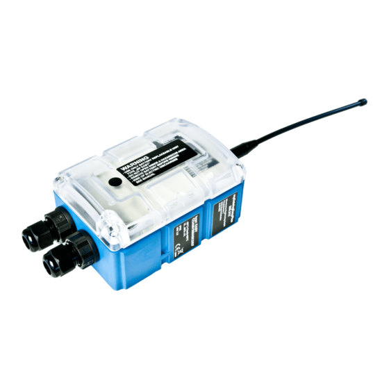
- Page 22 4.5 Overview Note: As the myDatalogEASY V3 is split into several components when delivered, it must be assembled before use (see "Assembling the myDatalogEASY V3 " on page 47). Front of the myDatalogEASY V3 Rear of the myDatalogEASY V3 (view of a device after assembly) (view of a device after assembly) 1 Antenna connector 3 Cable screw connection (cable diameter of 5-...
- Page 23 Chapter 4 General specifications 4.5.1 Block diagram Block diagram of the myDatalogEASY V3 It is a DC/DC converter with controllable output current. A power supply unit (e.g. PSU413D+ AP ) that is equipped with a rechargeable battery can thus be charged via the V in-/output.
- Page 24 A Managed Service contract with Microtronics Engineering GmbH is required for use of the mobile data transmission (see www.microtronics.com/managedservice). This includes the provisioning of the mobile communications connection via the network of the service provider included in the above-mentioned list.
- Page 25 Chapter 4 General specifications rapidM2M Store installation of the device logic is performed via the mobile network connection in the course of connecting the site with the myDatalogEASY V3 . The device logic enables access to the serial interfaces (RS232 and RS485 ) thus providing the customer with the option to connect to almost all of the devices and sensors that are compatible with these interfaces and to implement the corresponding communication protocols.
- Page 26 Type plates myDatalogEASY V3 Note: This symbol indicates the country list profile (see www.microtronics.com/footprint) of the SIM chip installed in the device. Note: These operating instructions are part of the device and must be available to the user at all times. The safety instructions contained therein must be observed.
- Page 27 For safety and warranty reasons, all internal work on the instruments beyond from that involved in normal installation and connection, must be carried out only by qualified Microtronics personnel or persons or companies authorised by Microtronics .
- Page 28 In addition, the operator must comply with the local legal requirements for the safety of the personnel (accident prevention measures), the safety of the equipment (protective equipment and maintenance), the product disposal (waste disposal law), the material disposal (waste disposal law), the cleaning (cleaning agents and disposal) and the environmental protection amendments.
- Page 29 Chapter 5 Functional principle Chapter 5 Functional principle In the graphic below, all of the components that are part of the myDatanet are illustrated in grey. All of the other components must be provided/created by the customer. Functional principle 1 myDatalogEASY V3 with integrated managed service SIM chip (including data transmission) 2 Application created by the customer (Device Logic) that collects and records the data (see "Device Logic (Pawn)"...
- Page 30 Functions and components provided by myDatanet : myDatalogEASY V3 Programmable (see "Device Logic (Pawn)" on page 117), portable device with integrated memory and standardised industrial interfaces (UI1-4, PT100/1000, RS232, RS485, isolated switch contact) to connect sensors and actuators to the myDatanet server (2G/3G) Managed Service Managed Service is the basis for operating the devices and provides a wide range of services.
- Page 31 Chapter 5 Functional principle 5.1 Recommended procedure 5.1.1 Development of M2M/IoT application It is recommended to start with the definition of the Data Descriptor (see "Data Descriptor " on page 235) when developing a M2M/IoT application. It specifies the various data structures (measurement data, configurations, etc.) that are valid for the Device Logic as well as the myDatanet server.
- Page 32 Note: Additional explanation regarding the functionality of the circular buffer Data memory after the first data is recorded: Data memory once 3MB has been recorded Data memory if further data is recorded once 3MB has already been recorded Note: Additional explanation on calculating the data volume to be saved: To provide a clear and simple overview, the following example assumes that the sectors can only record two complete data records.
- Page 33 Chapter 5 Functional principle 5.3 Memory organisation Organisation of the myDatalogEASY V3 memory This memory block is only available if it was initialised via the "rM2M_RegInit()" function. The size of the PAWN binary must not exceed 256kB for the transmission to the myDatalogEASY V3 . If necessary, the data area of the PAWN binary can be compressed using a compiler instruction (#pragma amxcompress <0-3>).
- Page 34 5.4 Procedure in case of connection aborts If the connection is terminated, another attempt to establish a connection is made after 2min. for all connections, except for "online" mode. The connection is attempted up to 2 times. Connection could be established during first retry. Connection could not be established despite 2 retries.
- Page 35 The GSM network to which the device should register must be selected, as the myDatalogEASY V3 is equipped with a SIM chip that provides a mobile connection via a variety of international service providers (see www.microtronics.com/footprint ). This is completed automatically by the device. 5.6 Determining the GSM/UMTS/LTE signal strength The internal update rate of the measurement value for the GSM/UMTS/LTE signal strength is dependent on the type of connection selected via the "rM2M_TxSetMode()"...
- Page 36 5.8 Error handling The following transmission mechanisms have been integrated in the firmware to ensure that problems with the Device Logic can be diagnosed and resolved remotely. In the event that there is no Device Logic, a connection to the myDatanet server is established every 24h . This backup interval is set to 1h if an existing Device Logic has been deactivated due to an error being detected by the system.
- Page 37 Chapter 5 Functional principle The "rM2M_RegGetString()", "rM2M_RegGetValue()", "rM2M_RegSetString()", "rM2M_RegSetValue()", "rM2M_RegDelValue()" and "rM2M_RegDelKey()" functions are available for accessing the registration memory blocks. 5.9.1 REG_APP_OTP By saving the "Product Identity Profile" (PIP) in this registration memory block, the functions described in the following can be initiated on the myDatanet server.
- Page 38 Upon receipt of a file transfer command, a session is started that is automatically terminated after 15sec. if the Device Logic is not handling the command correctly. Sessions can only be active one after another to prevent any conflicts. 5.11 Meaning of the SIM state The device receives information about the permissible use of the SIM chip from the myDatanet server.
- Page 39 Chapter 5 Functional principle State diagram of the SIM states 5.12 Using the external SIM slot Important note: The chargeable "Activation code VPN SIM (300539)" feature must be released to be able to use the external SIM slot. The following two conditions must be met to activate communication via the external SIM card: The SIM card must be inserted in the external SIM slot (see "Inserting/replacing the SIM card"...
- Page 40 The following table specifies under which conditions the external SIM card or internal SIM chip is used. The parameters are checked each time the modem is activated."---" indicates a state where it is not possible to establish a connection. External SIM slot External SIM card Correct APN setting SIM used...
- Page 41 Chapter 5 Functional principle Connection could be established during first retry. Connection could not be established despite 2 retries. EXTSIM An external SIM card was detected following activation of the modem. Note: To ensure that a connection can be established via the external SIM card, as previously mentioned, the valid APN settings must be saved in the myDatalogEASY V3 and the chargeable "Activation code VPN SIM (300539)"...
- Page 43 Check the shipment immediately upon receipt to ensure it is complete and intact. Immediately report any discovered transport damages to the delivering carrier. Also notify Microtronics Engineering GmbHin writing about this without delay. Report any incompleteness of the delivery to the responsible representative or directly to the company headquarters of the manufacturer within two weeks (see "Contact information"...
- Page 44 6.3 Storage The following storage conditions must be observed: myDatalogEASY V3 Storage temperature -30...+85°C Humidity 15...90%rH PSU713 BP Operating temperature -20...+50°C Storage temperature +20...+25°C (300526) PSU413D+ AP Operating temperature -20...+60°C Charging temperature -20...+60°C (300524) Storage temperature 0... +30°C PSU413D AP Operating temperature -20...+60°C Charging temperature 0...+40°C...
- Page 45 Chapter 6 Storage, delivery and transport The following parties must observe these guidelines: Shipping and packaging company Haulage contractors Air carriers and ground handling service providers (only if the IATA guideline is applied) Security personnel (particularly if the IATA guideline is applied) When it comes to transporting hazardous goods, the most important tasks of the shipping and packaging company are: Classification / identification...
- Page 46 Support & Service Centre (see "Contact information" on page 277). The return shipment of the myDatalogEASY V3 must occur in the original packaging and with freight and insurance paid to Microtronics Engineering GmbH (see "Contact information" on page 277). Insufficiently cleared return shipments will otherwise not be accepted! Rev.
- Page 47 Chapter 7 Installation Chapter 7 Installation Important note: To prevent any damage to the device, the work described in this section of the instructions must only be performed by qualified personnel. 7.1 Dimensions Dimensions: width and height Dimensions: depth (view of a device after assembly) (view of a device after assembly) 7.2 Assembling the myDatalogEASY V3 Important note:...
- Page 48 The myDatalogEASY V3 is split into several components when delivered and must therefore be assembled before use. Components of the myDatalogEASY V3 1 Connector plug (2x 2-pin, 2x 3-pin, 1x 6-pin) 4 myDatalogEASY V3 base unit 2 Power supply unit (not included in scope of 5 4x Delta PT M3.5x25 Torx 15 delivery) 3 2x cable screw connections (cable diameter of 5-...
- Page 49 Chapter 7 Installation 3. Turn the locking nut of the cable screw connection clockwise (left-hand thread) to the stop to increase the distance between the locking nut and engagement hook and thus make it easier to insert the cable screw connection into the hole in the myDatalogEASY V3 base unit. The engagement hook is not symmetrical.
- Page 50 4. First of all thread the connection cables of your sensors, actuators and, if necessary, the supply or charging voltage through one of the cable screw connections in accordance with the following figure, and then through one of the holes in the myDatalogEASY V3 base unit. Then connect the cables to the connector plugs as described in chapter "Connecting the sensors, actuators and power supply"...
- Page 51 Chapter 7 Installation 6. Tighten the locking nut by turning it clockwise (left-hand thread). Important note: Ensure that the seal is clean and intact before tightening. Remove any impurities and/or dirt. The manufacturer shall not be liable for any damage to the device caused by leaky or faulty seals.
- Page 52 11. Close the housing cover. The best option is to tighten the four screws crosswise (torque 0,5Nm; At the first screw 0,7Nm because the threads have to be shaped into the base part first.) so that the housing cover is positioned evenly. Important note: Ensure that the seals are clean and intact before closing the housing cover.
- Page 53 Chapter 7 Installation 7.3 Inserting/replacing the SIM card Note: The chargeable feature "Activation code VPN SIM (300539)" must be released to be able to use the SIM slot. Opening the myDatalogEASY V3 1 Delta PT M3.5x25 Torx 15Hexagon socket screw 3 Housing cover M6x30 2 Power supply unit 4 Strap to remove the power supply unit...
- Page 54 3. Remove the SIM slot cover. Opening the SIM slot cover 1 SIM slot cover 4. Insert the SIM as illustrated in Figure B on the circuit board of the myDatalogEASY V3 . Figure on the circuit board of the myDatalogEASY V3 The following step is only necessary if you want to test the connection to the myDatanet server afterwards.
- Page 55 Chapter 7 Installation 9. Check that the housing cover is positioned correctly on all sides and that no foreign materials have been trapped between the housing and housing cover. Important note: The manufacturer is not liable for any damage that is caused by housing covers that are not closed correctly.
- Page 56 7.4.1 Wall mounting For wall mounting the optional "Universal bracket for housing myDatanet 86x126 (206.640)" equipment is required. Step 1 of the wall mounting Step 2 of the wall mounting 1 myDatalogEASY V3 3 Assembly loop (included in the delivery scope of 206.640) 2 Delta PT M3.5x8 Torx 15 (included in the delivery 4 Raised head tapping screw 3.5x32 (included in...
- Page 57 Chapter 7 Installation 7.4.2 Top-hat rail assembly The optional "DIN rail mounting set for myDatanet housing 86x126 (206.634)" equipment is required for the top-hat rail assembly. Step 1 of the top-hat rail assembly Step 2 of the top-hat rail assembly 1 myDatalogEASY V3 3 Assembly loop (included in the scope of delivery of 206.634)
- Page 58 7.4.3 Pipe assembly The optional "Pipe mounting kit for myDatanet housing 86x126 (206.660)" equipment is required for the pipe assembly. Step 1 of the pipe assembly Step 2 of the pipe assembly 1 myDatalogEASY V3 3 Assembly loop (included in the scope of delivery of 206.660) 2 Delta PT M3.5x8 Torx 15 (included in the scope of 4 Cable binder (included in the scope of delivery of...
- Page 59 Chapter 7 Installation 7.5 Safety instructions for the cabling Important note: To avoid any damage, always switch off the voltage supply to the device when performing electrical connections. When connections are made to the myDatalogEASY V3 , the following warnings and information must be observed, in addition to the warnings and information found in the individual chapters on the installation.
- Page 60 7.5.1 Information on preventing electrostatic discharges (ESD) Important note: Maintenance procedures that do not require the device to be connected to the power supply should only be performed once the device has been disconnected from the mains power supply to minimise hazards and ESD risks. The sensitive electronic components inside the device can be damaged by static electricity, which can impair the device performance or even cause the device to fail.
- Page 61 Chapter 7 Installation Connection of the sensors and power supply (view without power supply unit) 1 Mini-B USB (only for debug and script update) 3 Main terminal block (split into 2x 2-pin, 2x 3-pin, 1x 6-pin) 2 RS232 interface (7-pin JST connector) 4 Cable screw connection (cable diameter of 5- 10 mm) Assignment of the RS232 interface...
- Page 62 Assignment of the main terminal block V IN External supply or charging voltage Ground (external supply or charging voltage) Isolated switch contact VEXT Switchable sensor supply (3,3V ) Ground UI 1 Universal input 1 UI 2 Universal input 2 UI3/A+ Universal input 3 / RS485 A UI 4/B- Universal input 4 / RS485 B Ground...
- Page 63 Chapter 7 Installation 6. Connect the antenna (see "Connecting the GSM antenna" on page 64). The antenna is not included in the scope of delivery and must be ordered separately. 7. Insert the power supply unit. The following step is not mandatory. 8.
- Page 64 The following step is only necessary if you are using an external supply or charging voltage. 11. Now switch on the external supply or charging voltage. Note: If you are using a power supply unit without an integrated energy store, the external supply or charging voltage must be switched on before the optional step during which the connection to the server is tested.
- Page 65 Chapter 7 Installation 3. Connect the antenna extension or antenna directly to the antenna connector of the myDatalogEASY V3 (see "Overview" on page 22). Important note: Do not apply too much force when tightening the antenna. Do not use any tools to tighten the antenna or antenna extension; only tighten it manually. 4.
- Page 66 7.6.3.4 Standard digital modes (PWM, frequency, digital, counter) General <0,99V High >2,31V Load 10k086 Measurement 1...99% range 100Hz Minimum pulse length Frequency Measurement 1...1000Hz range Counter Minimum pulse length 7.6.4 Technical details about the PT100/1000 interface The interface for the external temperature sensor automatically detects whether a PT100 or PT1000 is being used.
- Page 67 Chapter 7 Installation Baud rate 600-115200 Stop bits 1, 2 Parity N, E, O Data bits 7, 8 Load resistance 120Ω The 120Ω load resistance between RS485 A and B can be activated via the "RS485_Init()" function. Schematic diagram of the switchable load resistance Note: Additional explanation regarding the connection of two RS485 bus participants Schematic diagram: Connection of two RS485 bus participants A problem occurs if there is no connection between the GND potentials of the sender and recipient.
- Page 68 Explanations regarding the functionality of the DeviceConfig configuration program is provided in chapter "DeviceConfig " on page 89. Access to the web-based development environment rapidM2M Studio is included in the Microtronics Partner Program, for which you can register free of charge at the following address: https://partner.microtronics.com...
- Page 69 Chapter 7 Installation 7.6.8 Technical details about the outputs 7.6.8.1 Switchable sensor supply VOUT Note: The switchable sensor supply output is short-circuit-proof. The output voltage can be varied in the range of 5...24V using the Device Logic (see "Vsens_On()"). Output voltage characteristics subject to the load current for VOUT = 5V Output voltage characteristics subject to the load current for VOUT = 12V Rev.
- Page 70 Output voltage characteristics subject to the load current for VOUT = 15V Output voltage characteristics subject to the load current for VOUT = 24V 7.6.8.2 Switchable sensor supply VEXT Note: The switchable sensor supply output is short-circuit-proof. The switchable sensor supply VEXT is applied to the main terminal block (see "Connecting the sensors, actuators and power supply"...
- Page 71 Chapter 7 Installation 7.6.8.3 Switchable sensor supply VEXT RS232 Note: The switchable sensor supply output is short-circuit-proof. The switchable sensor supply VEXT is applied to the connector of the RS232 interface (see RS232 "Connecting the sensors, actuators and power supply" on page 60). 3,3V 180mA 7.6.8.4 Isolated switch contact (NO, CC)
- Page 72 rechargeable battery voltage exceeds 3,5V . Only then can a GSM connection be established again and the device resumes normal operation. When an external supply or charging voltage (V IN) is used, the charge control ensures that the rechargeable battery of the power supply unit is charged. The following operating states are possible: Active energy saving mode (i.e.
- Page 73 Chapter 7 Installation V IN 12...32VDC Power consumption typ. <1mW (without sensors) max. 12W Reverse voltage protection applies to continuous operation if the possibly available rechargeable battery of the power supply unit is fully charged The reverse voltage protection is part of the protective circuit in the power supply units. A selection of compatible power supplies is included in the chapter "Charging devices and power supply units"...
- Page 74 7.6.10.2 PSU413D AP (300525) V IN Optional Protective circuit (V IN) Overvoltage protection Reverse voltage protection Capacity 13,2Ah 48,84Wh Type Li-Ion Rechargeable Block diagram of the PSU413D AP Nominal voltage of the 3,7V rechargeable battery Operating temperature -20...+60°C Charging temperature 0...+40°C Storage temperature 0...+35°C 7.6.10.3 PSU713 BP (300526)
- Page 75 Chapter 7 Installation 7.6.10.5 PSU AC (300558) V IN Not required Protective circuit (V IN) AC supply voltage 230VAC Capacity 900mAh 3,33Wh Type Li-Po Rechargeable Nominal voltage 3,7V Block diagram of the PSU AC Operating temperature -20...+60°C Charging temperature 0...+40°C Storage temperature 0...
- Page 77 Read this manual carefully and completely in order to ensure the proper functioning of the myDatalogEASY V3 . Contact Microtronics Engineering GmbH(see "Contact information" on page 277) if anything is unclear or if you encounter difficulties with regard to installation, connection or configuration.
- Page 78 The following work should be completed in the office before you go to the future location of the device: 1. If necessary, create a customer on the myDatanet server (see "myDatanet Server Manual " 805002). 2. Within the selected customer, create a site/application for operation on the myDatanet server (see "Creating the site"...
- Page 79 Chapter 8 Initial Start-Up 7. Remove the antenna again. The following work is completed directly at the location of the device: 8. Complete all of the steps detailed in the chapter "Assembling the myDatalogEASY V3 " on page 47. 9. Check whether the connection to the myDatanet server has worked correctly (see "Testing communication with the device"...
- Page 80 5. Wait until the measurement instrument list indicates that the device is connected to the server (rotating arrows). With the exception of the "Online" connection type (see "rM2M_TxSetMode()"), the time during which the myDatalogEASY V3 is connected to the server is very short. It can therefore also be checked whether the time stamp of the last connection (under the green status symbol) has been updated.
- Page 81 Chapter 9 User interfaces Chapter 9 User interfaces The configuration of the myDatalogEASY V3 is carried out via the web interface on the myDatanet server (see "User interface on the myDatanet server" on page 82), which your responsible sales partner will provide to you.
- Page 82 controlled by the "Led_On()", "Led_Off()", "Led_Blink()" , "Led_Flash()" and "Led_Flicker()" Device Logic functions. Operating states (two-colour LED controlled by the firmware) Two-colour LED Colour Description Flickering Green Establishing connection Lights up Green GPRS connection or USB connection established Normal operation/script processing until the next transmission 9.2 User interface on the myDatanet server 9.2.1 Site configuration Note: Depending on the respective user level, some of the configuration fields mentioned in the following sub-...
- Page 83 Chapter 9 User interfaces 9.2.1.3 Control Note: This configuration section is not visible if this site was created based on an IoT application (see "myDatanet Server Manual " 805002). Device logic Device logic deactivated type Pawn Activates device logic processing and informs the myDatalogEASY V3 that the device logic is a "Pawn script".
- Page 84 9.2.1.5 Alarm settings Acknowledgement Standard The global server setting is used to determine whether alarms must be acknowledged automatically or manually. automatic Alarms are acknowledged automatically as soon as all of the messages have been sent. If SMS that have a tariff with a delivery confirmation function have also been sent, acknowledgement is provided after delivery confirmation.
- Page 85 Chapter 9 User interfaces 9.2.1.6 Basic settings Time zone Regional settings (not relevant for raw measurement data as this is stored in UTC) Daylight saving time Configuration for automatic time adjustment Standard The configuration for the time adjustment is adopted by the global server setting.
- Page 86 9.2.2 Device configuration Note: Several of the configuration fields in the following sub chapters may possibly be hidden depending on the respective user level. In this case, contact the myDatanet server administrator. You can reach the input screen for configuring the device by clicking on the serial number in the site list (see "myDatanet Server Manual "...
- Page 87 Chapter 9 User interfaces Device Logic sync Productive If the Device Logic installed on the device and saved on the server do not match, the Device Logic saved on the server is loaded in to the device. Development (sync) The Device Logic on the device and server are synchronised. The one with the latest time stamp is transferred to the other one.
- Page 89 10.1 General The DeviceConfig configuration program can be downloaded free of charge from the following website: www.microtronics.com/deviceconfig The tool is used for configuration, maintenance, fault analysis and synchronisation purposes. It is compatible with all myDatanet devices equipped with a USB interface, wireless M-bus interface or Bluetooth Low Energy.
- Page 90 10.3 Functional principle The following description specifically refers to the use of the configuration program DeviceConfig in conjunction with the myDatalogEASY V3 . Functional principle 1 myDatalogEASY V3 3 myDatanet server 2 PC with the DeviceConfig configuration program 4 Client that accesses the interface of the installed myDatanet server via the web browser Important note: The USB interface is a service interface that can only be accessed after opening...
- Page 91 10.4 Installation The following chapter describes the installation process in Windows 7. 1. Execute the "InstDeviceConfig.exe" file to start the installation process. Note: Only connect the device or USB BLE-Adapter (300685) to your PC once the installation process has completed as the required drivers are only installed during this process. DeviceConfig setup wizard Rev.
- Page 92 2. Follow the instructions of the setup wizard until the following screen is displayed. The following drivers must be installed to ensure correct operation. Installation of the USB drivers for the devices Installation of the drivers for the USB BLE-Adapter Installation of the USB drivers for the devices on a M1 basis Installation of the USB drivers for the devices on a M2/M3 basis Rev.
- Page 93 3. Once the following screen is displayed, close the installation process by clicking on the "Finish" button. Complete the setup 10.5 Menu of the DeviceConfig 10.5.1 Settings "Settings" menu item 10.5.1.1 Options The settings for the COM ports to which the USB radio transmitter (206.657) or the USB BLE-Adapter (300685) are connected can be specified and the automatic search for the available firmware versions can be activated or deactivated via the "Settings ->...
- Page 94 "Settings -> Options" menu item 1 Activates/deactivates the automatic search for the 4 COM port that is connected with the USB radio USB radio transmitter (206.657) on all of the transmitter (206.657) (only visible when the available COM ports automatic search is deactivated) 2 Activates/deactivates the automatic search for the 5 COM port that is connected with the USB BLE- USB BLE-Adapter (300685) on all of the available...
- Page 95 10.6 Connecting a Device via USB 1. Start the DeviceConfig configuration program. DeviceConfig 2. Connect the myDatalogEASY V3 to the PC using a USB cable. 3. Select your device based on the serial number from the list of devices found. List of devices found Rev.
- Page 96 4. Wait until the DeviceConfig has received the configuration of the device. Depending on the device, additional tabs may be displayed. "Sync" tab when actively connected to the myDatalogEASY V3 10.7 "GSM" tab This tab provides the option of switching between the integrated SIM chip and an external SIM card inserted in the SIM slot.
- Page 97 "GSM" tab 1 Drop-down list for selecting whether the internal SIM chip or the external SIM card should be used Note: If "Internal SIM" has been selected then all other selection fields are hidden. 2 IMSI of the external SIM card inserted in the SIM slot 3 Drop-down list for selecting the provider from which the external SIM card has been delivered Note: The input fields for "APN", "user"...
- Page 98 10.8 "Log" tab This tab is designed to manage log entries. It enables the entries to be loaded from the myDatalogEASY V3 , to be saved as a *.tsv file and entries to be deleted from the memory of the myDatalogEASY V3 . "Log"...
- Page 99 Colour Evaluation White Information regarding the current operating state Green Light blue Blue Purple Grey Yellow Uncritical error Critical error "Log" tab with detailed view activated 1 Activates the detailed display of the log entries 3 Log entry that is always displayed 2 Informative log entry that is only visible if the detailed display is activated Rev.
- Page 100 10.9 "Firmware" tab This tab enables firmware to be installed directly via the USB interface or the Bluetooth Low Energy interface. There are two available ways to update the firmware: Using a previously downloaded firmware package By directly loading from the myDatanet server "Firmware"...
- Page 101 10.10 "Features" tab This tab provides the option of unlocking chargeable features by entering the activation code. It also offers an overview of the additional features that can be activated and which of these have already been activated. "Features" tab 1 Feature has already been unlocked 3 Input field for the activation code 2 Feature is not unlocked.
- Page 103 Chapter 11 myDatanet server Chapter 11 myDatanet server Note: All of the screenshots show version 49v011 of the myDatanet server using the standard colour scheme. Newer versions may include minor changes to the appearance of the server. 11.1 Overview Overview of the myDatanet server 1 Freely selectable logo 5 Opens the screen to input the global settings for the server...
- Page 104 11.2 "Customer" area Overview of the "Customer" area 1 Area where an image file can be displayed as a "Map" and/or the OpenStreetMaps map can be displayed The sites can be manually placed on the image file used as a "map". In the OpenStreetMaps map, the sites are only displayed once GPS coordinates have been assigned to the site.
- Page 105 Chapter 11 myDatanet server 3 List of tags that are assigned to at least one of the customers displayed in the list of customers. If the list of customers was limited by the search field or selection of a tag, this is taken into consideration when creating the list of tags.
- Page 106 11.3 "Site" area at customer level Overview of the "Sites" area at customer level 1 Area where an image file can be displayed as a "Map" and/or the OpenStreetMaps map can be displayed The sites can be manually placed on the image file used as a "map". In the OpenStreetMaps map, the sites are only displayed once GPS coordinates have been assigned to the site.
- Page 107 Chapter 11 myDatanet server 4 Symbol that represents a site on the "Map" 5 Symbol via which a OpenStreetMaps map, on which the sites are displayed, can be loaded. (see "Map view" on page 107) 6 Symbol via which an image file can be loaded on to the server as a "Map" To remove the "Map"...
- Page 108 2. Click on the "Customer" menu item of the myDatanet server to call up the list of available customers. Select an existing customer or create a new customer. Selecting the customer 1 Menu item to call up the list of customers 3 List of available customers 2 Creating a new customer 3.
- Page 109 Chapter 11 myDatanet server 4. If necessary, change the suggested name of the site, select the desired site type or the desired application from the drop-down list and then click the "Add" button. Completing site creation 1 Name of the site (freely selectable) 3 "Add"...
- Page 111 12.1 General Access to the web-based development environment rapidM2M Studio is included in the Microtronics Partner Program, for which you can register free of charge at the following address: https://partner.microtronics.com...
- Page 112 12.2 Prerequisites Interfaces 1 x USB Operating system Windows 7 Windows 10 (recommended) MacOS 10.12 or higher Linux (Fedora 32, Ubuntu 20.04, Archlinux 2020.06.01) Internet Required connection Required disk No installation required space Browser Google Chrome only Rev. 05...
- Page 113 7 Tile that contains all important information about an IoT project 8 List of the "Collections" All projects that are not assigned to another "Collection" Favourite projects Sample libraries provided by Microtronics Samples provided by Microtronics "Collection" created by user 9 Button for creating a new "Collection"...
- Page 114 12.4 CODEbed CODEbed of the rapidM2M Studio 1 Navigation panel 2 Back to the project dashboard 3 Editor panel 4 Compiler results incl. warnings and errors 5 Memory usage 6 Context-sensitive help 7 Installs the current binaries of the project on the device and backend (i.e. on the myDatanet server) and opens the TESTbed Rev.
- Page 115 12.5 TESTbed TESTbed of the rapidM2M Studio 1 Debug console 2 First opens the window for selecting and connecting the "Device under test" and then the window for entering the access data for the "Backend under test" 3 Information on the "Device under test" 4 Watch panel 5 Information on the "Backend under test"...
- Page 117 Chapter 13 Device Logic (Pawn) Chapter 13 Device Logic (Pawn) 13.1 General The following chapter describes the functionality of the device logic. The programming language used is "Pawn" (previously SMALL), a scripting language similar to C that runs on embedded systems. Additional, more detailed information is provided on the developer's website: http://www.compuphase.com/pawn/pawn.htm.
- Page 118 13.2 rapidM2M Device API 13.2.1 Constants Return codes for general purposes = 0, ERROR = -1, ERROR_PARAM = -2, // Parameter error ERROR_UNKNOWN_HDL = -3, // Unknown handler, handle or resource error ERROR_ALREADY_SUBSCRIBED = -4, // Already subscribed service or resource error ERROR_NOT_SUBSCRIBED = -5, // Not subscribed service error...
- Page 119 Chapter 13 Device Logic (Pawn) 13.2.2 Timer, date & time 13.2.2.1 Arrays with symbolic indices TrM2M_DateTime Detailed breakdown of the date and time // year Year specified relates to the 21st century, i.e. 14 refers to the year 2014 // month Month // day // hour...
- Page 120 native rM2M_GetDate(&year=0, &month=0, &day=0, timestamp=0); If no time stamp was transferred (timestamp=0), the date (year, month, day) is determined for the current system time (in UTC). Alternatively, the date (year, month, day) is determined for the transferred time stamp. Parameter Explanation year Variable to store the year - OPTIONAL...
- Page 121 Chapter 13 Device Logic (Pawn) native rM2M_SetDateTime(datetime[TrM2M_DateTime], flags=0); Sets the system date and time to the values contained in the transferred structure Parameter Explanation datetime Structure that contains a detailed breakdown of the date and time (see "TrM2M_ DateTime" in chapter "Arrays with symbolic indices" on page 119). .timestamp = 0: The values contained in .year, .month, .day, .hour, .minute and .second are used to set the date/time.
- Page 122 native rM2M_TimerAdd(funcidx); Generates a new 1s timer Parameter Explanation funcidx Index of the public function that should be called up following expiry of the timer Type of function: public func(); Explanation Return value OK, if successful ERROR if no valid index was transferred, in the event of an internal error or if no further timers can be created (maximum number reached) <...
- Page 123 Chapter 13 Device Logic (Pawn) native rM2M_TimerAddExt(funcidx, bool:cyclic, time); Generates a new ms timer Parameter Explanation funcidx Index of the public function that should be called up following expiry of the timer Type of function: public func(); cyclic Setting for the behaviour following expiry of the timer interval: true: The timer must be restarted following expiry of the interval.
- Page 124 13.2.3 Uplink 13.2.3.1 Arrays with symbolic indices TrM2M_GSMInfo Information regarding the GSM modem, SIM chip and the GSM network used during the last connection // cgmi Manufacturer identification of the modem // cgmm Modem model information // cgmr Modem revision information // imei International mobile equipment identity of the modem // imsi...
-
Page 125: Table Of Contents
Chapter 13 Device Logic (Pawn) Connection flags Control flags for the rM2M_TxStart() function RM2M_TX_POSUPDATE = 0b00000001, /* Update of the GSM position data when establishing a connection RM2M_TX_REFRESH_CONFIG = 0b00000100, /* Additionally establishing a connection to the maintenance server RM2M_TX_SUPPRESS_POSUPDATE = 0b00001000,/* Suppress update of the GSM position data when establishing a connection RM2M_TX_POSUPDATE_ONLY... - Page 126 // general errors RM2M_TXERR_CONNECTION_TIMEOUT, // connection timed out RM2M_TXERR_NEWDATA_TIMEOUT, // timeout during server sync in online mode RM2M_TXERR_IRREGULAR_OFF, // irregularly closed connection RM2M_TXERR_SERVER_NOT_AVAILABLE, // server not available RM2M_TXERR_SERVER_COMMUNICATION, // error during communication with server // general modem errors RM2M_TXERR_MODEM = 10, // unspecified modem error RM2M_TXERR_MODEM_TIMEOUT, // timeout modem communication...
- Page 127 Chapter 13 Device Logic (Pawn) RM2M_TXERR_WIFI_AP_SETTINGS, // access point settings not plausible RM2M_TXERR_WIFI_AP_CONNECT, // error connecting to access point RM2M_TXERR_WIFI_AP_NOT_FOUND, // access point not found during scan // TCP related WIFI errors RM2M_TXERR_WIFI_TCP = 240, // unspecified TCP related WIFI error RM2M_TXERR_WIFI_TCP_OPEN_TO, // timeout opening TCP connection RM2M_TXERR_WIFI_TCP_SEND_TO,...
- Page 128 13.2.3.3 Callback functions public func(const data[], len, timestamp); Function to be provided by the script developer, that is called once a data record has been read (using the "rM2M_ReadData()" function) from the internal flash memory. Parameter Explanation data Array that contains the data of the read data record Length of the data area of the read data record in bytes (max.
-
Page 129: Rm2M_Tx_Posupdate
Chapter 13 Device Logic (Pawn) 13.2.3.4 Functions native rM2M_TxStart(flags=0); triggers a connection to the server with subsequent synchronisation of all memory areas (measurement data, configuration, position data, device log, files,...) between the device and the server. Only those memory areas are transmitted whose content has been changed. If the device is in "online" mode and an active connection to the server is established then this function only triggers synchronisation. -
Page 130: Rm2M_Txmode_Wakeup
native rM2M_TxSetMode(mode, flags=0); Sets the connection type to be used. If the connection type is changed to "Online" or "Interval & wakeup", this is immediately followed by a connection being established incl. a synchronisation with the server, as long as this is not suppressed by the "RM2M_TXMODE_SUPPRESS_SYNC" flags being set. -
Page 131: Interval & Wakeup
Chapter 13 Device Logic (Pawn) Note: Additional explanation about the connection types Connection type Energy consumption Data volumes Response time online Interval & wakeup Interval native rM2M_TxGetStatus(&errorcode=0); Returns the current connection status Parameter Explanation errorcode Variable to store the error code that occurred during the last connection attempt RM2M_TXERR_NONE: Last connection establishment successful >... - Page 132 native rM2M_TxSelectItf(itf); Selects the communication interface to be used for the uplink Parameter Explanation Selection of the communication interface RM2M_TXITF_NONE: No uplink, communication with the server not possible RM2M_TXITF_MODEM: Mobile network modem RM2M_TXITF_WIFI: WiFi module RM2M_TXITF_LAN: LAN interface Explanation Return value OK, if successful ERROR, if the selected communication interface is not supported by the device or another error occurs...
- Page 133 Chapter 13 Device Logic (Pawn) native rM2M_GSMGetInfo(info[TrM2M_GSMInfo], len=sizeof info); Returns information on the GSM modem, SIM chip and the GSM network used during the last connection Parameter Explanation info Structure for storing the information (see "TrM2M_GSMInfo" in chapter "Arrays with symbolic indices" on page 124) Size (in cells) of the structure to store the information - OPTIONAL Explanation Return value...
- Page 134 native rM2M_RecData(timestamp, const data{}, len); Saves a data record in the internal flash memory. Use the "rM2M_Pack", "rM2M_SetPacked" or "rM2M_SetPackedB" functions to generate the data area. Parameter Explanation timestamp Time stamp that should be used for the recording = 0: The current system time is used as the time stamp. >...
- Page 135 Chapter 13 Device Logic (Pawn) native rM2M_CfgInit(cfg, flags); Sets the configuration for a configuration memory block. Calling the function is only necessary if one of the configuration flags should be set. Parameter Explanation Number of the configuration memory block starting with 0 for the first memory block.
- Page 136 native rM2M_CfgWrite(cfg, pos, const data{}, size); Saves the transferred data block at the specified position in a configuration memory block. Note that the configuration memory block is either saved in the RAM in a volatile manner (Bit0 = RM2M_CFG_ VOLATILE) or in the FLASH in a non-volatile manner (Bit0 = 0, default) depending on the type of storage selected via the "rM2M_CfgInit"...
- Page 137 Chapter 13 Device Logic (Pawn) native rM2M_CfgRead(cfg, pos, data{}, size); Reads a data block from the specified position in a configuration memory block. The function is also informed which of the 10 available memory blocks in the internal flash memory should be read. Use the "rM2M_Pack", "rM2M_GetPacked"...
- Page 138 native rM2M_CfgOnChg(funcidx); Specifies the function that should be called if one of the configuration memory blocks has changed Parameter Explanation funcidx Index of the public function that should be called if the configuration has changed Type of function: public func(cfg); Explanation Return value OK, if successful...
- Page 139 Chapter 13 Device Logic (Pawn) Configuration of the external temperature measurement (PT100/1000) Configuration options for the Temp_Init() function TEMP_MODE_SINGLE_CONV = 0, // single conversion mode TEMP_MODE_CONT_CONV = 1, // continuous conversion mode Identifications of the modules implemented in the myDatalogEASY V3 These are used by the functions for updating the firmware of the modules.
- Page 140 native Temp_Close(temp); Closes the PT100/1000 interface. This switches the temperature module to the mode with the lowest energy consumption. Parameter Explanation temp Number of the PT100/1000 interface; is always 0 on the myDatalogEASY V3 Explanation Return value OK, if successful ERROR_FEATURE_LOCKED, if the specified interface on the device is not released <...
- Page 141 Chapter 13 Device Logic (Pawn) 13.2.5 Encoding 13.2.5.1 Constants Configuration flags for the rM2M_Pack() function RM2M_PACK_GET = 0b00000001, // Value should be read (get packed) RM2M_PACK_BE = 0b00000010, // Use "Big endian" format RM2M_PACK_U8 = 0b00010000, // 8-bit unsigned RM2M_PACK_S8 = 0b10010000, // 8-bit signed RM2M_PACK_U16 = 0b00100000, // 16-bit unsigned...
- Page 142 13.2.5.2 Functions native rM2M_SetPacked(data{}, pos, &{Float,Fixed,_}:value, size=4, bool:bigendian=false); Writes the transferred value to a specified position in an array Important note: Although this function will still be supported for the purpose of downward compatibility, it should no longer be used for new projects as the unsigned data types might lead to problems.
- Page 143 Chapter 13 Device Logic (Pawn) native rM2M_SetPackedB(data{}, pos, const block[], size); Writes the transferred data block to the specified position in an array Parameter Explanation data Array that should be used as a data area for a data record or a configuration Byte offset within the array to determine the position where the data block should be written block...
- Page 144 native rM2M_GetPacked(const data{}, pos, &{Float,Fixed,_}:value, size=4, bool:bigendian=false); Supplies the value that is located at the specified position in an array Important note: Although this function will still be supported for the purpose of downward compatibility, it should no longer be used for new projects as the unsigned data types might lead to problems.
- Page 145 Chapter 13 Device Logic (Pawn) native rM2M_GetPackedB(const data{}, pos, block[], size); Reads a data block that is located at the specified position in an array Parameter Explanation data Array that should be used as a data area for a data record or a configuration Byte offset within the array to determine the position from which the data should be read block...
- Page 146 native rM2M_Pack(const data{}, pos, &{Float,Fixed,_}:value, type); Function to access packed data. If the Bit0 (RM2M_PACK_GET) of the "type" parameter was set, the function returns the value that is located at the specified position in the array. Otherwise the function writes the transferred value to the specified position in the array. Parameter Explanation data...
- Page 147 Chapter 13 Device Logic (Pawn) 13.2.6 RS232, RS485 13.2.6.1 Constants Configuration of the RS232 interface Configuration flags for the RS232_Init() function RS232_1_STOPBIT = 0b0000000000000001, // 1 stop bit RS232_2_STOPBIT = 0b0000000000000010, // 2 stop bit RS232_PARITY_NONE = 0b0000000000000000, // no parity RS232_PARITY_ODD = 0b0000000000000100, // odd parity RS232_PARITY_EVEN...
- Page 148 public func(const data{}, len); Function to be provided by the script developer, that is called when characters are received via the RS485 interface Parameter Explanation data Array that contains the received data Number of received bytes Rev. 05...
- Page 149 Chapter 13 Device Logic (Pawn) 13.2.6.3 Functions native RS232_Init(rs232, baudrate, mode, funcidx); Initialises the RS232 interface Parameter Explanation rs232 Number of the RS232 interface; is always 0 for the myDatalogEASY V3 Note: You can also use the predefined constant "RS232_ITF1" for this parameter.
- Page 150 native RS232_Close(rs232); Closes the RS232 interface Parameter Explanation rs232 Number of the RS232 interface; is always 0 for the myDatalogEASY V3 Note: You can also use the predefined constant "RS232_ITF1" for this parameter. Explanation Return value OK, if successful ERROR_FEATURE_LOCKED, if the specified interface on the device is not released <...
- Page 151 Chapter 13 Device Logic (Pawn) native RS232_Setbuf(rs232, rxbuf{}, rxlen, txbuf{}, txlen); Provides the firmware with one buffer for sending and one for receiving characters via the RS232 interface from the RAM area reserved for the Device Logic. When this function is called, the system switches from the 256 byte buffers integrated in the firmware to the transferred buffers.
- Page 152 native RS485_Init(rs485, baudrate, mode, funcidx); Initialises the RS485 interface Parameter Explanation rs485 Number of the RS485 interface; is always 0 for the myDatalogEASY V3 Note: You can also use the predefined constant "RS485_ITF1" for this parameter. baudrate Baud rate to be used. Observe the valid limits for the device being used (see "Technical details about the RS485 interface"...
- Page 153 Chapter 13 Device Logic (Pawn) native RS485_Close(rs485); Closes the RS485 interface Parameter Explanation rs485 Number of the RS485 interface; is always 0 for the myDatalogEASY V3 Note: You can also use the predefined constant "RS485_ITF1" for this parameter. Explanation Return value OK, if successful ERROR_FEATURE_LOCKED, if the specified interface on the device is not released...
- Page 154 native RS485_Setbuf(rs485, rxbuf{}, rxlen, txbuf{}, txlen); Provides the firmware with one buffer for sending and one for receiving characters via the RS485 interface from the RAM area reserved for the Device Logic. When this function is called, the system switches from the 256 byte buffers integrated in the firmware to the transferred buffers. Important note: If necessary, this function may need to be called before the initialisation of the RS485 interface via the "RS485_Init()"...
- Page 155 Chapter 13 Device Logic (Pawn) 13.2.7 Registry 13.2.7.1 Constants Indices of the registration memory blocks that can be accessed via the "rM2M_RegGetString()", "rM2M_RegGetValue()", "rM2M_ RegSetString()", "rM2M_RegSetValue()", "rM2M_RegDelValue()" and "rM2M_RegDelKey()" functions. Detailed information on the registration memory blocks is provided in chapter "Registration memory blocks"...
- Page 156 13.2.7.2 Callback functions public func(reg); Function to be provided by the script developer, that is called up if the registration has changed Parameter Explanation Index of the registration memory block (see "Indices of the registration memory blocks" in chapter "Constants" on page 155) that has been changed 13.2.7.3 Functions native rM2M_RegInit(reg, flags, data{}, len=sizeof data);...
- Page 157 Chapter 13 Device Logic (Pawn) native rM2M_RegGetString(reg, const name[], string[], len=sizeof string); Reads a character string from a registration memory block. Detailed information on the registration memory blocks is provided in chapter "Registration memory blocks" on page 36. Parameter Explanation Index of the registration memory block (see "Indices of the registration memory blocks"...
- Page 158 native rM2M_RegSetString(reg, const name[], const string[]); Writes a character string into a registration memory block. Detailed information on the registration memory blocks is provided in chapter "Registration memory blocks" on page 36. Parameter Explanation Index of the registration memory block (see "Indices of the registration memory blocks"...
- Page 159 Chapter 13 Device Logic (Pawn) native rM2M_RegDelValue(reg, const name[]); Searches for an entry based on its name and sets the value of this entry (regardless of whether it is a string or value) to "null". Detailed information on the registration memory blocks is provided in chapter "Registration memory blocks"...
- Page 160 native rM2M_RegOnChg(funcidx); Specifies the function that should be called up if one of the registration memory blocks has changed. Detailed information on the registration memory blocks is provided in chapter "Registration memory blocks" on page 36. Parameter Explanation funcidx Index of the public function that should be called up if the registration has changed Type of function: public func(reg);...
- Page 161 Chapter 13 Device Logic (Pawn) TrM2M_PosUpdateUMTS Information about a UMTS cell in the receiving range // type specifies the type of the entry (RM2M_POSUPDATE_TYPE_UMTS) // stamp Time when data was recorded // mcc MCC (Mobile Country Code) of the GSM cell // mnc MNC (Mobile Network Code) of the GSM cell // lac...
- Page 162 13.2.8.2 Constants List of the supported types of cell/network information entries Possible types of cell/network information entries that can be read by the system via the function "rM2M_EnumPosUpdate()" RM2M_POSUPDATE_TYPE_ERR = 0, //invalid entry RM2M_POSUPDATE_TYPE_GSM = 1, //Information about a GSM cell RM2M_POSUPDATE_TYPE_UMTS = 2, //Information about a UMTS cell RM2M_POSUPDATE_TYPE_LTE = 3, //Information about an LTE cell...
- Page 163 Chapter 13 Device Logic (Pawn) 13.2.8.3 Functions native rM2M_SetPos(Lat, Long, Elev, Qual, SatUsed); Saves the GPS position information in the device. A historical record is not maintained. This means that the current position information always overwrites the last known position. The information is transmitted to the myDatanet server and can, for example, be read out via the API (see "API"...
- Page 164 native rM2M_DecodeNMEA(const sentence{}, data[], len=sizeof data); Decodes a transferred NMEA data record Parameter Explanation sentence NMEA data record from a GPS receiver starting with the '$' character. Important note: The strings must be terminated ('\0') immediately after the checksum. data Buffer (cell array) to store the decoded data [0] : Contains the GNSS device ID (see "List of supported GNSS device...
- Page 165 Chapter 13 Device Logic (Pawn) native rM2M_SetPosNMEA(const Sentence{}); Takes the GPS position information from the transferred NMEA data record and saves it in the device. A historical record is not maintained. This means that the current position information always overwrites the last known position.
- Page 166 native rM2M_GetPos(&Lat, &Long, &Elev, &Qual=0, &SatUsed=0); Reads out the GPS position information saved to the device Parameter Explanation Variable to store the geographical latitude in degrees (resolution: 0.000001°) -90 000 000 = South pole 90° south 0 = Equator +90 000 000 = North pole 90° north Long Variable to store the geographical longitude in degrees (resolution: 0.000001°)
- Page 167 Chapter 13 Device Logic (Pawn) native rM2M_EnumPosUpdate(...); lists the information saved in the device about the GSM/UMTS/LTE cells and WiFi networks in the receiving range. With this function a variable list of parameters is used. The parameters to be passed depend on the purpose.
- Page 168 native rM2M_GetGSMPos(posidx, pos[TrM2M_GSMPos]=0); Returns the number of GSM/UMTS/LTE cells for which valid information is saved to the device (posidx < 0) or reads out the information saved to the device about a GSM/UMTS/LTE cell in the receiving range (posidx >= 0) Note: Use the "rM2M_EnumPosUpdate()"...
- Page 169 Chapter 13 Device Logic (Pawn) 13.2.9 Math Helpful constants Definition Value Description 2.7182818284590452354 M_LOG2E 1.4426950408889634074 M_LOG10E 0.43429448190325182765 M_LN2 0.69314718055994530942 ln 2 M_LN10 2.30258509299404568402 ln 10 M_PI 3.14159265358979323846 π M_PI_2 1.57079632679489661923 π/2 M_PI_4 0.78539816339744830962 π/4 M_1_PI 0.31830988618379067154 1/π M_2_PI 0.63661977236758134308 2/π M_2_SQRTPI 1.12837916709551257390 2/sqrt(π)
- Page 170 native max(value1, value2); Supplies the larger of the two transferred values Parameter Explanation value1 Two values of which the larger one is to be determined value1 Explanation Return value The larger of the two transferred values native clamp(value, min=cellmin, max=cellmax); Checks whether the transferred value is between "min"...
- Page 171 Chapter 13 Device Logic (Pawn) native Float:asin(Float:x); Arcsine(x) in the range [-π/2, π/2], x element of [-1, 1] native Float:acos(Float:x); Arccosine(x) in the range [0, π], x element of [-1, 1] native Float:atan(Float:x); Arctangent(x) in the range [-π/2, π/2] native Float:atan2(Float:y, Float:x); Arctangent(y/x) in the range [-π, π] native Float:sinh(Float:x);...
- Page 172 13.2.10 Char & String The mode of operation of the following functions essentially corresponds to that of the standard ANSI-C implementation: native strlen(const string[]); Supplies the length of the string (without '\0') Parameter Explanation string Character string for which the length has to be determined Explanation Return value Number of characters without the final '\0'...
- Page 173 Chapter 13 Device Logic (Pawn) native strcat(dest[], const source[], maxlength=sizeof dest); Adds the source character string to the dest character string (including '\0') Parameter Explanation dest Array to store the result. This array already comprises one character string to which the source character string should be added. source Character string that should be added to the character string included in the array dest...
- Page 174 native strrchr(const string[], char); Searches for a character (last occurrence) in a character string Parameter Explanation string Character string that should be searched char Character that the search is looking for Explanation Return value -1, if the character that the search is looking for is not included in the character string Array index for the character that the search is looking for (last character occurring in the character string)
- Page 175 Chapter 13 Device Logic (Pawn) native strpbrk(const string1[], const string2[]); Searches the array index of the first character that is also included in the character string of permitted characters Parameter Explanation string1 Character string that should be searched string2 Character string of permitted characters Explanation Return value -1, if the character that the search is looking for is not included in the...
- Page 176 native Float: atof(const string[]); Converts a character string into a float Parameter Explanation string Character string that is to be converted Explanation Return value Float for which the numerical value corresponds to the character string native tolower(c); Converts a character into lower case Parameter Explanation Character that should be converted to lower case...
- Page 177 Chapter 13 Device Logic (Pawn) 13.2.11 CRC & hash 13.2.11.1 Arrays with symbolic indices TMD5_Ctx Context structure for the MD5 calculation // init After being set to "0", the context structure can be used to calculate a new hash. If a calculation should be implemented by calling up the "MD5"...
- Page 178 native MD5(data{}, len, hash{16}, ctx[TMD5_Ctx] = [0]); Calculates the MD5 hash for the transferred data. If the hash for a data block should be calculated by calling up this function several times (e.g. when receiving data in blocks), then the same context structure must be transferred every time the function is called up.
- Page 179 Chapter 13 Device Logic (Pawn) TrM2M_Id Information for identifying the module/device // string rapidM2M module identification (e.g. "rapidM2M_Easy_HW3.0") // module rapidM2M module type (e.g. "Easy") // hwmajor Hardware: Major version number // hwminor Hardware: Minor version number // sn Device serial number (binary) in BIG endian format E.g.: "010146AF251CED1C"...
- Page 180 native exists(const name[]); checks whether the required rapidM2M API function is supported by the device firmware Parameter Explanation name Name of the required rapidM2M API function Explanation Return value true, if the function is available false, if the device firmware does not support the function native loadmodule(mod{});...
- Page 181 Chapter 13 Device Logic (Pawn) native rtm_stop(measurement[TRTM_Data]); Stops the runtime measurement and calculates the time in [ms] since the "rtm_start()" function was called up and the pawn instructions executed since then. The determined values are written in the ".runtime" and ".instructions" elements of the transferred structure to record the information regarding a runtime measurement.
- Page 182 native CalcTable(key, &value, const table[][TablePoint], size = sizeof table); Searches for a certain value in the "key" column of the transferred reference point table and supplies the relevant value from the "value" column in the table. If the searched value is between two reference points, the returned value is interpolated linearly between the two adjacent values in the "value"...
- Page 183 Chapter 13 Device Logic (Pawn) native rM2M_GetId(id[TrM2M_Id], len=sizeof id); Provides the information to identify the module/device Parameter Explanation Structure for storing the information to identify the module/device (see "TrM2M_ Id" in chapter "Arrays with symbolic indices" on page 178) Size (in cells) of the structure to store the information - OPTIONAL Explanation Return value Size (in cells) of the structure used to store the information...
- Page 184 native getarg(arg, index=0); Supplies the value of the argument Parameter Explanation The sequence number of the argument. Use 0 for the first argument. index Index if "arg" refers to an array Explanation Return value This function supplies an argument from a variable argument list. If the argument is an array, the "index"...
- Page 185 Chapter 13 Device Logic (Pawn) 13.2.13 Console native print(const string[]); Prints the specified string to the standard output Parameter Explanation string The character string to be issued. This can include escape sequences. Explanation Return value native printf(const format[], {Float,Fixed,_}:...); Prints the transferred format string to the standard output. The mode of operation of the functions corresponds to that of the standard ANSI-C implementation.
- Page 186 13.2.14 SMS Important note: If the device is in "online" mode no SMS can be processed. 13.2.14.1 Callback functions public func(const SmsTel[], const SmsText[]); Function to be provided by the script developer, that is called up if an SMS is received Parameter Explanation SmsTel...
- Page 187 Chapter 13 Device Logic (Pawn) 13.2.15 External SIM 13.2.15.1 Arrays with symbolic indices TrM2M_SIMCfg Configuration data of an external SIM card // pin Pin code for the external SIM card // apn Access point (APN) that should be used for the connection // username Username to dial up via the access point // password...
- Page 188 13.2.16 File transfer 13.2.16.1 Arrays with symbolic indices TFT_Info Properties of a file entry // name Name of the file // stamp Time stamp of the file (seconds since 31.12.1999) // stamp256 Fraction of the next started sec. (resolution 1/256 sec.) // size File size in byte // crc...
- Page 189 Chapter 13 Device Logic (Pawn) 13.2.16.3 Callback functions public func(id, cmd, const data{}, len, ofs); Function to be provided by the script developer, that is called up when a file transfer command is received. The callback function must be able to handle all file transfer commands (see "File transfer commands"...
- Page 190 13.2.16.4 Functions native FT_Register(const name{}, id, funcidx); Registers a file made available by the PAWN script Parameter Explanation name Unique file name Unique identification with which the file is then referenced (freely selectable) funcidx Index of the public function that should be called up if a file transfer command has been received Type of function: public func(id, cmd, const data{}, len, ofs);...
- Page 191 Chapter 13 Device Logic (Pawn) native FT_SetProps(id, stamp, size, crc, flags); Sets the properties of a file Important note: This function must be called up following receipt of a "FT_CMD_LIST" command. Important note: Although this function will still be supported for the purpose of downward compatibility, it should no longer be used for new projects.
- Page 192 native FT_Read(id, const data{}, len); Transmits the data to the system, to transfer it to the myDatanet server. The data must be provided by the callback function specified via "FT_Register()". Important note: This function must be called up following receipt of a "FT_CMD_READ" command.
- Page 193 Chapter 13 Device Logic (Pawn) native FT_Written(id, len); Confirms that the data received from the myDatanet server has been written. The actual writing process must be executed via the callback function specified via "FT_Register()". The data that is to be written is transmitted to the callback function by the system (see "Callback functions"...
- Page 194 13.2.17 Universal inputs 13.2.17.1 Constants Selection of the mode for an universal input Input modes for the UI_Init() function UI_CHT_SI_NONE = 0, // Deactivated UI_CHT_SI_DIGITAL = 1, // Digital UI_CHT_SI_DCTR = 2, // Counter UI_CHT_SI_DFREQ = 3, // Frequency UI_CHT_SI_DPWM = 4, // PWM UI_CHT_SI_A020MA...
- Page 195 Chapter 13 Device Logic (Pawn) 13.2.17.2 Functions native UI_Init(channel, mode, filtertime); Initialises an universal input (UI 1 - UI 4 ). The sample rate for acquiring the measurement value is configured by the "UI_SetSampleRate" function. Calling up the "UI_SetSampleRate" function is only necessary, if the default sample rate setting of 16Hz (62,5ms) is not suitable for your application.
- Page 196 native UI_Close(channel); Deactivates an universal input (UI 1 - UI 4 ). Detailed information on the universal inputs is provided in chapter "Technical details about the universal inputs" on page 65. Note: The energy consumption decreases with each universal input that is deactivated. Parameter Explanation channel...
- Page 197 Chapter 13 Device Logic (Pawn) native UI_SetSampleRate(samplerate); Sets the sample rate for the measurement value acquisition at the universal inputs. The specified setting is always valid for all of the universal inputs. Special settings for individual universal inputs are not possible. The default value of the sample rate is 16Hz (62,5ms) . Detailed information on the universal inputs is provided in chapter "Technical details about the universal inputs"...
- Page 198 13.2.18 Outputs 13.2.18.1 Constants Numbers of the digital outputs DIGOUT_CHANNEL1 = 0, // isolated switch contact 1 //Number of digital outputs, with which the myDatalogEASY V3 is equipped DIGOUT_NUM_CHANNELS = 1, Selection of the mode for the isolated switch contact (NO, CC) Output modes for the DigOut_Init() function DIGOUT_OFF = 0,...
- Page 199 Chapter 13 Device Logic (Pawn) native Ext3V3_On(); Activates the switchable 3,3V supply voltage VEXT. Detailed information on the switchable 3,3V supply voltage is provided in chapter "Switchable sensor supply VEXT" on page 70. Explanation Return value OK, if successful < OK, if an error occurs (see "Return codes for general purposes" in chapter "Constants"...
- Page 200 native DigOut_Init(digout, mode, cfg1 = -1, cfg2 = -1); Initialises the isolated switch contact (NO, CC). The mode is selected via the "mode" parameter. The meaning of the "cfg1" and "cfg2" parameters is dependent on the selected mode. Detailed information on the isolated switch contact is provided in chapter "Isolated switch contact (NO, CC)"...
- Page 201 Chapter 13 Device Logic (Pawn) Explanation Return value OK, if successful < OK, if an error occurs (see "Return codes for general purposes" in chapter "Constants" on page 118) native DigOut_Close(digout); Deactivates the isolated switch contact (NO, CC). Detailed information on the isolated switch contact is provided in chapter "Isolated switch contact (NO, CC)"...
- Page 202 native DigOut_SetValue(digout, value); Specifies the setpoint for the isolated switch contact (NO, CC). The meaning of the "value" parameter is dependent on the mode of the isolated switch contact selected via the "DigOut_Init" function. Detailed information on the isolated switch contact is provided in chapter "Isolated switch contact (NO, CC)" on page 71.
- Page 203 Chapter 13 Device Logic (Pawn) native RS232_3V3_On(); Activates the switchable 3,3V supply voltage VEXT . Detailed information on the switchable 3,3V RS232 supply voltage VEXT is provided in chapter "Switchable sensor supply VEXTRS232" on page 71. RS232 Explanation Return value OK, if successful <...
- Page 204 13.2.19.2 Functions native Led_Init(mode); Initialises the two-colour LED Parameter Explanation mode Selection of whether the two-colour LED is controlled by the firmware or script LED_MODE_ The two-colour LED is used to indicate the operating INTERNAL : state (see "Two-colour LED" on page 81). LED_MODE_SCRIPT : The state of the two-colour LED can be controlled by the "Led_On", "Led_Off", "Led_Blink"...
- Page 205 Chapter 13 Device Logic (Pawn) native Led_Off(bool:red, bool:green); The two-colour LED consists of a red and a green LED that can be switched off separately by this function. Parameter Explanation true: The red LED is switched off. green true: The green LED is switched off. Explanation Return value OK, if successful...
- Page 206 native Led_Flicker(red, green); Enables the two-colour LED to flicker (t = 94ms , t = 31ms ). The two-colour LED consists of a red and a green LED. If both LEDs are used, the two-colour LED flickers orange. Parameter Explanation -1 : The red LED remains switched off.
- Page 207 Chapter 13 Device Logic (Pawn) 13.2.20.3 Functions native Switch_Init(mode, funcidx=-1); Initialises the solenoid switch Parameter Explanation mode Selection of whether the solenoid switch is evaluated by the firmware or script SWITCH_MODE_ If the button was pressed and held for 3 sec., a INTERNAL : transmission is initiated when the button is released.
- Page 208 13.2.21 Power management 13.2.21.1 Arrays with symbolic indices TPM_Info Information on the energy source used and power management status // BatteryType PSU type (see "Type of power supply unit" in chapter "Constants" on page 208 ) // Flags Power management status (see "Power management status"...
- Page 209 Chapter 13 Device Logic (Pawn) Configuration of the Coulomb counter (electric charge) Configuration flags for the PM_GetCoulombCounter() function PM_CC_RESET = 0x00000001, /* Reset Coulomb counter that can be used for the application */ 13.2.21.3 Callback functions public func(); Function to be provided by the script developer, that is called up if a failure of the supply or charging voltage V IN has been detected 13.2.21.4 Functions native PM_SetChargingMode(mode);...
- Page 210 native PM_BackupClose(); Deactivates malfunction monitoring for the supply or charging voltage V IN Explanation Return value OK, if successful native PM_GetInfo(info[TPM_Info], len=sizeof info); Provides information on the energy source used and power management status Parameter Explanation info Structure for storing the information (see "TPM_Info" in chapter "Arrays with symbolic indices"...
- Page 211 Chapter 13 Device Logic (Pawn) Log entry Parameter Description Code Plain text Code Plain text 3000 SCRIPT_ERR NO SCRIPT No valid Device Logic available SCRIPT UPDATE New Device Logic received SCRIPT EXCEPT Exception loop detected (4 system starts due to LOOP exception within 10 min.) The Device Logic is deactivated and error...
- Page 212 Log entry Parameter Description Code Plain text Code Plain text 3006 AMX_ERR_ Invalid statement INVINSTR 3007 AMX_ERR_ Stack underflow STACKLOW 3008 AMX_ERR_ Heap underflow HEAPLOW 3009 AMX_ERR_ No (invalid) native callback function CALLBACK 3010 AMX_ERR_NATIVE ## Native function failed 3011 AMX_ERR_DIVIDE ## Divide by zero 3012 AMX_ERR_SLEEP ## Sleep mode...
- Page 213 Chapter 13 Device Logic (Pawn) 13.4 Syntax 13.4.1 General syntax 13.4.1.1 Format Identifiers, numbers and characters are separated by spaces, tabs, line breaks and "form feed". A series of one or more of these separators is recognised as an empty space. 13.4.1.2 Optional semicolons Semicolons (used to finish a statement) are optional if they are at the end of a line.
- Page 214 13.4.1.6 Numerical constants 13.4.1.6.1 Numerical integer constants Binary 0b followed by a series of 0 and 1 Decimal A series of numbers between 0 and 9 Hexadecimal 0x followed by a series of numbers between 0 and 9 and the letters a to f 13.4.1.6.2 Numerical floating-point constants A floating-point number is a number with numbers after the decimal point.
- Page 215 Chapter 13 Device Logic (Pawn) 13.4.2.4 Static local declaration A local variable is destroyed if the execution leaves the block in which the variable was created. Local variables in a function only exist during the operating time of the specified function. Each new call up of the function creates and initialises new local variables.
- Page 216 13.4.4.2 Initialisation Data objects can be initialised during their declaration. The initialised value from global data objects must be a constant value. Global or local arrays must also be initialised with constant values. Data that is not initialised are zero by default. Example: List: valid declaration new i = 1...
- Page 217 Chapter 13 Device Logic (Pawn) As the last two declarations (variables "e" and "f") illustrates, the last dimension has an unspecified length. In this case, the length of the sub-array is detected by the associated initialiser. Each sub-array is a different length.
- Page 218 13.4.5 Operators and expressions 13.4.5.1 Notational conventions The use of some operators is dependent on the relevant type of operand. The following notations are therefore used in this chapter: Any expression Any expression that can be assigned a value ("lvalue" expression - variable) An array A function A symbol - this can be a variable, a constant or a function...
- Page 219 Chapter 13 Device Logic (Pawn) 13.4.5.4 Bit manipulation Operator Example Explanation The result is the one's complement of e. >> e1 >> e2 The result of the arithmetic shift to the right of e1 by e2 bits. The shift is signed: The bit on the far left is copied to the free bits of the result.
- Page 220 13.4.5.6 Comparative operators A logical "false" is represented by an integer value of 0; a logical "true" is represented by a value that is not 0. Results of a comparative expression are either 0 or 1 and the "tag" is set to "bool". Operator Example Explanation e1 == e2 The result is "true"...
- Page 221 Chapter 13 Device Logic (Pawn) 13.4.5.8 Other Operator Example Explanation a[e] Array index: The result is the entry at position e of array a. a{e} Array index: The result is the index at position e of "packed" array a: f(e1, e2, ... eN) The result is the value that is returned by function f.
- Page 222 Operator Explanation Reading order Function call left-to-right array index (element) array index (character) logical not right-to-left one's complement two's complement (unary minus) increase decrease "tag" overwritten defined symbol definition status sizeof symbol size in "elements" tagof unique number of the tag multiplication left-to-right division...
- Page 223 Chapter 13 Device Logic (Pawn) Each statement can be marked with a label. The label must be followed by a statement, which can also be an "empty statement". The scope of a label is the function in which it was declared, i.e. a "goto" statement cannot jump from the current function to another function.
- Page 224 13.4.6.6 Break Terminates and leaves the smallest, encircling "do", "for" or "while" statement at any point in the loop. The "break" statement moves the program flow to the next statement outside the loop. Example: example(n) new a = 0 for(new i = 0; i < n ; i++ ) a += i if(i>10) break...
- Page 225 Chapter 13 Device Logic (Pawn) 13.4.6.8 Do statement while (expression) Executes a statement before the conditional part (the "while" condition) is evaluated. The statement is repeated as long as the condition is logical "true". The statement is executed at least once. Example: example(n) new a = 0...
- Page 226 Example: example(n) new a = 0 for(new i = 0; i < n; i++) return a The "for ( ; ; )" statement is the same as the "while (true)" statement. 13.4.6.11 Goto label Moves the program control (unconditionally) to the statement that follows the specified label. The label must be within the same function as the "goto"-statement (a "goto"-statement cannot jump out of a function).
- Page 227 Chapter 13 Device Logic (Pawn) The "switch" statement shifts the sequence control to a "case" clause if a value from the list corresponds to the value of the "switch" expression. The "default" clause consists of the "default" keyword and a double point. The "default" clause is optional, however, if it is specified it must be included as the last entry in the "case"...
- Page 228 13.4.7 Functions A function declaration specifies the name of the function and the formal parameters enclosed in brackets. A function can also return a value. A function must be defined globally, i.e. declared outside of another function and is globally available. If the function declaration is followed by a semicolon (instead of a statement), this is a forward declaration of a function.
- Page 229 Chapter 13 Device Logic (Pawn) main() new v = 5 new f = faculty(v) faculty(n) assert n >= 0 new result = 1 while (n > 0) result *= n-- return result Regardless of what (positive) value the "n" variable has at the start of the "while" loop, "n" will equal zero at the end of the function.
- Page 230 The following code example calls up the "addvector" function and adds five to each element of the "vect" variables: new vect[3] = [ 1, 2, 3 ] addvector(vect, [5, 5, 5], 3) /* vect[] now comprises the values 6, 7 and 8 */ 13.4.7.2 Named parameters versus fixed parameters In the previous examples, the order of the parameters in a function call were important as each parameter was copied to the same position of the function parameter.
- Page 231 Chapter 13 Device Logic (Pawn) For example, if the "increment" function is defined as follows: increment(&value, incr=1) value += incr The following function calls are all the same: increment(a) increment(a, _) increment(a, 1) Standard values for arguments that are transferred as a reference are helpful in making these parameters optional.
- Page 232 The pawn does not support any "pointer". The pawn includes a "reference" argument to transfer function parameters as a reference (see "Function arguments ("call-by-value" versus "call-by- reference")" on page 228). The "placeholder" argument replaces some applications of the ZERO pointer (see "Standard values of function arguments" on page 230). Numbers can be specified in a hexadecimal, decimal or binary format.
- Page 233 Chapter 13 Device Logic (Pawn) In most cases, the forward declarations of functions (i.e. prototypes) are not necessary. A pawn is a two-pass compiler. It detects all of the functions during the first cycle and uses them during the second. User-defined operators must however be declared before use.
- Page 235 Chapter 14 Data Descriptor The basic principle of the myDatalogEASY V3 is "storage-2-storage" data transmission. For this type of data transmission, neither the myDatalogEASY V3 nor the server must know about the logical content of the data blocks. Therefore, the only aim is to transport a block of data from A to B. The data transferred from the myDatalogEASY V3 to the sever can therefore be selected freely.
- Page 236 14.1.1 Division of a structured measurement data channel into individual data fields #histdata0 Measurements up BatVoltage s16 title="Battery Voltage" decpl=2 units="V" vscale=0.001 InputVoltage s16 title="USB Voltage" decpl=2 units="V" vscale=0.001 The first line in the example above specifies the container to be used for the measurement data: #histdata0: The measurement data should be stored in histdata channel 0. Measurements: "Measurements"...
- Page 237 14.1.2 Division of a configuration memory block into individual data fields #config0 BasicCfg down title="Basic configuration" RecordItv u32 title="Record Interval" units="sec" min=10 default=10 TransmissionItv u32 title="Transmission Interval" units="min" min=10 default=60 The first line in the example above specifies the container to be used for the configuration: #config0: The parameters should be stored in configuration memory block 0. BasicCfg: "BasicCfg"...
- Page 238 14.1.3 Division of the aloha data into individual data fields #aloha up BatVoltage s16 title="Battery Voltage" decpl=2 units="V" vscale=0.001 InputVoltage s16 title="USB Voltage" decpl=2 units="V" vscale=0.001 The first line in the example above specifies the container to be used for the aloha data: #aloha: The measurement data should be stored in the aloha data container. The data is only transmitted from the device to the server.
- Page 239 editmask Formatting instructions for displaying the field content on the interface of the myDatanet server or input via the interface of the myDatanet server. Formatting instructions Explanation 0=off;1=on A ComboBox is created in which the text following the "=" is displayed for each entry instead of the value.
- Page 240 index Is used for the user-defined sorting of the fields in the selection lists. The standard value for the 1000 channels that are available is -1, which ensures that the channel is hidden. As soon as a channel is used in the data structure description (a simple field tag with the attribute name will suffice), the background index value is automatically set to the field index (e.g.
- Page 241 14.2 Example #histdata0 Measurements up Delay title="Delay" units="sec" min=10 max=2000 vofs=10 chmode=3 index=1 Height f32 title="Height" decpl=2 units="cm" min=0 max=2000 vscale=0.01 chmode=6 index=0 Pump view=99 edit=99 @Pump Pump_MSK dlorw=skip title="Pump" bitmask=$01 min=0 max=1 chmode=1 Info astr.50 title="Info" index=10 The first line specifies the container to be used for the measurement data: #histdata0: The measurement data should be stored in histdata channel 0. Measurements: "Measurements"...
- Page 242 max: Maximum value for the further display on the server (e.g. graphic) vscale: Virtual scaling of the value (see "Attributes of the field definition" on page 238). In the current example the extracted value is multiplied by 0.01. chmode: Channel mode 6 =^ analogue channel (a "simple"...
- Page 243 The 7th line describes the fourth measurement value "Info" in the measurement data container used: Info: "Info" should be used as the name for the measurement value. astr.50: The data type used for the measurement value should be an ANSI string. After the dot the number of characters (50 in the current example) are specified.
- Page 245 Chapter 15 API Chapter 15 API Important note: The relevant licences are required on the myDatanet server to use the API (Application Programming Interface). For future information contact your responsible sales partner. 15.1 Frontend API The API is provided to export data from and import data to the myDatanet server. However, this is not just limited to the pure measurement data but includes all of the data provided by myDatanet server (e.g.
- Page 246 15.2.1 Overview rapidM2M Playground 1 Input field for the user name 2 Input field for the password 3 List of the available HTTP commands. The HTTP commands are grouped according to their fields of application. 4 Depending on the selected HTTP command, the drop down lists for selecting the customer, user and site that should replace the corresponding wild cards ("$CID"...customer , "$UID"...user, "$SID"...site) in the resource path of the HTTP command are displayed.
- Page 247 Chapter 16 Maintenance Chapter 16 Maintenance Important note: To prevent any damage to the device, the work described in this section of the instructions must only be performed by qualified personnel. The device must be deenergised before any maintenance, cleaning and/or repair work. 16.1 General maintenance Regularly check the myDatalogEASY V3 for mechanical damage.
- Page 248 2. If you are using an external supply or charging voltage, disconnect this from the device before opening the housing cover. 3. Remove the four screws that secure the housing cover. Now open the myDatalogEASY V3 . 4. Remove the power supply unit from the myDatalogEASY V3 and replace the existing power supply unit with a new one.
- Page 249 Chapter 16 Maintenance 7. Check that the housing cover is positioned correctly on all sides and that no foreign materials have been trapped between the housing and housing cover. Important note: The manufacturer is not liable for any damage that is caused by housing covers that are not closed correctly.
- Page 250 Charger with power supply unit 1 Plug-in power supply (included in the scope of 4 PSU Charger (300697) delivery of 300697) 2 Button (reserved for extension) 5 Status LED of the PSU Charger Possible states of the status LED: 3 Power supply unit e.g. PSU413D+ AP (300524) off: no PSU inserted Flashing green: PSU is being charged Green: Charging completed...
- Page 251 Chapter 16 Maintenance Note: Rechargeable batteries are wear parts that lose capacity over time. The capacity is also reduced at high or low ambient temperatures and under intensive use. Note: Ensure that power supply units, especially ones with integrated energy store (rechargeable battery or battery), are disposed of in line with environmental requirements.
- Page 253 Logo of the EU WEEE Directive This symbol indicates that the requirements of Directive 2012/19/EU regarding the scrap disposal of waste from electric and electronic equipment must be observed. Microtronics Engineering GmbHsupports and promotes recycling and environmentally friendly, separate collection/disposal of waste from electric and electronic equipment in order to protect the environment and human health.
- Page 255 Chapter 18 Troubleshooting and repair Chapter 18 Troubleshooting and repair 18.1 General problems Problem Cause/solution Device does not Check the cable connections (see "Connecting the sensors, actuators and respond. power supply" on page 60) The capacity of the energy store in the power supply unit is depleted. Communication Load the device log from the myDatalogEASY V3 using the DeviceConfig problems...
- Page 256 Problem Cause/solution The measurement The chargeable feature "Activation code temperature input(300542)" has values of the external not been released. Check the cable connections (see "Connecting the sensors, actuators and temperature sensor are power supply" on page 60) not plausible. The data of the RS485 The chargeable feature "Activation code RS485 (300540)"...
- Page 257 Chapter 18 Troubleshooting and repair 18.2 Log entries and error codes Log entry Parameter Description Code Plain text Code Plain text 1000 POWER ON Restart following a power failure Watchdog reset (e.g. because of an exception) Reset was initiated by the device itself (e.g. in event of firmware update) Restart for another reason.
- Page 258 Log entry Parameter Description Code Plain text Code Plain text 1039 UV MODEM The rechargeable battery or battery voltage once RECOVER again suffices to guarantee a stable connection. This is either achieved by replacing the rechargeable battery or battery pack or by ensuring that the charge control has charged the battery sufficiently.
- Page 259 Chapter 18 Troubleshooting and repair Log entry Parameter Description Code Plain text Code Plain text 1282 ZLIB Internal error STREAMFINISH Contact the manufacturer if the device log includes this error several times (see "Contact information" on page 277). 1300 USB CONNECTED --- USB connection to a PC established 1310 USB USB connection was terminated...
- Page 260 FAILED Try to improve the position of the antenna. Check whether the device is in the coverage area (www.microtronics.com/footprint). 1200 BAND SEL FAILED -969 --- A network could not be found on the GSM900/1800 or on the GSM850/1900 band. Try to improve the position of the antenna.
- Page 261 Plain text 1200 NETLOCK ERROR -966 Error when selecting the network. Check whether the device is in the coverage area. Internal SIM chip: see www.microtronics.com/footprint External SIM card: Contact the provider that supplied the SIM card. TCP channel error 1200 CHANNEL...
- Page 262 18.3 Evaluating the device log 18.3.1 Evaluating the device log on the myDatanet server The last 300 log entries on the myDatanet server can be called up via the button shown below that is located in the measurement device list. As the log entries are sent to the server in the transmission cycle in the same way as the measurement data, only the log entries up to the last server connection are available.
- Page 263 Chapter 19 Spare parts and accessories Chapter 19 Spare parts and accessories 19.1 Chargeable features Description Quantity Order number Order option (feature is activated by the manufacturer prior to delivery) Feature activation VPN SIM 300729 Feature activation RS485 300730 Feature activation RS232 300731 Feature activation temperature input 300732...
- Page 264 19.3 Antennas Description Quantity Order no. Antenna 900 FME -F 206.801 Extension cable for antenna FME-F/FME-M 5m 206.805 1) 2) 3) Flat antenna Smart Disc FME-F 2,5m 206.814 Antenna adapter FME-F/SMA-F 206.822 Extension cable for antenna SMA-F/FME-F 1m 206.825 1) 2) Portable antenna multi band FME-F 206.826 1) 2)
- Page 265 300030 PSU Charger 300697 19.6 Sensors Description Quantity Order number myDatalogEASY V3 GPS extension 300830 The Combination Antenna Smart Disc GSM/GPS FME-F(GSM) SMA-M(GPS) 2,5m (300832) is also required to use the GPS extension. 19.7 Other accessories Description Quantity Order number myDatanet Tool Pen 206.646...
- Page 267 Chapter 20 Document history Chapter 20 Document history Rev. Date Changes 28.09.2018 Chapter "Technical data" on page 15 Information on the registration memory block stored in the RAM added (1/3) (1/3) Information on the service life of the RTC buffer battery added Chapter "Intended use"...
- Page 268 Rev. Date Changes 28.09.2018 Chapter "Measurement instrument" on page 86 Explanation of the "Wakeup SMS count" parameter added (2/3) (2/3) Chapter "Functional Principle" on page 90 Note added indicating that the USB interface is a service interface Chapter "Timer, date & time" on page 119 Explanation of the return value and "time"...
- Page 269 Chapter 20 Document history Rev. Date Changes 28.09.2018 Chapter "Data structure" on page 235 Explanation of the REST-API amended (3/3) (3/3) Chapter "Special values of the data types" on page 243 Explanation of the NaN encoding for float32 and float64 updated Chapter "Charging the power supply unit"...
- Page 270 Rev. Date Changes 19.09.2019 Chapter "Measurement instrument" on page 86 Explanation of the field, that specifies the hardware platform installed in the device, (2/2) (2/2) added Chapter "Uplink" on page 124 Explanation of the "RM2M_TX_POSUPDATE_ONLY" flag of the "rM2M_ TxStart()" function added Explanation of the "RM2M_TX_POSUPDATE_ACTIVE"...
- Page 271 Chapter 20 Document history Rev. Date Changes 13.11.2020 Hardware version 4.0 The sensor supply at VOUT can now be varied in the range 5...24V. Up until now (1/4) (1/4) only 15V or 23.3V could be selected. The RS485 interface is now parallel to universal inputs 3 and 4 on the main terminal block.
- Page 272 The rapidM2M Toolset has been replaced by the web-based development environment rapidM2M Studio . Link for free registration to the Microtronics Partner programme added. Note changed to account for the fact that prior to establishing a USB connection with a PC the antenna only needs to be removed if it is earthed or connected to the ground potential of another object.
- Page 273 Chapter 20 Document history Rev. Date Changes 13.11.2020 Chapter "Switchable sensor supply VEXTRS232" on page 71 Chapter added (3/4) (3/4) Chapter "Technical details about the energy supply" on page 72 Figures and explanations changed to account for the fact that the reverse voltage protection is part of the protective circuit in the power supply units The block diagram of the PSU413D+ AP and the PSU413D AP now correspond to hardware version 1.1 of the PSUs.
- Page 274 Rev. Date Changes 13.11.2020 Chapter "RS232, RS485" on page 147 Chapter added (4/4) (4/4) Chapter "Position" on page 160 Explanation of the array with symbolic indices "TrM2M_ PosUpdateWiFi" removed Chapter "Outputs" on page 198 Chapter added Constants "VSENS_15V" and "VSENS_24V" removed since the output voltage VOUT now needs to be specified directly in mV via the "mode"...
- Page 275 The manufacturer's devices are equipped with subscriber identity modules (SIM) ex-works for the purpose of mobile data transmission. The footprint describes the countries and regions, in which a mobile connection is available (see www.microtronics.com/footprint). NaN value The myDatanet uses special encoding to display different error statuses in the measurement values, for example.
- Page 277 Chapter 22 Contact information Chapter 22 Contact information Support & Service: Microtronics Engineering GmbH Hauptstrasse 7 3244 Ruprechtshofen Austria, Europe Tel. +43 (0)2756 7718023 support@microtronics.com www.microtronics.com Microtronics Engineering GmbH (Headquarters) Hauptstrasse 7 3244 Ruprechtshofen Austria, Europe Tel. +43 (0)2756 77180 Fax.
- Page 278 Certified by TÜV AUSTRIA: EN ISO 9001:2015, EN ISO 14001:2015, EN ISO 50001:2011 for myDatanet | TÜV SÜD: ATEX Directive 2014/34/EU © Microtronics Engineering GmbH. All rights reserved. Photos: Microtronics Microtronics Engineering GmbH | www.microtronics.com Hauptstrasse 7 | 3244 Ruprechtshofen | Austria | +43 2756 77180 | office@microtronics.com 300574 | Rev.05...
Need help?
Do you have a question about the myDatalogEASY V3 and is the answer not in the manual?
Questions and answers