
Subscribe to Our Youtube Channel
Related Manuals for Microtronics myDatalogGauge 3G


Summary of Contents for Microtronics myDatalogGauge 3G
-
Page 1: Cover
User manual myDatalogGauge 3G Cover Valid from: Firmware version: 01v018 App. version: 02v000 Server version: 47.1 Hardware version: 2.0 301134 | Rev.01... -
Page 3: Table Of Contents
Chapter 1 Table of contents Chapter 1 Table of contents Cover Chapter 1 Table of contents Chapter 2 Declaration of conformity 2.1 BLE & 3G Gateway ATEX 2.2 BLE Gauge Chapter 3 Ex certification 3.1 BLE & 3G Gateway ATEX 3.2 BLE Gauge Chapter 4 Specifications 4.1 BLE &... - Page 4 7.3 Storage 7.4 Transport 7.5 Return Chapter 8 Installation 8.1 Dimensions 8.1.1 myDatalogGauge 3G 8.1.2 BLE Gauge and pressure sensor 8.2 Installing the myDatalogGauge 3G 8.2.1 Suspended installation of the myDatalogGauge 3G 8.2.2 Suspended installation of the BLE Gauge Rev. 01...
- Page 5 9.4.1 Using the mobile connection (2G/3G) and the myDatanet server 9.4.2 Using the Bluetooth connection (BLE) and the myDatanet server 9.5 Testing communication with the device 9.5.1 Testing communication between the myDatalogGauge 3G and the myDatanet server (mobile connection) 9.5.2 Testing communication between the myDatalogGauge 3G and the myDatanet server...
- Page 6 10.2.1.1.2 Setup data 10.2.1.1.3 Comments 10.2.1.1.4 Measurement channels 10.2.1.1.4.1 Basis 10.2.1.1.4.2 Alarms 10.2.1.1.4.3 Trigger 10.2.1.1.5 Internal channels 10.2.1.1.5.1 Basis 10.2.1.1.5.2 Alarms 10.2.1.1.6 Alarm settings 10.2.1.1.7 Calculated channels 10.2.1.1.7.1 Basis 10.2.1.1.7.2 Calculation 10.2.1.1.7.3 Alarms 10.2.1.1.8 Basic settings 10.2.1.2 Default input screen for configuring the site 10.2.1.2.1 Site 10.2.1.2.2 Comments 10.2.1.2.3 Alarm settings...
- Page 7 Chapter 1 Table of contents 11.4 Menu of the DeviceConfig 11.4.1 Settings 11.4.1.1 Options 11.5 Functional principle (communication with a myDatalogGauge 3G ) 11.5.1 USB BLE-Adapter 11.5.2 Establishing a connection to a device with Bluetooth Low Energy interface 11.5.3 "GSM" tab 11.5.4 "Log"...
- Page 8 14.1 General maintenance 14.1.1 myDatalogGauge 3G 14.1.2 BLE Gauge and pressure sensor 14.2 Maintenance of the myDatalogGauge 3G 14.3 Maintenance of the BLE Gauge sensor module Chapter 15 Removal/disposal Chapter 16 Troubleshooting and repair 16.1 General problems 16.2 Log entries and error codes 16.2.1 Modem error...
-
Page 9: Chapter 2 Declaration Of Conformity
Chapter 2 Declaration of conformity Chapter 2 Declaration of conformity 2.1 BLE & 3G Gateway ATEX Rev. 01... -
Page 10: Ble Gauge
2.2 BLE Gauge Rev. 01... - Page 11 Chapter 2 Declaration of conformity Rev. 01...
-
Page 13: Chapter 3 Ex Certification
Chapter 3 Ex certification Chapter 3 Ex certification 3.1 BLE & 3G Gateway ATEX Rev. 01... - Page 14 Rev. 01...
- Page 15 Chapter 3 Ex certification Rev. 01...
- Page 16 Rev. 01...
-
Page 17: Ble Gauge
Chapter 3 Ex certification 3.2 BLE Gauge Rev. 01... - Page 18 Rev. 01...
- Page 19 Chapter 3 Ex certification Rev. 01...
- Page 20 Rev. 01...
-
Page 21: Chapter 4 Specifications
Chapter 4 Specifications Chapter 4 Specifications 4.1 BLE & 3G Gateway ATEX Voltage supply Battery: 2 x Li-SOCl2 cells with a total of 25,74Ah Enclosure Material: Noryl GTX 973 / PC (enclosure/cover and activation module) Weight: 657g (incl. activation module) Degree of protection: IP66 / IP68 / IP69 IP68(max. -
Page 22: Ble Gauge
Display 1,5" OLED display with a resolution of 128 x 128 pixels and the ability to display 262.144 different colours Operation Reed switch for activating the display and triggering setup mode Antenna connector FME-M Data memory Internal flash memory for up to 36.152 measurement cycles Data type Fill level [mm, cm or m]: f32 (32Bit floating point) Temperature [°C]: f32 (32Bit floating point) -
Page 23: Chapter 5 General Specifications
5.4 Ex protection The myDatalogGauge 3G measurement system consists of the BLE & 3G Gateway ATEX and up to 2 BLE Gauge . It is designed for use in areas with a zone 1 explosive atmosphere. -
Page 24: Ble & 3G Gateway Atex
II 2G Ex ib IIB T4 Gb 5.5 Safety instructions For the connection, commissioning and operation of the myDatalogGauge 3G , the following information and higher legal regulations of the country (e.g. ÖVE), such as valid EX regulations as well as the applicable safety and accident prevention regulations for the respective application case must be observed. -
Page 25: Use Of The Hazard Warnings
Chapter 5 General specifications Important note: The manufacturer's products that are designed for outdoor use include extensive protection against moisture and dust penetration. 5.5.1 Use of the hazard warnings DANGER: Indicates a potential or threatening hazardous situation that will result in death or serious injuries if not avoided. -
Page 26: Safety And Precautionary Measures For The Gsm/Gprs Modem Installation
Important note: No liability shall be assumed at any time and under no circumstances for connections via a GSM/GPRS modem for which wireless signals and networks are utilized. The GSM/GPRS modem must be switched on and operated in an area where sufficient signal strength is present. -
Page 27: Overview
Chapter 5 General specifications 5.6 Overview 5.6.1 BLE & 3G Gateway ATEX Front of the BLE & 3G Gateway ATEX Bottom of the BLE & 3G Gateway ATEX (view without protective armour) (view without protective armour) 1 Display 3 Activation module (BLE ATM) 2 Antenna connector Rev. -
Page 28: Ble Gauge
5.6.2 BLE Gauge Top of the BLE Gauge Left side of the BLE Gauge (incl. pressure sensor) 1 Pressure compensation 3 Pressure sensor 2 Medium inlet openings 5.6.3 Block diagram Block diagram of the myDatalogGauge 3G Rev. 01... -
Page 29: Intended Use
The device is a compact, battery-operated, stationary system for recording and transferring fill levels. The myDatalogGauge 3G consists of the "BLE & 3G Gateway ATEX " data logger and up to 2 BLE Gauge sensor modules with a pressure sensor for the fill level measurement of fresh, waste and grey water. Communication between the BLE Gauge sensor modules and the BLE &... -
Page 30: Device Labelling
Detailed information on this is provided in chapter "Display" on page 76. 5.9 Device labelling The information in this user manual applies exclusively to the myDatalogGauge 3G that is made up of the following components: "myDatalogGauge" IoT app BLE &... - Page 31 Chapter 5 General specifications Type plate BLE & 3G Gateway ATEX Note: This symbol indicates the country list profile (see www.microtronics.com/footprint) of the SIM chip installed in the device. The type plates of the BLE Gauge are located on the top and sides of the device and contain the following...
-
Page 32: Installation Of Spare And Wear Parts
5.11 Storage of the product To store the myDatalogGauge 3G , activate transport mode by removing the Activation module (BLE ATM) from the sensor recess in the device. As part of this process, a connection to the myDatanet server will first be established so that any data that has not yet been transferred to the server at this point in time is transmitted. -
Page 33: Warranty
Chapter 5 General specifications by re-inserting the activation module and the myDatalogGauge 3G resumes operation according to the configuration. A connection to the myDatanet server is also established as part of this process, so that any changes to the configuration settings made via the server interface are transmitted to the device. The BLE Gauge sensor modules are always ready for operation and therefore do not need to be activated separately. -
Page 34: Obligation Of The Operator
5.14 Obligation of the operator WARNING: In the EEA (European Economic Area), the national implementation of the framework directive (89/391/EEC) as well as the associated specific directives and from these in particular, the directive (2009/104/EC) about the minimum safety and health requirements for use of work equipment by workers at work, each in their respective version are to be complied with. -
Page 35: Chapter 6 Functional Principle
Chapter 6 Functional principle Chapter 6 Functional principle In the graphic below, all of the components that are part of the myDatanet are illustrated in grey. All other components must be provided/created by the customer. Functional principle 1 BLE Gauge (incl. pressure sensor) 2 BLE &... - Page 36 (2G/3G) for further processing or transferred to a PC via a Bluetooth connection (Bluetooth Low Energy). USB BLE-Adapter ( included in the scope of delivery of the myDatalogGauge 3G ) This hardware module is connected directly to the USB interface of the PC. The required drivers are included in the installation package of the DeviceConfig configuration program.
- Page 37 "tbd" smartphone app(optional) When combined with a Bluetooth Low Energy compatible smartphone, the "tbd" smartphone app provides the option of reading the data from the myDatalogGauge 3G via the Bluetooth connection (Bluetooth Low Energy) and transferring it to a central myDatanet server.
-
Page 38: Determining The Fill Level
6.1 Determining the fill level The module chain described in the following is started and executed once every time a recording is to be carried out. The record interval can be selected via the "Record interval" parameter (see "Basic settings" on page 92). -
Page 39: Taking The Trimming Into Consideration
Chapter 6 Functional principle The following table specifies the relevant parameter for the module: Configuration section Parameter Explanation Measurement channels -> Sensor offs. Specifies the installation height of the sensor (see Basic "Additional explanation on the zero point adjustment and installation height of the pressure sensor" on page 6.1.4 Taking the trimming into consideration This step enables you to adjust the zero point without having to change the value for the "Sensor Offset"... -
Page 40: Functionality Of The Internal Data Memory
4.519 measurement cycles The internal data memory of the myDatalogGauge 3G is designed as a circular buffer with 8 sectors. If the maximum number of data records (36.152 ) is achieved, the sector with the oldest data is deleted fully before new data can be saved in this sector again. -
Page 41: Procedure In Case Of Connection Aborts
Setup mode is an operating mode specifically developed for testing the GSM signal quality in the final installation position of the myDatalogGauge 3G . Setup mode can also be used to execute the zero point adjustment of the sensors (see "Zero point adjustment with the help of setup mode" on page 57). Setup mode is activated by holding the magnet to the reed switch for at least three seconds. - Page 42 1 MDN Magnet (206.803) 2 myDatalogGauge 3G The first of the two connections to the myDatanet server are completed as part of setup mode. The connection establishment and then the data synchronisation are indicated on the display of the device by means of the relevant graphics.
- Page 43 "Setup" inscription. The myDatalogGauge 3G terminates the connection to the server again and starts to measure the GSM level for a period of up to 3min. . The speech bubble with the "Setup" inscription continues to be displayed during this process.
- Page 44 5. Either wait until the speech bubble is hidden again (setup mode completed successfully) or until the background colour of the speech bubble changes from white to red (problem detected). In both cases, this can take up to 8min. . If a problem is detected, it is advisable to improve the position of the antenna (see "Optimum antenna positioning for assembly in a shaft"...
- Page 45 Chapter 6 Functional principle 7. Evaluate the result of setup mode. If setup mode was completed successfully, the determined values for the GSM level are illustrated by the black dots that are connected by a line. If the measurement values are not in the green (very good or good) or yellow (OK) area, we recommend improving the position of the antenna and activating setup mode again.
-
Page 46: Automatic Selection Of The Gsm Network
6.5 Automatic selection of the GSM network The GSM network to which the device should register must be selected, as the myDatalogGauge 3G is equipped with a SIM chip that provides a mobile connection via a variety of international service providers (see www.microtronics.com/footprint ). -
Page 47: Chapter 7 Storage, Delivery And Transport
Store the device so that it is protected against corrosive or organic solvent vapours, radioactive emissions as well as strong electromagnetic radiation. 7.4 Transport Protect the myDatalogGauge 3G against heavy shocks, bumps, impacts or vibrations. The original packaging must always be used for transport. Rev. 01... -
Page 48: Return
Support & Service Centre (see "Contact information" on page 157). The return shipment of the myDatalogGauge 3G must occur in the original packaging and with freight and insurance paid to Microtronics Engineering GmbH (see "Contact information" on page 157). Insufficiently cleared return shipments will otherwise not be accepted! Rev. -
Page 49: Chapter 8 Installation
Important note: To prevent any damage to the device, the work described in this section of the instructions must only be performed by qualified personnel. 8.1 Dimensions 8.1.1 myDatalogGauge 3G Dimensions: Height Dimensions: Width and depth (view with protective armour) (view with protective armour) 8.1.2 BLE Gauge and pressure sensor... -
Page 50: Installing The Mydataloggauge 3G
Improper handling can cause injuries and/or damage to the devices. The myDatalogGauge 3G must not be operated in the field without a protective armour. Due to the electrostatic effects, the protective armour must not be rubbed with cloths in the Ex zone. -
Page 51: Suspended Installation Of The Mydataloggauge 3G
1 Niro shackle (206.325) 2 myDatalogGauge 3G 1. Use the Niro shackle (206.325), to attach the myDatalogGauge 3G to a rung of the channel ladder or a similar fastening point in accordance with the figure "Detailed view of a suspended installation " on page 51. -
Page 52: Suspended Installation Of The Ble Gauge
8.2.2 Suspended installation of the BLE Gauge Important note: There must not be any kinks in the connection cable for the pressure sensor. The bend radius of the connection cable must not fall below the minimum value of 60mm Both the BLE Gauge mounting fixture and the metallic housing of the pressure sensor must be included in the earthing concept of the facility by the installation (see "Earthing of the BLE Gauge when installed suspended "... - Page 53 Chapter 8 Installation 1. Drilling the hole for installation: If you want to use the rounded head screw included in the accessories set to secure the mounting fixture to the wall, drill one hole with a diameter of 10 mm. If you want to use your own fastening screw, the diameter of the hole will be based on the screw and wall plug that may be required.
- Page 54 4. If the connection cable is considerably longer than required to position the pressure sensor in the required installation position, you can roll up the excess part of the cable within the cable holder of the mounting fixture. The cable holder can hold up to 3m of cable. Roll up the cable in a clockwise direction. Start in such a way that the cable runs from the tension clamp towards the left upper bracket and the circle then continues towards the right upper bracket.
- Page 55 Chapter 8 Installation 5. As illustrated in the following figures, guide the BLE Gauge into the relevant bracket of the mounting fixture from above. Always ensure that the minimum permissible bend radius of 60mm is also observed. It may be necessary to remove some of the connection cable from the cable holder again. Inserting the BLE Gauge BLE Gauge in final mounting position 1 Bracket for theBLE Gauge...
-
Page 56: Earthing Of The Ble Gauge When Installed Suspended
8.2.3 Earthing of the BLE Gauge when installed suspended Important note: The following standards must be observed: EN60079-0 (Chapter 15: Connection parts for earthing or equipotential bonding conductors) EN60079-11 (Chapter 6.5: Earth conductors, connections and terminals) Earthing of the BLE Gauge when installed suspended 1 Earthing point of the BLE Gauge mounting fixture 3 Earth cable (minimum requirement: 4mm²) 2 Earth potential of the facility 4 Earthing pipe clamp... -
Page 57: Zero Point Adjustment
83). Note: If you have purchased the myDatalogGauge 3G as a set (data logger including up to 2 BLE Gauge sensor modules), the serial numbers of the BLE Gauge are already saved in the memory of the data logger. -
Page 58: Zero Point Adjustment With The Help Of The Bluetooth Connection (Ble)
83). Note: If you have purchased the myDatalogGauge 3G as a set (data logger including up to 2 BLE Gauge sensor modules), the serial numbers of the BLE Gauge are already saved in the memory of the data logger. - Page 59 Chapter 8 Installation 5. Insert the activation module in the sensor recess of the myDatalogGauge 3G (see "Inserting the activation module" on page 61). 6. Use the DeviceConfig configuration program to establish a Bluetooth connection (Bluetooth Low Energy) between the myDatalogGauge 3G and your PC (see "Establishing a connection to a device with Bluetooth Low Energy interface"...
- Page 60 84). 14. Trigger the synchronisation between the myDatalogGauge 3G , DeviceConfig and myDatanet server again to transmit the changed configuration, i.e. the new "Trimming" value, to the myDatalogGauge 3G and subsequently to the BLE Gauge sensor module.
-
Page 61: Electrical Installation
The activation module is inserted in the sensor recess of the myDatalogGauge 3G , as illustrated in the following figure. It is designed in such a way that it cannot be inserted incorrectly. -
Page 62: Connecting The Gsm Antenna
The standard antenna is directly connected to the antenna connector (see "Overview" on page 27) of the myDatalogGauge 3G . 1. Connect the connection cable of the antenna directly to the antenna connector of the myDatalogGauge 3G (see "Overview" on page 27). -
Page 63: Possibilities For Improving The Signal Quality
8.3.2.1.3 Procedure for determining the optimum position of the antenna 1. Install the myDatalogGauge 3G as described in chapter "Installing the myDatalogGauge 3G " on page 50. During this process, also observe the notes regarding the influences on the signal quality (see "Typical influences on the signal quality"... -
Page 64: Technical Details About The Bluetooth Low Energy Interface
Bluetooth Low Energy interface. It is only designated for the communication with the DeviceConfig configuration program or the "tbd" smartphone app. A detailed description of the DeviceConfig configuration program is provided in chapter "DeviceConfig " on page 101. It can be downloaded free of charge from the following website: www.microtronics.com/deviceconfig Rev. 01... -
Page 65: Chapter 9 Initial Start-Up
9.4.1 Using the mobile connection (2G/3G) and the myDatanet server Note: It is recommended that the myDatalogGauge 3G is first placed into operation in the office before moving the measurement system to the place of use. During this process, you should set a site for subsequent operation on the myDatanet server (see "Creating the site"... - Page 66 3G . 10. If you intend to install the myDatalogGauge 3G in a shaft, you must check that the device can also establish a 2G/3G connection in the final installation position when the shaft cover is closed before you leave the worksite.
- Page 67 Chapter 9 Initial Start-Up 3. Wait until the symbol for the connection establishment is displayed on the device. 4. Close the shaft lid. 5. Wait for setup mode to be completed. That a device is in setup mode is indicated in the list of sites/applications by a speech bubble with the "Setup"...
-
Page 68: Using The Bluetooth Connection (Ble) And The Mydatanet Server
"DeviceConfig " on page 101. Note: It is recommended that the myDatalogGauge 3G is first placed into operation in the office before moving the measurement system to the place of use. During this process, you should set a site for subsequent operation on the myDatanet server (see "Creating the site"... - Page 69 BLE Gauge (see "Measurement channels" on page 83). Note: If you have purchased the myDatalogGauge 3G as a set (data logger including up to 2 BLE Gauge sensor modules), the serial numbers of the BLE Gauge are already saved in the memory of the data logger.
- Page 70 10. Activate the synchronisation between myDatalogGauge 3G , DeviceConfig and the myDatanet server to transmit the changed installation height to the myDatalogGauge 3G . To do so, initially select the "Sync with server" checkbox and then click on the button to trigger the synchronisation. The checkbox and button are both located on the "Sync"...
-
Page 71: Testing Communication With The Device
3. Connect the antenna (see "Connecting the GSM antenna" on page 62). The antenna is not included in the scope of delivery and must be ordered separately. 4. Insert the activation module in the sensor recess of the myDatalogGauge 3G (see "Inserting the activation module" on page 61). - Page 72 7. Either wait until the speech bubble is hidden again (setup mode completed successfully) or until the background colour of the speech bubble changes from white to red (problem detected). In both cases, this can take up to 8min. . 8.
-
Page 73: Testing Communication Between The Mydataloggauge 3G And The Mydatanet Server (Bluetooth Connection)
3. Check or enter the value for the zero point adjustment in the input field for the "Trimming" parameter (see "Measurement channels" on page 83) 3. Insert the activation module in the sensor recess of the myDatalogGauge 3G (see "Inserting the activation module" on page 61). - Page 74 8. Wait until the DeviceConfig configuration program indicates that the synchronisation process is complete. Synchronisation completed 9. Click on the "Direct Report" symbol in the list of sites/applications to display the data saved on the myDatanet server. 10. Check whether all of the data up to the point of the synchronisation is present and plausible (especially the "Sensor 1"...
-
Page 75: Chapter 10 User Interfaces
The MDN Magnet (206.803) included in the scope of delivery is required for operating the reed switch. The reed switch can be used to activate setup mode or to switch on the display of the myDatalogGauge 3G for 20sec. . -
Page 76: Display
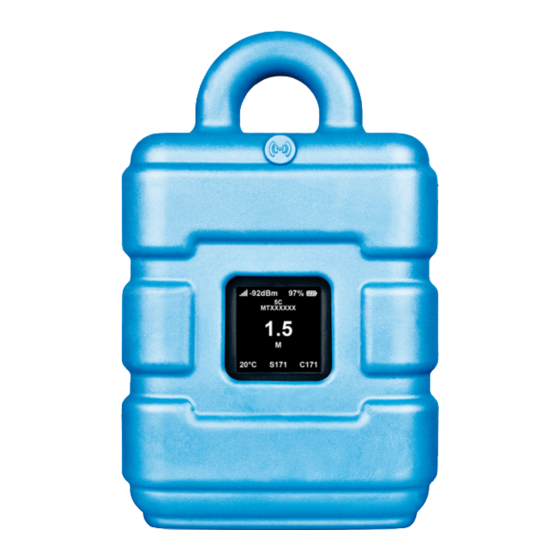
The display of the myDatalogGauge 3G is activated as soon as the reed switch is pressed. The time for which the reed switch was pressed is visualised by a circle in which the segments change from white to green. - Page 77 The status indication during normal operation shows the current fill level in the centre of the display. If several BLE Gauge sensor modules are connected to the myDatalogGauge 3G , the fill levels of the individual BLE Gauge sensor modules are displayed alternately. Based on the currently displayed value, the type designation and serial number for the relevant module are shown in the upper section of the display.
- Page 78 Transport mode, no activation module inserted Reed switch activated Establishing the BLE connection between BLE Gauge and myDatalogGauge 3G Connecting to the myDatanet server Data synchronisation with the myDatanet server in progress In the event of a connection abort, wait until the next...
-
Page 79: User Interface On The Mydatanet Server
2G/3G connection (automatic recharge can take up to 4 hours) E31 ... Signal line between BLE Gauge and the pressure sensor interrupted The batteries of the myDatalogGauge 3G need to be replaced 10.2 User interface on the myDatanet server 10.2.1 Site configuration Note: Depending on the respective user level, some of the configuration fields mentioned in the following sub- chapters may be hidden. -
Page 80: Specific Input Screen For Configuring The Site
10.2.1.1 Specific input screen for configuring the site 10.2.1.1.1 Site "Site" configuration section during normal operation 1 Specifies to which customer the site is assigned 2 Assign site to another customer 3 Site designation (not relevant for the device or data assignment) [2-50 characters] 4 Serial number of the device that is linked to the site (device assignment!) 5 Version number of the IoT application that is currently installed on the site. - Page 81 Chapter 10 User interfaces 11 Indicates that the values for the trimming and sensor offset entered via the "Measurement channels" configuration section (see "Measurement channels" on page 83) have not yet been stored in the BLE Gauge . The symbol is hidden as soon as the values read-back from the BLE Gauge match the values in the "Measurement channels"...
-
Page 82: Setup Data
10.2.1.1.2 Setup data "Setup data" configuration section 1 Opens an illustration to explain the progress of setup mode 2 Status information on the currently active or last executed setup mode 3 Visualisation of the GSM level values measured in the last 35 minutes. The graph may therefore contain the results of several executed setup modes. -
Page 83: Comments
Chapter 10 User interfaces 10.2.1.1.3 Comments "Comments" configuration section 1 Free comment field (is also displayed below the device type in the site list) 10.2.1.1.4 Measurement channels 10.2.1.1.4.1 Basis "Measurement channels" configuration section, "Basis" tab 1 Freely selectable channel designation for the fill level that is recorded by means of the BLE Gauge assigned to the measurement channel 2 Selection of the mode used to assign the BLE Gauge to the corresponding measurement channel automatic... -
Page 84: Alarms
Note: Additional explanation on the zero point adjustment and installation height of the pressure sensor Assumption: Pressure sensor 0-1 m Installation situation of the pressure sensor 1 Installation height: 15 cm 3 Output value of the pressure sensor: 6 cm 2 Pressure sensor 4 Measured fill level: 20 cm Required configuration Parameter... -
Page 85: Trigger
Chapter 10 User interfaces 10.2.1.1.4.3 Trigger There are two types of triggers: Event trigger (RI, XM) The relevant operation (e.g. initiate transmission) is only executed once when the trigger event occurs. Level trigger (RA, QX) The relevant operation (e.g. use alternative record interval) is executed as long as the trigger is active. "Measurement channels"... -
Page 86: Internal Channels
Internal device temperature of the myDatalogGauge 3G Air humidity in the housing of the myDatalogGauge 3G GSM level Service Remaining days until the batteries of the myDatalogGauge 3G need to be replaced Load Energy consumption between two recordings PowerOn Flag Sensor x... -
Page 87: Alarms
Chapter 10 User interfaces 10.2.1.1.5.2 Alarms "Internal channels" configuration section, "Alarms" tab 1 A warning is triggered, if the measurement value drops to or below this value. 2 A warning is triggered, if the measurement value meets or exceeds this value. 3 An alarm is triggered, if the measurement value drops to or below this value. -
Page 88: Alarm Settings
10.2.1.1.6 Alarm settings "Alarm settings" configuration section 1 Selection of how alarms should be acknowledged Standard The global server setting is used to determine whether alarms must be acknowledged automatically or manually (see "myDatanet Server Manual " 805002) automatic Alarms are acknowledged automatically as soon as all of the messages have been sent. If SMS that have a tariff with a delivery confirmation function have also been sent, acknowledgement is provided after delivery confirmation. -
Page 89: Calculated Channels
Chapter 10 User interfaces 10.2.1.1.7 Calculated channels Note: The values of the calculated channels are directly calculated for every data output (display on the myDatanet server or download from the myDatanet server). They are not saved in the server database. 10.2.1.1.7.1 Basis "Calculated channels"... -
Page 90: Calculation
4 Defines the upper scale end of the pointer instruments 5 String that is used as a measurement unit by all of the server display elements [0-16 characters]. It has no direct influence on the values 6 Number of decimal places that are used by all of the server display elements 7 Inverts the input signal (only for calculated channels in "Digital"... -
Page 91: Alarms
Chapter 10 User interfaces "Delta" calculation mode 1 Selection of the channel from which the input data is used 5 Specifies the desired time unit (value/sec., value/min., ...) for the result 6 Offset that is added following multiplication with the "Factor" parameter. The result is converted in to the desired time unit before multiplication with the "Factor"... -
Page 92: Basic Settings
10.2.1.1.8 Basic settings "Basic settings" configuration section 1 Time between transmissions 2 Time between the transmissions, if a alternative transmission cycle should be used because of a trigger being initiated 3 Time between measurement data recordings 4 Time between measurement data recordings, if an alternative record interval should be used because of a trigger being initiated 5 Regional settings (not relevant for raw measurement data as this is stored in UTC) 6 Configuration for automatic time adjustment... -
Page 93: Default Input Screen For Configuring The Site
Chapter 10 User interfaces 9 Selection of the report template used to display the data when clicking on the symbol to display the measurement data, which is located in the list of sites/applications. Only the report templates in which the site/application type of the first wild card is compatible with the site/application that is currently being edited are displayed in the dropdown list. -
Page 94: Alarm Settings
10.2.1.2.3 Alarm settings Acknowledgement Standard The global server setting is used to determine whether alarms must be acknowledged automatically or manually. automatic Alarms are acknowledged automatically as soon as all of the messages have been sent. If SMS that have a tariff with a delivery confirmation function have also been sent, acknowledgement is provided after delivery confirmation. -
Page 95: Basis
Chapter 10 User interfaces 10.2.1.2.4.1 Basis Title 1-5 Freely selectable channel title for the calculated channels [0-16 characters] Mode Possible calculation modes for the calculated channels Calculated channel deactivated Table Defines the lower scale end of the pointer instruments Defines the upper scale end of the pointer instruments Unit String that is used as a measurement unit by all of the server display elements [0-16 characters]. -
Page 96: Calculation
10.2.1.2.4.2 Calculation Calculated channel deactivated Table Source Selection of the channel from which the input data is used Opens the screen for entering the reference point table (the table rows are interpolated linearly, values outside of the defined table are extrapolated linearly.) Digital Source... -
Page 97: Alarms
Chapter 10 User interfaces Note: Additional explanation: Delta mode Assumption: The source channel contains the counter reading of an infinite counter in m . The calculated channel 1 should contain the flow rate in m /s and calculated channel 2 should contain the flow rate in l/h. Required configuration Parameter Value channel 1 Value channel 2... -
Page 98: Basic Settings
10.2.1.2.5 Basic settings Time zone Regional settings (not relevant for raw measurement data as this is stored in UTC) Daylight saving time Configuration for automatic time adjustment Standard The configuration for the time adjustment is adopted by the global server setting. Automatic time adjustment deactivated Predefined setting for the American area Predefined setting for the European area... -
Page 99: Measurement Instrument
Chapter 10 User interfaces 10.2.2.2 Measurement instrument Customer Name of the customer to whom the measurement instrument is assigned Tags List of the tags that are already assigned to the measurement instrument. This assignment can be cancelled by clicking on the cross next to the title of the tag. The input screen for assigning the tags is opened by clicking on the plus symbol. -
Page 100: Gprs
(malfunctions may occur). Identification String specifying the hardware platform implemented in the device and the corresponding hardware version (i.e. the rapidM2M module identification). Hardware version Hardware version of the myDatalogGauge 3G 10.2.2.3 GPRS SIM tariff Selected SIM tariff... -
Page 101: Chapter 11 Deviceconfig
11.1 General The DeviceConfig configuration program can be downloaded free of charge from the following website: www.microtronics.com/deviceconfig The tool is used for configuration, maintenance, fault analysis and synchronisation purposes. It is compatible with all myDatanet devices equipped with a USB interface, wireless M-bus interface or Bluetooth Low Energy. -
Page 102: Installation
11.3 Installation The following chapter describes the installation process in Windows 7. 1. Execute the "InstDeviceConfig.exe" file to start the installation process. Note: Only connect the device or USB BLE-Adapter (300685) to your PC once the installation process has completed as the required drivers are only installed during this process. DeviceConfig setup wizard Rev. - Page 103 2. Follow the instructions of the setup wizard until the following screen is displayed. The following drivers must be installed to ensure correct operation. Installation of the USB drivers for the devices Installation of the drivers for the USB BLE-Adapter Installation of the USB drivers for the devices on a M1 basis Installation of the USB drivers for the devices on a M2/M3 basis Rev.
-
Page 104: Installing The Drivers For The Usb Ble-Adapter
3. Once the following screen is displayed, close the installation process by clicking on the "Finish" button. Complete the setup 11.3.1 Installing the drivers for the USB BLE-Adapter Note: Information on the USB BLE-Adapter (300685) is provided in chapter "USB BLE-Adapter " on page 108. -
Page 105: Menu Of The Deviceconfig
11.4 Menu of the DeviceConfig 11.4.1 Settings "Settings" menu item 11.4.1.1 Options The settings for the COM ports to which the USB radio transmitter (206.657) or the USB BLE-Adapter (300685) are connected can be specified and the automatic search for the available firmware versions can be activated or deactivated via the "Settings ->... - Page 106 "Settings -> Options" menu item 1 Activates/deactivates the automatic search for the 4 COM port that is connected with the USB radio USB radio transmitter (206.657) on all of the transmitter (206.657) (only visible when the available COM ports automatic search is deactivated) 2 Activates/deactivates the automatic search for the 5 COM port that is connected with the USB BLE- USB BLE-Adapter (300685) on all of the available...
-
Page 107: Functional Principle (Communication With A Mydataloggauge 3G )
The DeviceConfig configuration program communicates wirelessly (Bluetooth Low Energy) with the myDatalogGauge 3G using the USB BLE-Adapter (300685). The functions provided with the DeviceConfig configuration program include: Read out and analysis of the device log (see ""Log" tab" on page 110) Update the firmware(see ""Firmware"... -
Page 108: Usb Ble-Adapter
11.5.1 USB BLE-Adapter The USB BLE-Adapter (300685) is not included in the scope of delivery of the myDatalogGauge 3G . It is required because standard PCs and laptops often do not have a Bluetooth Low Energy interface that is necessary for communication with the myDatalogGauge 3G . -
Page 109: Gsm" Tab
Note: To ensure a stable connection, the wireless signal level should be higher than -90dBm , i.e. for example -85dBm . This is achieved by reducing the distance between the myDatalogGauge 3G and , and avoiding obstacles such as walls and similar. -
Page 110: Log" Tab
11.5.4 "Log" tab This tab is designed to manage log entries. It enables the entries to be loaded from the myDatalogGauge 3G , to be saved as a *.tsv file and entries to be deleted from the memory of the myDatalogGauge 3G . - Page 111 Colour Evaluation White Information regarding the current operating state Green Light blue Blue Purple Grey Yellow Uncritical error Critical error "Log" tab with detailed view activated 1 Activates the detailed display of the log entries 3 Log entry that is always displayed 2 Informative log entry that is only visible if the detailed display is activated Rev.
-
Page 112: Firmware" Tab
11.5.6 "Sync" tab This area is designed to synchronise measurement data and configurations between myDatalogGauge 3G , DeviceConfig and myDatanet server. The "Sync" tab is also available if there is no connection (USB, wireless M-bus or Bluetooth) to a device. -
Page 113: Existing Connection To The Mydataloggauge 3G
11.5.6.1 Existing connection to the myDatalogGauge 3G If there is an existing connection to the myDatalogGauge 3G , there is an option to only synchronise the measurement data and configurations with the DeviceConfig configuration program for local processing or to transfer them to the myDatanet server. -
Page 114: No Connection To A Device
11.5.6.2 No connection to a device This option can be used to complete the synchronisation retrospectively, if no connection to the Internet was possible while reading out the measurement data and configurations from the myDatalogGauge 3G . "Sync" tab without connection to a device... -
Page 115: Recommended Procedure
"Creating the site" on page 131. Another prerequisite for this is that your PC is connected to the Internet while reading out the data from the myDatalogGauge 3G . If this is not possible, follow the procedure described in chapter "No Internet connection when reading out the data" on page 119. - Page 116 5. Place a tick in the "Sync with server" checkbox. This checkbox is only visible if your PC is currently connected to the Internet. "Sync" tab when connected to the myDatalogGauge 3G 1 Checkbox to determine whether the measurement data and configurations should also be synchronised with the server when clicking on the Sync button.
- Page 117 3G " on page 116). When you read out the data for the first time from a myDatalogGauge 3G , you can choose whether all of the saved data or only the data from a certain date onwards are read out from the myDatalogGauge 3G .
- Page 118 After clicking on "OK", the option to select from which time period onwards the data should be read out opens. The measurement data is read out from the myDatalogGauge 3G in accordance with the selection and assigned to the new site.
-
Page 119: No Internet Connection When Reading Out The Data
This procedure is recommended, if an Internet connection cannot be established on the site while reading out the data from the myDatalogGauge 3G . During this procedure, the data on the site is initially only synchronised with the DeviceConfig configuration program. The data is then transferred to the myDatanet server at a later date when your PC has re-established a connection to the Internet. - Page 120 When you read out the data for the first time from a myDatalogGauge 3G , you can choose whether all of the saved data or only the data up to a certain date are read out from the myDatalogGauge 3G .
- Page 121 Selecting the time period for which the data should be read out (only during first synchronisation) 1 Read out all of the saved data Note: Reading out all of the saved data can take several hours depending on the number of saved measurement data records.
- Page 122 9. Select the "Sync" tab and click on the button to trigger synchronisation. "Sync" tab without connection to a device 1 Button to trigger synchronisation During this process, the measurement data and configurations of all of the devices that the DeviceConfig configuration program has saved locally are synchronised with the myDatanet server.
-
Page 123: Functional Principle (Communication With A Ble Gauge Sensor Module)
11.6 Functional principle (communication with a BLE Gauge sensor module) The following description particularly relates to the use of the DeviceConfig configuration program in conjunction with a BLE Gauge sensor module. Functional principle 1 BLE Gauge sensor module 3 PC with the DeviceConfig configuration program installed 2 USB BLE-Adapter The DeviceConfig configuration program communicates wirelessly (Bluetooth Low Energy) with the BLE... -
Page 124: Establishing A Connection To A Sensor Module With Bluetooth Low Energy Interface
11.6.1 Establishing a connection to a sensor module with Bluetooth Low Energy interface The USB BLE-Adapter (300685) is required to establish a connection to a sensor module with a Bluetooth Low Energy interface. First of all complete the steps described in chapter "Installing the drivers for the USB BLE-Adapter "... - Page 125 4. Wait until the DeviceConfig has received the configuration of the sensor module. Depending on the sensor module, additional tabs may be displayed. "Instrument" tab when actively connected to the sensor module 1 Radio signal strength [dBm] Note: To ensure a stable connection, the wireless signal level should be higher than -90dBm , i.e. for example -85dBm .
-
Page 126: Firmware" Tab
11.6.2 "Firmware" tab This tab enables firmware to be installed directly via the Bluetooth Low Energy interface. "Firmware" tab 1 Currently installed software version 2 Button to install a previously downloaded firmware package Rev. 01... -
Page 127: Chapter 12 Mydatanet Server
Chapter 12 myDatanet server Chapter 12 myDatanet server Note: All of the screenshots show version 47.1 of the myDatanet server using the standard colour scheme. Newer versions may include minor changes to the appearance of the server. 12.1 Overview Overview of the myDatanet server 1 Freely selectable logo 5 Opens the screen to input the global settings for the server... -
Page 128: Customer" Area
12.2 "Customer" area Overview of the "Customer" area 1 Area where an image file can be displayed as a "Map" and/or the OpenStreetMaps map can be displayed The sites can be manually placed on the image file used as a "map". In the OpenStreetMaps map, the sites are only displayed once GPS coordinates have been assigned to the site. - Page 129 Chapter 12 myDatanet server 3 List of tags that are assigned to at least one of the customers displayed in the list of customers. If the list of customers was limited by the search field or selection of a tag, this is taken into consideration when creating the list of tags.
-
Page 130: Site" Area At Customer Level
12.3 "Site" area at customer level Overview of the "Sites" area at customer level 1 Area where an image file can be displayed as a "Map" and/or the OpenStreetMaps map can be displayed The sites can be manually placed on the image file used as a "map". In the OpenStreetMaps map, the sites are only displayed once GPS coordinates have been assigned to the site. -
Page 131: Reports
Chapter 12 myDatanet server 4 Symbol that represents a site on the "Map" 5 Symbol via which a OpenStreetMaps map, on which the sites are displayed, can be loaded. (see "Map view" on page 131) 6 Symbol via which an image file can be loaded on to the server as a "Map" To remove the "Map"... - Page 132 2. Click on the "Customer" menu item of the myDatanet server to call up the list of available customers. Select an existing customer or create a new customer. Selecting the customer 1 Menu item to call up the list of customers 3 List of available customers 2 Creating a new customer 3.
- Page 133 Chapter 12 myDatanet server 4. If necessary, change the suggested name of the site, select the desired site type or the desired application from the drop-down list and then click the "Add" button. Completing site creation 1 Name of the site (freely selectable) 3 "Add"...
-
Page 135: Chapter 13 Api
Chapter 13 API Chapter 13 API Important note: The relevant licences are required on the myDatanet server to use the API (Application Programming Interface). For future information contact your responsible sales partner. 13.1 Backend API The API is provided to export data from and import data to the myDatanet server. However, this is not just limited to the pure measurement data but includes all of the data provided by myDatanet server (e.g. -
Page 136: Overview
13.2.1 Overview rapidM2M Playground Opens the login dialogue of the myDatanet server linked to the rapidM2M Playground 1 Input field for the user name 2 Input field for the password 3 List of the available HTTP commands. The HTTP commands are grouped according to their fields of application. -
Page 137: Chapter 14 Maintenance
The remaining days until the next time the batteries need to be replaced are shown on the display of the myDatalogGauge 3G (see "Display" on page 76). The batteries must only be replaced by the manufacturer (see "Contact information" on page 157) or a certified service partner. - Page 138 BLE Gauge must be replaced is shown on the display of the myDatalogGauge 3G (see "Display" on page 76). Rev. 01...
-
Page 139: Chapter 15 Removal/Disposal
Logo of the EU WEEE Directive This symbol indicates that the requirements of Directive 2012/19/EU regarding the scrap disposal of waste from electric and electronic equipment must be observed. Microtronics Engineering GmbHsupports and promotes recycling and environmentally friendly, separate collection/disposal of waste from electric and electronic equipment in order to protect the environment and human health. -
Page 141: Chapter 16 Troubleshooting And Repair
Communication Evaluate the error code shown on the display (see "Display" on page 76). Load the device log from the myDatalogGauge 3G or the myDatanet server problems (between and use DeviceConfig for the report (see "Evaluating the device log" on myDatalogGauge page 150). - Page 142 Problem Cause/solution Fill level is not plausible. Check whether there are any kinks in the cable between the BLE Gauge and the pressure sensor or whether the bend radius has fallen below the minimum permissible value of 60mm . Check the pressure compensation membrane of the BLE Gauge for any impurities (see "Overview"...
-
Page 143: Log Entries And Error Codes
Chapter 16 Troubleshooting and repair 16.2 Log entries and error codes Log entry Parameter Description Code Plain text Code Plain text 1000 POWER ON Restart following a power failure Watchdog reset (e.g. because of an exception) Reset was initiated by the device itself (e.g. in event of firmware update) Restart for another reason. - Page 144 Log entry Parameter Description Code Plain text Code Plain text 1039 UV MODEM The rechargeable battery or battery voltage once RECOVER again suffices to guarantee a stable connection. This is achieved by replacing the rechargeable battery or battery pack . 1161 LOG Error in file system has been resolved.
- Page 145 Chapter 16 Troubleshooting and repair Log entry Parameter Description Code Plain text Code Plain text 1317 BLE CONNECTED Bluetooth connection to a PC established 1318 BLE Bluetooth connection was terminated DISCONNECTED 1601 SIM_STATE NONE SIM state was changed to "NONE" (initial state) PRODUCTION SIM state was changed to "PRODUCTION"...
-
Page 146: Modem Error
FAILED Try to improve the position of the antenna. Check whether the device is in the coverage area (www.microtronics.com/footprint). 1200 BAND SEL FAILED -969 --- A network could not be found on the GSM900/1800 or on the GSM850/1900 band. Try to improve the position of the antenna. - Page 147 1200 NETLOCK ERROR -966 Error when selecting the network. Check whether the device is in the coverage area. Internal SIM chip: see www.microtronics.com/footprint TCP channel error 1200 CHANNEL -965 --- An attempt is being made to write to/read a TCP ABORTED client that is no longer available.
-
Page 148: Module-Specific Critical Errors
Description Code Plain text Code Plain text 2200 Service interval The batteries of the myDatalogGauge 3G need gateway to be replaced 2201 Service interval Battery of the BLE Gauge , that is assigned to sensor measurement channel 1, needs to be replaced Battery of the BLE Gauge , that is assigned to measurement channel 2, needs to be replaced... -
Page 149: Module-Specific Information Regarding The Current Operating State
Plain text 2400 Activation module The activation modules has been removed from has been removed the sensor recess of the myDatalogGauge 3G . Activation module The activation module has been inserted in the has been inserted sensor recess of the myDatalogGauge 3G . -
Page 150: Evaluating The Device Log
The DeviceConfig program can be used to read all of the stored log entries, including those that have not yet been transferred to the myDatanet server, directly from the myDatalogGauge 3G via the Bluetooth interface. A more detailed description about the evaluation of the device log using DeviceConfig is included in the user manual for the DeviceConfig ("myDatanetDeviceConfig Manual "... -
Page 151: Chapter 17 Spare Parts And Accessories
Chapter 17 Spare parts and accessories Chapter 17 Spare parts and accessories 17.1 Assembly sets Description Quantity Order number Niro shackle 206.325 BLE Gauge mounting fixture 300881 17.2 Antennas Description Quantity Order number Flat antenna Smart Disc Multi Band FME-F 2m 300629 Multi band antenna with bracket 300787... -
Page 153: Chapter 18 Document History
Chapter 18 Document history Chapter 18 Document history Rev. Date Changes 16.04.2021 First version Rev. 01... -
Page 155: Chapter 19 Glossary
The manufacturer's devices are equipped with subscriber identity modules (SIM) ex-works for the purpose of mobile data transmission. The footprint describes those countries and regions where a mobile connection is available (see www.microtronics.com/footprint). Device logic The device logic is the intelligence installed on the device that determines the local functionality of the device. - Page 156 rapidM2M Store Is responsible for distributing the app models to the individual myDatanet servers. When installing and updating IoT apps the myDatanet server access the app models provided in the rapidM2M Store . The developer of the respective app model defines which myDatanet servers are allowed to access an app model via the rapidM2M Studio .
-
Page 157: Chapter 20 Contact Information
Chapter 20 Contact information Chapter 20 Contact information Support & Service: Microtronics Engineering GmbH Hauptstrasse 7 3244 Ruprechtshofen Austria, Europe Tel. +43 (0)2756 7718023 support@microtronics.com www.microtronics.com Microtronics Engineering GmbH (Headquarters) Hauptstrasse 7 3244 Ruprechtshofen Austria, Europe Tel. +43 (0)2756 77180 Fax. - Page 158 Certified by TÜV AUSTRIA: EN ISO 9001:2015, EN ISO 14001:2015, EN ISO 50001:2011 for myDatanet | TÜV SÜD: ATEX Directive 2014/34/EU © Microtronics Engineering GmbH. All rights reserved. Photos: Microtronics Microtronics Engineering GmbH | www.microtronics.com Hauptstrasse 7 | 3244 Ruprechtshofen | Austria | +43 2756 77180 | office@microtronics.com 301134 | Rev.01...
Need help?
Do you have a question about the myDatalogGauge 3G and is the answer not in the manual?
Questions and answers