
Subscribe to Our Youtube Channel
Related Manuals for Microtronics myDatalogNANO


Summary of Contents for Microtronics myDatalogNANO
-
Page 1: Cover
User manual myDatalogNANO Cover Valid from: Firmware version: 03v003 Modem Version: 03v002 Server version: 40.1 Hardware version: 2.0 300357 | Rev.02... -
Page 3: Table Of Contents
Chapter 1 Table of contents Chapter 1 Table of contents Cover Chapter 1 Table of contents Chapter 2 Declaration of conformity Chapter 3 Technical data Chapter 4 General specifications 4.1 Translation 4.2 Copyright 4.3 General descriptive names 4.4 Safety instructions 4.4.1 Use of the hazard warnings 4.4.2 General safety instructions 4.4.3 Safety and preventative measures for handling GSM/GPRS modems... - Page 4 6.2 Scope of supply 6.3 Storage 6.4 Transport 6.5 Return Chapter 7 Installation 7.1 Dimensions 7.2 Installing the myDatalogNANO 7.2.1 Wall mounting 7.2.2 Top-hat rail assembly 7.2.3 Pipe assembly 7.3 Safety instructions for the cabling 7.3.1 Information on preventing electrostatic discharges (ESD) 7.4 Electrical installation...
- Page 5 8.1 User information 8.2 General principles 8.3 Commissioning the system 8.4 Testing communication with the device Chapter 9 User interfaces 9.1 User interface on the myDatalogNANO 9.1.1 Operating elements 9.1.1.1 Solenoid switch 9.1.1.2 Status LED 9.2 User interface on the myDatanet server 9.2.1 Site configuration...
- Page 6 9.2.1.7 Alarm settings 9.2.1.8 Basic setting 9.2.1.9 FTP export settings 9.2.2 Device configuration 9.2.2.1 Comments 9.2.2.2 Measurement instrument 9.2.2.3 Device-specific settings 9.2.2.4 GPRS Chapter 10 myDatanet server 10.1 Overview 10.1.1 Explanation of the symbols 10.2 "Customer" area 10.3 "Site" area at customer level 10.3.1 Reports 10.3.2 Groups 10.3.3 Map view...
- Page 7 Chapter 1 Table of contents 14.3.2 Evaluating the device log using DeviceConfig Chapter 15 Spare parts and accessories 15.1 Assembly sets 15.2 Antennas 15.3 Battery packs 15.4 Cable 15.5 Other accessories Chapter 16 Application example 16.1 Measuring the heat quantity (in heating systems) 16.1.1 Requirements 16.1.2 Required configuration 16.2 Flow rate measurement (in lines)
-
Page 9: Chapter 2 Declaration Of Conformity
Chapter 2 Declaration of conformity Chapter 2 Declaration of conformity Rev. 02... -
Page 11: Chapter 3 Technical Data
Data type f32(32 Bit floating point) Data transmission By means of GSM/GPRS quad-band modem to the respective myDatanet server The myDatalogNANO is equipped with an integrated SIM chip. Monthly data t.b.d. at two-minute measurement cycle and 120-minute transmission cycle volume... -
Page 13: Chapter 4 General Specifications
4.4 Safety instructions For the connection, commissioning and operation of the myDatalogNANO , the following information and higher legal regulations of the country (e.g. ÖVE), such as valid EX regulations as well as the applicable safety and accident prevention regulations for the respective application case must be observed. -
Page 14: Use Of The Hazard Warnings
4.4.1 Use of the hazard warnings DANGER: Indicates a potential or threatening hazardous situation that will result in death or serious injuries if not avoided. WARNING: Indicates a potential or threatening hazardous situation that can result in death or serious injuries if not avoided. -
Page 15: Safety And Precautionary Measures For The Installation Of The Gsm/Gprs Modem
Chapter 4 General specifications In addition to the following safety considerations, all directives of the country in which the device is installed must be complied with. Important note: No liability shall be assumed at any time and under no circumstances for connections via a GSM/GPRS modem for which wireless signals and networks are utilized. -
Page 16: Overview
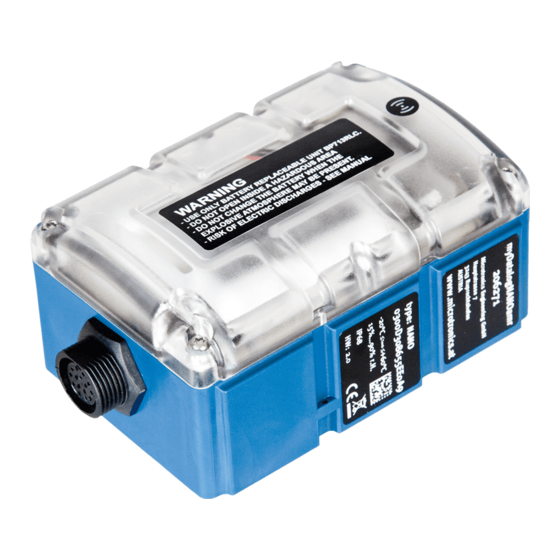
4.5 Overview Overview myDatalogNANO 1 Housing cover 3 Sensor connector 2 Antenna connector Rev. 02... -
Page 17: Block Diagram
Chapter 4 General specifications 4.5.1 Block diagram Block diagram of the myDatalogNANO Rev. 02... -
Page 18: Intended Use
A Managed Service contract with Microtronics Engineering GmbH is required for use of the mobile data transmission (see www.microtronics.com/managedservice). This includes the provisioning of the mobile communications connection via the network of the service provider included in the above-mentioned list. -
Page 19: Device Labelling
Chapter 4 General specifications 4.8 Device labelling The specifications in this user manual apply exclusively to the myDatalogNANO device type. The type plates are located on the right side of the device and contain the following specifications: Type designation Item number... -
Page 20: Storage Of The Product
4.10 Storage of the product To store the myDatalogNANO , activate the transport lock, by setting the "Operation mode" in the input screen of the myDatanet server for configuring the device (see "Device-specific settings" on page 91) to "OFF". Then activate ALOHA transmission mode (see "ALOHA transmission mode" on page 32) via the solenoid switch so that the amended configuration is transferred to the myDatalogNANO . - Page 21 Chapter 4 General specifications Note: Qualified personnel In the context of these instructions and the warnings on the product itself, individuals responsible for the setup, installation, commissioning and operation of the product must have gained relevant qualifications relating to their activities, including, for example: Training, instruction and authorisation to activate/deactivate, ground and label electric circuits and devices/systems in accordance with the standards of safety engineering.
-
Page 23: Chapter 5 Functional Principle
Functional principle myDatalogNANO with integrated managed service SIM chip (including data transmission) myDatanet server to which the data is transferred Client that accesses the interface of the myDatanet server via the web browser Customer-specific server that provides clients with their own interface. - Page 24 Functions and components provided by myDatanet : myDatalogNANO The myDatalogNANO is a portable device for connecting sensors (UI1-5) to the myDatanet server (GPRS). Managed Service Managed Service is the basis for operating your devices and provides you with a wide range of services.
-
Page 25: Internal Processing Of The Measurement Values
Chapter 5 Functional principle 5.1 Internal processing of the measurement values Diagram of the internal processing of the measurement values 1 Filter to compensate for brief signal fluctuations 5 Module to maintain the last valid value in the event (see "Filter module" on page 26). The filter of invalid measurement values (see "Hold module is operated permanently. -
Page 26: Filter Module
5.1.1 Filter module The filter module is designed to compensate for brief fluctuations to the input signal. This module is only available for the 5 universal inputs. The following table specifies the relevant parameters for the module: Configuration section Mode Parameter Explanation Measurement channels ->... -
Page 27: Overflow Module
Chapter 5 Functional principle 5.1.2 Overflow module This module monitors the measurement range limits of the raw value. If a universal input was, for example, switched to "Voltage" mode, a raw value of 2.1V will violate the measurement range. The overflow module is only available for the 5 universal inputs in the "Freq", "PWM", "Voltage, type 0-2V", "Voltage, type 0-20mA adapter", "PT1000", "KTY81110", "KTY81210", "NI1000"... -
Page 28: Scale Module
5.1.3 Scale module This module rescales the raw value (e.g. frequency) to the required measurement value (e.g. mm). The scale module is only available for the 5 universal inputs. The following table specifies the relevant parameters for the module: Configuration section Mode Parameter Explanation... -
Page 29: Hold Module
Chapter 5 Functional principle 5.1.5 Hold module With the help of the hold module, it can be determined how to proceed in the event of invalid measurement values. It ensures the last valid measurement value is retained until a new valid measurement value is available or passes the error on after a certain number of invalid measurements. -
Page 30: Record Module
5.1.7 Record module The record module records the measurement values. As the record interval and measurement cycle can be selected individually, a record is not completed at the time of every measurement. Depending on the global triggers set by the alarm/trigger module (see "Alarm flags" on page 31 or "Trigger flags" on page 31), the record interval is modified, the transmission is initiated or a new measurement is triggered, if necessary. -
Page 31: Alarm Flags
Chapter 5 Functional principle 5.1.7.1 Alarm flags const // Warning MDN_FLG_WARNING = 0b00000001, // Alarm MDN_FLG_ALARM = 0b00000010, // Technical error of low priority MDN_FLG_FAULTLOW = 0b00000100, MDN_FLG_FAULTHIGH = 0b00001000, // Technical error of high priority // Shortfall of the alarm level MDN_FLG_UNDERFLOW = 0b10000000, /* Must be set if the value is below the threshold. -
Page 32: Aloha Transmission Mode
5.2 ALOHA transmission mode ALOHA transmission mode is a special connection mode whereby the myDatalogNANO establishes a connection to the myDatanet server for a period of time configured via the "Basic settings" configuration section (see "Aloha/wakeup duration" in chapter "Basic setting" on page 87). -
Page 33: Automatic Selection Of The Gsm Network
5.3 Automatic selection of the GSM network The GSM network to which the device should register must be selected, as the myDatalogNANO is equipped with a SIM chip that provides a mobile connection via a variety of international service providers (see www.microtronics.com/footprint). -
Page 35: Chapter 6 Storage, Delivery And Transport
Magnetic antenna TNC-M 3m (300248 ) BP713RLC Battery (300247) The battery pack (BP713RLC Battery ) was already inserted in the myDatalogNANO during production. Additional accessories such as assembly sets, antennas, battery packs, sensors, etc. depending on the order specifications. Please check these against the delivery slip. - Page 36 Marking and labelling (e.g. transport stickers) Documentation (e.g. ADR transport documents or Dangerous Goods Declaration) The energy stores of the myDatalogNANO as well as the replacement battery pack are lithium batteries. The following points must therefore be observed in conjunction with transporting lithium batteries:...
-
Page 37: Return
Support & Service Centre (see "Contact information" on page 131). The return shipment of the myDatalogNANO must occur in the original packaging and with freight and insurance paid to Microtronics Engineering GmbH (see "Contact information" on page 131). Insufficiently cleared return shipments will otherwise not be accepted! Rev. -
Page 39: Chapter 7 Installation
7.2 Installing the myDatalogNANO Important note: Ensure installation is completed correctly. Comply with existing legal and/or operational directives. Improper handling can cause injuries and/or damage to the devices. The myDatalogNANO must not be operated in the field with the lid open. Rev. 02... -
Page 40: Wall Mounting
206.640) 1. First attach the assembly loop (3) using the screws (2) included in the "Universal bracket for housing myDatanet 86x126 (206.640)" equipment set to the myDatalogNANO (see "Step 1 of the wall mounting" on page 40). - Page 41 If you are using your own screws, you must also insert the wall plugs into the holes before mounting the myDatalogNANO with the attached assembly loop (3) to the wall (see "Step 2 of the wall mounting" on page 40).
-
Page 42: Top-Hat Rail Assembly
1. First attach the assembly loop (3) using the screws (2) included in the "DIN rail mounting set for myDatanet housing 86x126 (206.634)" equipment set to the myDatalogNANO (see "Step 1 of the top- hat rail assembly " on page 42). -
Page 43: Pipe Assembly
86x126 (206.660)" equipment set to the myDatalogNANO (see "Step 1 of the pipe assembly " on page 43). 2. Position the myDatalogNANO with the attached assembly loop (3) on the pipe and use the supplied cable binders (4) to secure the myDatalogNANO (see "Step 2 of the pipe assembly" on page 43). -
Page 44: Safety Instructions For The Cabling
7.3 Safety instructions for the cabling When connections are made to the myDatalogNANO , the following warnings and information must be observed, in addition to the warnings and information found in the individual chapters on the installation. Further safety information is included in "Safety instructions" on page 13. - Page 45 Chapter 7 Installation Connecting the sensors when using "Cable set NANO Connecting the sensors universal " (300250) 1 Sensor connector (15-pin connector) connector) 2 Cable set NANO universal (300250) Sensor connector (pin Sensor connector (15-pin Cable set NANO Signal assignment) connector) connector) universal (300250) n.c.
-
Page 46: Connection Examples
(see "Status LED" on page 64), indicating that a connection is being established. Note: If the myDatalogNANO is still in transport mode, the transport lock is deactivated by the initiation of ALOHA transmission mode and the device starts to operate in accordance with the configuration. -
Page 47: Use Of The Clamping Tubes
7.4.1.3 Using Pressure compensation tube with 1x 0/4-20mA 24VDC " (300255 ) myDatalogNANO with connected Pressure compensation tube with 1x 0/4-20mA 24VDC (300255 ) 1 myDatalogNANO 2 Pressure compensation tube with 1x 0/4-20mA... - Page 48 Important note: The sensor cable must also be cleaned to guarantee the tightness of the cable screw connection. Connecting the sensor 6. Carefully push the 0/4-20mA board into the pressure compensation clamping tube and tighten the connecting nut of the cable screw connection facing the myDatalogNANO . Rev. 02...
-
Page 49: Connecting The Gsm Antenna
The standard antenna is directly attached to the antenna connector (see "Overview" on page 16) of the myDatalogNANO . 1. Connect the antenna directly to the antenna cable of the myDatalogNANO (see "Overview" on page 16). Important note: Do not apply too much force when tightening the antenna. Do not use any tools to tighten the antennas;... -
Page 50: Possibilities For Improving The Signal Quality
7.4.3.3 Procedure for determining the optimum position of the antenna 1. Install the myDatalogNANO as described in chapter "Installing the myDatalogNANO " on page 39. During this process, also observe the notes regarding the influences on the signal quality (see "Typical influences on the signal quality"... -
Page 51: Technical Details About The Universal Inputs
The "Pressure compensation tube with 1x 0/4-20mA 24VDC " (300255 ) enables a 2-wire mA sensor to be connected to the myDatalogNANO without additional accessories. A detailed description of this is provided in "Using Pressure compensation tube with 1x 0/4-20mA 24VDC " (300255 )" on page 47. -
Page 52: Voltage 0
This increases the energy requirement and reduces the device operating time. Schematic diagram: Universal input in one of the digital modes 1 myDatalogNANO 2 Equivalent circuit diagram for the switch contact Rev. 02... -
Page 53: Temperature Modes (Pt1000, Kty81110, Kty81210, Ni1000, Tk5000)
If a universal input is operated in one of the temperature modes, a temperature sensor can be connected directly to the universal input without an additional energy supply. Schematic diagram: Universal input in one of the temperature modes 1 myDatalogNANO 2 Compatible temperature sensor Typ. resolution 0,5°C (depending on the sensor used) -
Page 54: Technical Details About The "Switchable Sensor Supply (Vout)
The accuracy of <=3.0°C for the standard measurement range (-20...+80°C ) only applies if an offset adjustment has been completed. For this purpose, the measurement value displayed on the myDatanet server must be compared to a reference measurement and the difference must be entered as the "Sensor offset"... - Page 55 Chapter 7 Installation Note: Example to explain the connection between the warmup time and the measurement cycle (warmup time < measurement cycle): Basic setting Measurement cycle 1min. Output channels Ext warmup time Unit sec. Output on the device Sensor supply Explanation: The sensor supply is activated before the actual time of the measurement in accordance with the warmup time.
- Page 56 Note: Example to explain the burst interval in conjunction with the ext. warmup time (ext. warmup time < measurement cycle): warmup time (ext. warmup time < measurement cycle): Basic setting Record interval 5min. Burst interval 60 sec. Measurement cycle 15 sec. Output channels Ext warmup time Unit sec.
-
Page 57: Technical Details About The Device Operating Time
7.4.6 Technical details about the device operating time Note: It must be noted that if the transport lock is activated, the myDatalogNANO uses a certain, albeit low, amount of energy even during storage. This means that if a device has already been stored for a prolonged period it may not achieve the full operating times. -
Page 59: Chapter 8 Initial Start-Up
65). Take the opportunity to get to know the functions of the device in a stable environment. You can also use suitable test signals to simulate the sensors to establish the optimum configuration of the myDatalogNANO prior to its actual first use. This reduces the amount of time required for on-site installation to a minimum. - Page 60 99). 6. Link the myDatalogNANO with the created site (see "Site" on page 65 or "Creating the site" on page 97 7. Activate the ALOHA transmission mode (see "ALOHA transmission mode" on page 32) again so that the site configuration is transferred to the myDatalogNANO .
-
Page 61: Testing Communication With The Device
2. Configure the created site according to your requirements (see "Site configuration" on page 65). 3. Link the myDatalogNANO with the created site (see "Site" on page 65). 4. Initiate the Aloha transmission mode (see "ALOHA transmission mode" on page 32) so that the site settings are transferred to the myDatalogNANO . - Page 62 8. Check the incoming data in the Aloha data window of the myDatanet server, which can be accessed by clicking on the speech bubble with the "Aloha" inscription (see "myDatanet Server Manual " 805002). Particular attention must be paid to the internal " GSM level" measurement value. Note: Additional explanation about evaluating the "GSM level": "GSM level"...
-
Page 63: Chapter 9 User Interfaces
The MDN Magnet (206.803), that is available as an accessory, is required to operate the solenoid switch. The solenoid switch can be used to initiate the Aloha transmission mode or to instruct the myDatalogNANO to immediately issue the error/status code. -
Page 64: Status Led
Description Solution/cause code Transport lock (GPRS OFF, measurement If the Aloha transmission mode is initiated by OFF) solenoid switch, the myDatalogNANO switches back into "RUN" mode (GPRS ON, measurement ON). Last connection OK Last transmission faulty Try again later Standby (GPRS ON, measurement OFF) see "transport lock"... -
Page 65: User Interface On The Mydatanet Server
Chapter 9 User interfaces 9.2 User interface on the myDatanet server 9.2.1 Site configuration Note: Depending on the respective user level, some of the configuration fields mentioned in the following sub- chapters may be hidden. In this case, please contact the administrator of the myDatanet server. Click on the name of the site in the list of sites to open the input screen for configuring the site (see "myDatanet Server Manual "... - Page 66 Mode Basic settings for the measurement channel Universal inputs Measurement channel deactivated Digital Invert Inverts the input signal (digital modes) Cnt.Day Pulse Metered measurand of a pulse in the measurement unit Defines the upper scale end of the pointer instruments Unit String that is used as a measurement unit by all of the server display elements [0-16 characters].
- Page 67 Chapter 9 User interfaces Universal inputs Voltage 0-2V 0...2V voltage mode Start of the measurement range in (analogue modes) the measurement unit 100% End of the measurement range in the measurement unit Unit String that is used as a measurement unit by all of the server display elements [0- 16 characters].
- Page 68 Universal inputs PT1000 Defines the lower scale end of the pointer instruments (Temperature Defines the upper scale end of the pointer modes) instruments Unit Selection of the temperature unit used by all of the server display elements Decimal Number of decimal places that are used by all of the places server display elements KTY81110 Min...
-
Page 69: Config
Chapter 9 User interfaces 9.2.1.3.2 Config Universal inputs Digital Filter time Time in [ms] during which the signal must remain constant to (digital modes) initiate a level change. Used to suppress brief faults (debouncing). Decay Temporal function in the measurement cycle Decay deactivated Minimum signal length for x seconds with a rising edge... - Page 70 Universal inputs Cnt.Day Filter time Time in [ms] during which the signal must remain constant to initiate a level change. Used to suppress brief faults (Counter modes) (debouncing). Reset at Reset time of the day counter Cnt.Intervl. Filter time Time in [ms] during which the signal must remain constant to initiate a level change.
- Page 71 Chapter 9 User interfaces Universal inputs Freq Filter time Time in [ms] during which the signal must remain constant to initiate a level change. Used to suppress brief faults (Frequency mode) (debouncing). Decay Temporal function in the measurement cycle Decay deactivated The minimum of the last x measurement values is recorded.
- Page 72 Universal inputs Filter time Time in [ms] during which the signal must remain constant to initiate a level change. Used to suppress brief faults (PWM mode) (debouncing). Decay Temporal function in the measurement cycle Decay deactivated The minimum of the last x measurement values is recorded.
- Page 73 Chapter 9 User interfaces Universal inputs Voltage 0-2V Filter time Time in [ms] during which the analogue signal is averaged for signal smoothing. Used to (Voltage mode 1/4) (1/4) (1/2) suppress signal noise. Decay Temporal function in the measurement cycle Decay deactivated The minimum of the last x measurement values is recorded.
- Page 74 Universal inputs Voltage 0-2V Out of Procedure in the event of measurement range range violations (Voltage mode 2/4) (2/4) (2/2) Ignore The measurement value is calculated beyond the range limits. Silent cutoff The measurement value is truncated at the range limits. Out of If the measurement value is range...
- Page 75 Chapter 9 User interfaces Universal inputs Voltage 0-20mA Hold Hold the last valid measurement value for x adapter measurement cycles (Voltage mode 3/4) (3/4) Function deactivated (2/2) Number of measurement cycles for which the measurement value is held until the error value is issued In the event of an error, the last valid measurement value is held...
- Page 76 Universal inputs Voltage 4-20mA Time Decay period. Up to a maximum of 60 adapter measurement values c an be used for the (Voltage mode 4/4) (4/4) (2/2) calculation (e.g. 1 channel: 60 measurement values; ... 4 channels: 15 measurement values each). To calculate the number of measurement values that are taken into account, refer to "Example to clarify the record interval, measurement cycle and burst interval...
- Page 77 Chapter 9 User interfaces Note: Additional explanation regarding the installation height of the sensor Assumption: Measurement range of the 4-20mA pressure sensor 0-5m. Please note that an mA sensor requires the optional accessory "Pressure compensation tube with 1x 0/4-20mA 24VDC " (300255 ). Installation situation of the pressure sensor 1 Installation height: 15 cm 3 Output value of the sensor: 5cm...
- Page 78 Universal inputs PT1000 Filter time Time in [ms] during which the analogue signal is averaged KTY81110 for signal smoothing. Used to suppress signal noise. (Temperature KTY81210 Decay Temporal function in the measurement cycle modes 1/2) NI1000 Decay deactivated TK5000 The minimum of the last x measurement (1/2) values is recorded.
-
Page 79: Alarms
Chapter 9 User interfaces Universal inputs PT1000 Out of Procedure in the event of measurement range violations KTY81110 range Silent cutoff The measurement value is truncated at the (Temperature KTY81210 range limits (-40...+150°C). modes 2/2) NI1000 Out of The error value "UF" (underflow) is TK5000 range issued, if the measurement value is... - Page 80 9.2.1.3.4 Trigger "Digital" mode Fast r ecording (record interval = record interval / factor) Slow recording (record interval = record interval * factor) Start measurement cycle immediately Initiate transmission Activate online mode Edges Selection of the edge at which the trigger should be initiated rising Rising edge initiates the trigger.
- Page 81 Chapter 9 User interfaces 9.2.1.4.1 Basis Title 1-5 Freely selectable channel title for the calculated channels [0-16 characters] Mode Possible calculation modes for the calculated channels Calculated channel deactivated Table Defines the lower scale end of the pointer instruments Defines the upper scale end of the pointer instruments Unit String that is used as a measurement unit by all of the server display elements [0-16 characters].
-
Page 82: Calculation
Shift element down Shift element up 9.2.1.4.2 Calculation Calculated channel deactivated Table Source Selection of the channel from which the input data is used Opens the screen for entering the values table (the table rows are interpolated linearly, values outside of the defined table are extrapolated linearly.) Digital Source Selection of the channel from which the input data is used... - Page 83 Chapter 9 User interfaces Note: Additional explanation: Delta mode Assumption: The source channel contains the counter reading of an infinite counter in m . The calculated channel 1 should contain the flow rate in m /s and calculated channel 2 should contain the flow rate in l/h. Required configuration Parameter Value channel 1 Value channel 2...
- Page 84 9.2.1.5 Output channels 9.2.1.5.1 Basis Unit Selection of the time unit for the ext. Warmup time Milliseconds The output channel is switched on "Ext warmup time" milliseconds prior to the measurement. Seconds The output channel is switched on "Ext warmup time" seconds prior to the measurement.
- Page 85 Chapter 9 User interfaces 9.2.1.6.3 Trigger Fast r ecording (record interval = record interval / factor) Slow recording (record interval = record interval * factor) Switch on recording Switch off recording Initiate transmission Activate online mode Level Levels for initiating the trigger. The hysteresis from the "Alarm" tab is used to determine the level to reset the trigger.
- Page 86 9.2.1.7 Alarm settings Acknowledgement Standard The global server setting is used to determine whether alarms must be acknowledged automatically or manually (see "myDatanet Server Manual " 805002). automatic Alarms are acknowledged automatically as soon as all of the messages have been sent. If SMS that have a tariff with a delivery confirmation function have also been sent, acknowledgement is provided after delivery confirmation.
- Page 87 Chapter 9 User interfaces 9.2.1.8 Basic setting Connection type Interval The device connects in the transmission cycle. Interval & wakeup The device connects in the transmission cycle and can be placed into ALOHA transmission mode via the server. online The device does not disconnect the connection and continuously transmits the measurement data.
- Page 88 Note: The transmission cycle and record interval must be coordinated in such a way that the number of measurement cycles that must be recorded between two transmissions does not exceed the memory size of the instrument. The server checks both of these parameters during input and displays a relevant note next to the input field of the transmission cycle in the event of an unfavourable configuration.
- Page 89 Chapter 9 User interfaces 9.2.1.9 FTP export settings Note: This configuration section is only visible if the "FTP Agent Extended" licence for the myDatanet server has been enabled. FTP export profile off FTP export deactivated "Name of an List with the FTP export profiles that were created on the myDatanet FTP export server (for creating an FTP export profile, see "myDatanet Server profile"...
- Page 90 Firmware version Current software version installed on the measurement controller Modem version Current software version installed on the modem controller OS version OS version of the modem Last connection In each case, the last time stamp of the affected operation Last wakeup Last disconnection...
- Page 91 Chapter 9 User interfaces 9.2.2.3 Device-specific settings Operating hold Measurement: OFF, transmission: ON type Measurement: ON, transmission: ON transport Measurement: OFF, transmission: OFF offline Measurement: ON, transmission: OFF 9.2.2.4 GPRS SIM tariff Selected SIM tariff Rev. 02...
- Page 93 Chapter 10 myDatanet server Chapter 10 myDatanet server Note: All of the screenshots show version 40.1 of the myDatanet server using the standard colour scheme. Newer versions may include minor changes to the appearance of the server. 10.1 Overview Overview of the myDatanet server 1 Freely selectable logo 5 Opens the screen to input the global settings for the server...
- Page 94 10.2 "Customer" area Overview of the "Customer" area 1 Area where an image file can be displayed as a "Map" and/or the OpenStreetMaps map can be displayed The sites can be manually placed on the image file used as a "map". In the OpenStreetMaps map, the sites are only displayed once GPS coordinates have been assigned to the site.
- Page 95 Chapter 10 myDatanet server 4 Opens the input screen for configuring the customer 5 Deletes the customer 6 Comment that can be entered in the configuration of the customer 7 If a default report was defined, the default report is accessed by clicking on the name of the customer. Otherwise the "Sites"...
- Page 96 10.3 "Site" area at customer level Overview of the "Sites" area at customer level 1 Area where an image file can be displayed as a "Map" and/or the OpenStreetMaps map can be displayed The sites can be manually placed on the image file used as a "map". In the OpenStreetMaps map, the sites are only displayed once GPS coordinates have been assigned to the site.
- Page 97 Chapter 10 myDatanet server 7 Symbol via which an image file can be loaded on to the server as a "Map" To remove the "Map" again, open the upload dialogue again and click on "Submit" without selecting an image file beforehand. 10.3.1 Reports The reports provide a variety of options to display graphs of the data on the web interface of the myDatanet server or to download the data from the myDatanet server.
- Page 98 3. Click on the "Sites / Applications" menu item of the myDatanet server to call up the list of available application templates and sites. Create a new "myDatalogNANO " type site or a site using an application template that is compatible with the "myDatalogNANO " site type.
- Page 99 Chapter 10 myDatanet server 4. Link the site/application with the myDatalogNANO by selecting the serial number. If the serial number of your device is not included in the list, you must first assign the device to the customer (see "Assigning a device to the customer"...
- Page 100 2. Click on the "Pool and Aloha" menu item of the myDatanet server to access the list of devices that are in ALOHA transmission mode. Assigning a device to the customer 1 Menu item to call up the list of devices that are 4 Opens the dialogue to select the customer to in ALOHA transmission mode whom the device should be assigned...
- Page 101 The API is provided to export data from the myDatanet server and import data in to the myDatanet server. However, for "myDatalogNANO " type devices this is limited to the measurement data, the calculated channels, the transmission cycle and the record interval, information on the last mobile network used and the last position of the device.
- Page 102 11.2.1 Overview rapidM2M Playground 1 Input field for the user name 2 Input field for the password 3 List of the available HTTP commands. The HTTP commands are grouped according to their fields of application. 4 Depending on the selected HTTP command, the drop down lists for selecting the customer, user and site that should replace the corresponding wild cards ("$CID"...customer , "$UID"...user, "$SID"...site) in the resource path of the HTTP command are displayed.
- Page 103 Check all of the connections for leaks or corrosion on a regular basis. Check all of the cables for mechanical damage at regular intervals. Clean the myDatalogNANO with a soft, moist cloth. Use a mild cleaning agent, if necessary. Rev. 02...
- Page 104 Aloha transmission mode using the solenoid contact (see "ALOHA transmission mode" on page 32) and then check again that all of the relevant data has been transferred. 2. Remove the four screws that secure the housing cover and open the myDatalogNANO . Rev. 02...
- Page 105 Chapter 12 Maintenance 3. Disconnect the connector of the battery pack from the device's supply connector. Important note: Avoid excessive force and pull the connector of the battery pack as straight as possible from the supply connector. 4. Rotate the battery pack to the left (see "Removing the battery pack - step 1" on page 105) so that it slips out of the retaining bracket on the opposite side to the connection cable.
- Page 106 5. Complete the steps in reverse order to insert the new battery pack. During this process, ensure that the connection cable of the negative pin of the battery pack (black cable) is between the battery pack and retaining bracket. 6. Reconnect the connector of the battery pack to the supply connector of the device. Just like when the connection was disconnected, avoid applying excessive force and insert the connector of the battery pack as straight as possible into the supply connector.
- Page 107 Chapter 13 Removal/disposal Chapter 13 Removal/disposal Incorrect disposal can cause environmental hazards. Dispose of the device components and packaging material in accordance with the locally valid environmental regulations for electronic products. 1. Disconnect any charging voltage that has been used. 2.
- Page 109 "Battery packs" on page 119. Communication Evaluate the status LED blink code (see "Status LED" on page 64). Load the device log from the myDatalogNANO or the myDatanet server and problems use DeviceConfig for the evaluation (see "Evaluating the device log" on page 117).
- Page 110 14.2 Log entries and error codes Log entry Parameter Description Code Plain text Code Plain text 1000 POWER ON System start completed > 0 Internal system error Restart due to internal system error. There may be a hardware problem if the "POWER ON" log entry with a parameter code of >0 is contained in the device log several times.
- Page 111 Chapter 14 Troubleshooting and repair Log entry Parameter Description Code Plain text Code Plain text 1111 ALOHA STOP End of Aloha transmission mode Aloha transmission mode was stopped unexpectedly. The parameter specifies how many more seconds Aloha transmission mode should have lasted. 1161 LOG The file system was re-formatted.
- Page 112 Check the connection between the device and sensor. HOLD Standby (GPRS ON, measurement OFF) If Aloha transmission mode is initiated on the device, the myDatalogNANO switches back into "RUN" mode (GPRS ON, measurement ON). TRANSPORT Transport lock (GPRS OFF, measurement OFF) see "Standby"...
- Page 113 Chapter 14 Troubleshooting and repair Log entry Parameter Description Code Plain text Code Plain text 2000 MODULE ERR Reserved for extensions 2999 3000 Reserved for extensions 3099 Rev. 02...
- Page 114 Try again later BEARER NO -992 --- No answer ANSWER Try again later Check whether the device is in the coverage area (www.microtronics.com/footprint). BEARER NO -991 --- No carrier CARRIER Try again later Check whether the device is in the coverage area (www.microtronics.com/footprint).
- Page 115 Error when selecting the network FAILURE Check whether the device is in the coverage area (www.microtronics.com/footprint). 1200 BAND SEL FAILED -969 --- A network could not be found on the GSM900/1800 or on the GSM850/1900 band. Try to improve the position of the antenna.
- Page 116 Log entry Parameter Description Code Plain text Code Plain text TCP channel error (2/2) 1200 CHANNEL OUT OF -962 --- The optional value is outside the permissible RANGE range. Try again later CHANNEL -961 --- Internal error MEMORY CHANNEL -960 --- Internal error INTERNAL CHANNEL INVALID -959 ---...
- Page 117 The optional equipment "Cable set NANO USB " (300251 ) is required to read the log entries directly from the myDatalogNANO using the program DeviceConfig . With this equipment all of the log entries stored in the device, including those that have not yet been transferred to the myDatanet server, can be read.
- Page 119 Description Quantity Order number Pressure compensation tube 300131 Cable set NANO universal 300250 Cable set NANO USB 300251 Cabel connector 15-pins for myDatalogNANO 300253 Pressure compensation tube with 1x 0/4-20mA 24VDC 300255 Clamping tube 300256 15.5 Other accessories Description Quantity...
- Page 121 Chapter 16 Application example Chapter 16 Application example 16.1 Measuring the heat quantity (in heating systems) 16.1.1 Requirements The temperatures of the feed and return as well as the flow rate quantity should be recorded, so that the heat quantity can be calculated using a superior system (e.g. by means of the PLC of the myDatanet server). The flow rate quantity should be displayed in [m ] and the meter reading should be reset at 6.00 AM each day.
- Page 122 16.1.2 Required configuration Only the most important settings to meet the requirements of the described example will be detailed in this section, the complete configuration for the application example will not be provided. Measurement channels -> Basis Title 1 "Return temp." Mode PT1000 Title 2...
- Page 123 Chapter 16 Application example Assumption: Temperature sensors used: PT1000 The flow rate meter provides one pulse per 5 l Manipulation contact is closed during normal operation (breaker contact) Pressure sensor (0-2V): 0 to 6 bar 16.2.2 Required configuration Only the most important settings to meet the requirements of the described example will be detailed in this section, the complete configuration for the application example will not be provided.
- Page 124 16.3 Temperature measurement (freezing, food trade) 16.3.1 Requirements The temperatures in five different zones of the cooling system should be monitored. Schematic diagram of the temperature measurement 1 Zone 1 (channel 1) 3 Zone 4 (channel 4) 2 Zone 2 (channel 2) 4 Zone 5 (channel 5) 3 Zone 3 (channel 3) Note: The colours of the cables in the diagram relate to the Cable set NANO universal (300250).
- Page 125 Chapter 16 Application example Measurement channels -> Basis Title 1 "Zone 1" Mode PT1000 Title 2 "Zone 2" Mode PT1000 Title 3 "Zone 3" Unit PT1000 Title 4 "Zone 4" Mode PT1000 Title 5 "Zone 4" Mode PT1000 Rev. 02...
- Page 127 Chapter "ALOHA transmission mode" on page 32 Description of the network selection and connection process updated. Chapter "Installing the myDatalogNANO " on page 39 Further information on the correct installation added Chapter "Site" on page 65 Explanation of the "Application template" parameter added Explanation for assigning tags added Chapter "Calculated channels"...
- Page 128 Rev. Date Changes 26.02.2019 Chapter "Basic setting" on page 87 Explanation of the "Report template" parameter has been added (2/2) (2/2) Information added indicating that the transmission cycle and record interval must be coordinated in such a way that the number of measurement cycles that must be recorded between two transmissions does not exceed the memory size of the instrument.
- Page 129 The manufacturer's devices are equipped with subscriber identity modules (SIM) ex-works for the purpose of mobile data transmission. The footprint describes the countries and regions, in which a mobile connection is available (see www.microtronics.com/footprint). NaN value The myDatanet uses special encoding to display different error statuses in the measurement values, for example.
- Page 131 Chapter 19 Contact information Chapter 19 Contact information Support & Service: Microtronics Engineering GmbH Hauptstrasse 7 3244 Ruprechtshofen Austria, Europe Tel. +43 (0)2756 7718023 support@microtronics.com www.microtronics.com Microtronics Engineering GmbH (Headquarters) Hauptstrasse 7 3244 Ruprechtshofen Austria, Europe Tel. +43 (0)2756 77180 Fax.
- Page 132 Certified by TÜV AUSTRIA: EN ISO 9001:2015, EN ISO 14001:2015, EN ISO 50001:2011 for myDatanet | TÜV SÜD: ATEX Directive 2014/34/EU © Microtronics Engineering GmbH. All rights reserved. Photos: Microtronics Microtronics Engineering GmbH | www.microtronics.com Hauptstrasse 7 | 3244 Ruprechtshofen | Austria | +43 2756 77180 | office@microtronics.com 300357 | Rev.02...
Need help?
Do you have a question about the myDatalogNANO and is the answer not in the manual?
Questions and answers