Advertisement
Quick Links
User manual
300436
Manual for the portable device
Rev. 01 valid from:
myDatalogNANOamr
Firmware version: 03v005
l
Modem version: 03v005
l
Server version: 38.1
l
Hardware version: 1.1
l
Microtronics
Engineering GmbH |
Hauptstrasse 7 | 3244 Ruprechtshofen | Austria
Tel +43 2756 77180 23 | Fax +43 2756 77180 33 | support@microtronics.at
www.microtronics.at
Advertisement

Subscribe to Our Youtube Channel
Related Manuals for Microtronics myDatalogNANOamr


Summary of Contents for Microtronics myDatalogNANOamr
- Page 1 Rev. 01 valid from: Firmware version: 03v005 Modem version: 03v005 Server version: 38.1 Hardware version: 1.1 Microtronics Engineering GmbH | www.microtronics.at Hauptstrasse 7 | 3244 Ruprechtshofen | Austria Tel +43 2756 77180 23 | Fax +43 2756 77180 33 | support@microtronics.at...
- Page 3 Chapter 1 Table of contents Chapter 1 Table of contents Manual for the portable device myDatalogNANOamr Chapter 1 Table of contents Chapter 2 Declaration of conformity Chapter 3 Technical data Chapter 4 General specifications 4.1 Translation 4.2 Copyright 4.3 General descriptive names 4.4 Safety instructions...
- Page 4 7.4.5 Technical details about the device operating time Chapter 8 Initial Start-Up 8.1 User information 8.2 General principles 8.3 Placing the system into operation 8.4 Testing communication with the device Chapter 9 User interfaces 9.1 User interface on the myDatalogNANOamr 9.1.1 Operating elements Rev. 01...
- Page 5 Chapter 1 Table of contents 9.1.1.1 Solenoid switch 9.1.1.2 Status LED 9.2 User interface on the myDataweb-Server 9.2.1 Site configuration 9.2.1.1 Site 9.2.1.2 Comments 9.2.1.3 Measurement channels 9.2.1.3.1 Basis 9.2.1.3.2 Config 9.2.1.4 Calculated channels 9.2.1.4.1 Basis 9.2.1.4.2 Calculation 9.2.1.4.3 Alarm 9.2.1.5 Internal channels 9.2.1.5.1 Basis 9.2.1.6 Alarm settings...
- Page 6 10.4.1 Creating the site 10.4.2 Assigning a device to the customer Chapter 11 WebApp 11.1 General 11.2 Creating a "Direct login" 11.2.1 iOS (iPhone) 11.2.2 Android 2.2 11.3 List of sites 11.3.1 Determining the position of the site 11.4 Site info screen 11.4.1 Editing a comment 11.4.2 Configuring the measurement channels 11.4.2.1 User level 1...
- Page 7 Chapter 1 Table of contents 12.2.2.8 mydatalognanoamr_set 12.3 XML export 12.3.1 Configuration of a HTTP-GET command 12.3.1.1 Syntax of the xPath query 12.3.1.1.1 List of the fields in a table 12.3.1.1.2 List of site types 12.3.1.1.3 Filter conditions 12.3.1.1.3.1 Example: 12.3.1.1.4 Fields 12.3.1.1.4.1 Example 12.3.1.1.5 Data retrieval including index specifications...
- Page 8 15.2.1 Modem error 15.3 Evaluating the device log 15.3.1 Evaluating the device log on the myDataweb server 15.3.2 Evaluating the device log using myDatanetDeviceConfig Chapter 16 Spare parts and accessories 16.1 Assembly sets 16.2 Antennas 16.3 Battery packs 16.4 Other accessories Chapter 17 Document history Chapter 18 Contact information Rev.
- Page 9 Chapter 2 Declaration of conformity Chapter 2 Declaration of conformity Rev. 01...
- Page 11 (64 Bit signed) Data By means of GSM/GPRS quad-band modem to the respective myDataweb server transmission The myDatalogNANOamr is equipped with an integrated SIM chip. Monthly data t.b.d. at two-minute measurement cycle and 120-minute transmission cycle volume Device operating With the default settings (1 channel, 200 ms reader type, 6 h transmission cycle)
- Page 13 4.4 Safety instructions For the connection, commissioning and operation of the myDatalogNANOamr , the following information and higher legal regulations of the country (e.g. ÖVE), such as valid EX regulations as well as the applicable safety and accident prevention regulations for the respective application case must be observed.
- Page 14 Important note: The manufacturer's products that are designed for use outdoors include extensive protection against penetrating moisture and dust. The operator is responsible for protecting the joint between the product's sensor cable and the sensor against penetrating moisture and dust in a suitable way and complying with local safety regulations. 4.4.1 Use of the hazard warnings DANGER: Indicates a potential or threatening hazardous situation that will result in death or serious...
- Page 15 Chapter 4 General specifications The device may not be operated in hospitals and/or near medical equipment such as heart pacemakers or hearing aids. The device may not be operated in highly flammable areas such as petrol filling stations, fuel storage sites, chemical factories and explosion sites. Do not operate the device in the vicinity of flammable gases, vapours or dusts.
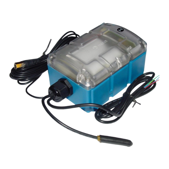
- Page 16 4.5 Overview Overview myDatalogNANOamr 1 Antenna connector 3 Sensor cable with open ends (channel 1 and channel 2) 2 Sealed sensor cable (channel 3 and 4 Housing cover channel 4) 4.6 Intended use The portable measurement instrument is used to record meter readings. The device can operate without mains power.
- Page 17 The device is equipped with an integrated SIM chip. 4.8 Device labelling The specifications in this user manual apply exclusively to the myDatalogNANOamr device type. The type plate is located on the top of the device and includes the following specifications:...
- Page 18 23) via the solenoid contact so that the amended configuration is transferred to the myDatalogNANOamr . During this process, all of the data that has not yet been transferred to the myDataweb server is transferred. The cables and antenna can be removed as soon as the GPRS connection has been deactivated - indicated by the status LED going out (see "Status LED"...
- Page 19 Chapter 4 General specifications In addition, the operator must comply with the local legal requirements for the safety of the personnel (accident prevention measures) the safety of the equipment (protective equipment and maintenance) the product disposal (waste disposal law) the material disposal (waste disposal law) the cleaning (cleaning agents and disposal) and the environmental protection amendments.
- Page 21 Functional principle of recording meter readings Meter with pulse output (switch contact) 2 myDatalogNANOamr with integrated managed service SIM chip including data transmission 3 Client who access the WebApp via a smartphone 4 myDataweb server to which the data is transferred 5 Client that accesses the interface of the myDataweb server via the web browser 6 Customer-specific server that provides clients with their own interface.
- Page 22 Functions and components provided by myDatanet : myDatalogNANOamr The myDatalogNANOamr is a compact portable device for connecting the meters (IN1-4) to the myDataweb server (GPRS). Managed Service: Managed Service is the basis for operating your devices and provides you with a wide range of services.
- Page 23 5.2 Selection of the GSM network The GSM network to which the device should register must be selected, as the myDatalogNANOamr is equipped with a SIM chip that provides a mobile connection via a variety of international service providers (see www.microtronics.at/footprint ).
- Page 24 53) 1. The myDatalogNANOamr checks whether any errors occurred during the last login attempt. No errors: The myDatalogNANOamr logs into the same GSM network that was also used last time. Error: Continue with the next step Note: A transmission error is not the same as an error that occurs when logging into the GSM network.
- Page 25 Antenna 900 FME (206.801) BP434RLC (206.725) The battery pack (BP434RLC ) was already inserted in the myDatalogNANOamr during production. Additional accessories such as internal expansions, assembly sets, antennas, accu or battery pack, sensors, power supply, charging devices, etc., depending on the order. Please check these against the delivery slip.
- Page 26 Support & Service Centre (see "Contact information" on page 125). The return shipment of the myDatalogNANOamr must occur in the original packaging and with freight and insur- ance paid to Microtronics Engineering GmbH (see "Contact information" on page 125). Insufficiently cleared return shipments will otherwise not be accepted! Rev.
- Page 27 7.1 Dimensions Dimensions: Width and height Dimensions: Depth 7.2 Installing the myDatalogNANOamr Important note: Ensure the installation is completed properly. Comply with the existing legal and/or operational directives. Improper handling can cause injuries and/or damage to the devices.
- Page 28 The installation site must be selected according to specific criteria. The following conditions must be avoided in any case: Direct sunlight Objects that radiate intense heat (maximum ambient temperature: -20...+60°C) Objects with a strong electromagnetic field (frequency converter or similar) Corrosive chemicals or gases Mechanical impacts Direct installation on foot or road ways...
- Page 29 If you want to use the tapping screws (4) included in the equipment set, first of all insert the supplied wall plugs into each of the four drill holes before screwing the myDatalogNANOamr with the attached assembly loop (3) to the wall (see "Step 2 of the wall mounting" on page 28).
- Page 30 "Step 1 of the top-hat rail assembly " on page 30). 2. Place the assembly loop (3) onto the top edge of the top-hat rail. When turned slightly around the horizontal axis of the myDatalogNANOamr with the assembly loop (3) attached, the Rev. 01...
- Page 31 The optional "Pipe mounting kit for myDatanet housing 86x126 (206.660)" equipment is required for the pipe assembly. Step 1 of the pipe assembly Step 2 of the pipe assembly 1 myDatalogNANOamr 3 Assembly loop (included in the scope of delivery of 206.660) 2 Delta PT M3.5x8 Torx 15 (included in the 4 Cable binder (included in the scope of scope of delivery of 206.660)
- Page 32 86x126 (206.660)" equipment set to the myDatalogNANOamr (see "Step 1 of the pipe assembly " on page 31). 2. Position the myDatalogNANOamr with the attached assembly loop (3) on the pipe and use the supplied cable binders (4) to secure the myDatalogNANOamr (see "Step 2 of the pipe assembly"...
- Page 33 Run all data cables so that they do not pose a trip hazard and ensure that cables do not have any sharp bends. The myDatalogNANOamr must not be operated in the field with the lid open. Connection of the sensors and power supply 1 Antenna connector 3 Sensor cable with open ends (channel 1 and...
- Page 34 LED should then start to flicker (see "Status LED" on page 46), indicating that a connection is being established. Note: If the myDatalogNANOamr is still in transport mode, the transport lock is deactivated by the initiation of ALOHA transmission mode and the device starts to operate in accordance with the configuration.
- Page 35 . In the event of a low radio signal strength, you can use the Flat antenna Smart Disc FME-F (206.814). If the length of the 3m antenna cable of the myDatalogNANOamr is not long enough, you can use a 5m Extension cable for Antenna 900 FME (206.805).
- Page 36 1. If you need an antenna extension, connect this to the antenna first. 2. Connect the antenna extension or antenna directly to the antenna cable of the myDatalogNANOamr (see "Overview" on page 16). Important note: Do not apply too much force when tightening the antenna. Do not use any tools to tighten the antenna or antenna extension;...
- Page 37 Ex approved will render this approval invalid) 7.4.3.3 Procedure for determining the optimum position of the antenna 1. Install the myDatalogNANOamr as described in chapter "Installing the myDatalogNANOamr " on page 27. During this process, also observe the notes regarding the influences on the signal quality (see "Influences on the signal quality"...
- Page 38 interval dependent on the selected "Reader type" (see "Config" on page 49) for a sample time that is also dependent on the selected "Reader type". The sample interval is 15,6ms for all "Reader types" for which the signal detection is greater or equal to 64ms. For all of the other "Reader types", the sample interval is 1ms.
- Page 39 Chapter 7 Installation Note: It must be noted that if the transport lock is activated, the myDatalogNANOamr uses a certain, albeit low, amount of energy even during storage. This means that if a device has already been stored for a prolonged period that the operating times in the following table might not be able to achieved anymore.
- Page 41 8.3 Placing the system into operation Note: It is recommended that the myDatalogNANOamr is first placed into operation in the office before mounting the device permanently at the place of use. During this process, you should set a site for the later operation on the myDataweb server (see "myDatanet Server Manual"...
- Page 42 The myDatalogNANOamr must be in ALOHA transmission mode for this purpose. 10. If you intend to install the myDatalogNANOamr in a shaft, you must check that the device can also establish a GPRS connection in the final installation position when the shaft lid is closed before you leave the place of use.
- Page 43 2. Configure the created site according to your requirements (see "Site configuration" on page 47). 3. Link the myDatalogNANOamr with the created site (see "Site" on page 47). 4. Initiate the ALOHA transmission mode (see "ALOHA transmission mode" on page 23) so that the configuration of the site is transferred to the myDatalogNANOamr .
- Page 44 Note: Additional explanation about evaluating the "GSM level": "GSM level" >-64dBm -64 to -73dBm -74 to -83dBm -84 to -93dBm -94 to -107dBm <= -108dBm Rev. 01...
- Page 45 Chapter 9 User interfaces Chapter 9 User interfaces The configuration of the myDatalogNANOamr is carried out via the web interface on the myDataweb server (see "User interface on the myDataweb-Server" on page 47), which your responsible sales partner will provide to you.
- Page 46 Solution/cause code Transport lock (GPRS OFF, measurement If the ALOHA transmission mode is OFF) initiated by the solenoid switch, the myDatalogNANOamr switches back into "RUN" mode (GPRS ON, measurement ON). Last connection OK Last transmission faulty Try again later Standby (GPRS ON, measurement OFF) see "transport lock"...
- Page 47 Chapter 9 User interfaces 9.2 User interface on the myDataweb-Server 9.2.1 Site configuration Note: Several of the configuration fields in the following sub chapters may possibly be hidden depending on the respective user level. In this case, please contact the myDataweb-Server administrator. Click on the name of the site in the list of sites to get to the input screen for configuring the site (see "myDatanet Server Manual"...
- Page 48 9.2.1.3 Measurement channels 9.2.1.3.1 Basis Title 1-4 Freely selectable channel title for the meter inputs Mode Basic settings for the measurement channel Measurement channel deactivated Cnt.Inf Infinite counter Impulse Metered measurand of a pulse in the "Imp. unit" Imp.unit String that the WebApp displays as the measuring unit when specifying the pulse value (see "Configuring the measurement channels"...
- Page 49 Chapter 9 User interfaces 9.2.1.3.2 Config Reader type Selection of the reader type Elster Grey Snapfit (4 ms) Elster reader Elster Black Snapfit (4 ms) Minimum signal length for the signal detection: 4 ms sample interval: 1ms Elster T. PROBE (4 ms) sample time: 30µs Elster LRP (4 ms) Elster Q4000 (4 ms) Elster HRP (4 ms)
- Page 50 Aquamaster (8 ms) Aquamaster reader Minimum signal length for the signal detection: 8 ms sample interval: 1ms sample time: 30µs slow (200 ms) Universal setting for long pulses: Minimum signal length for the signal detection: 200 ms sample interval: 15,6ms sample time: 30µs medium (64 ms) Universal setting for medium pulses: Minimum signal length for the signal detection: 64 ms sample interval: 15,6ms...
- Page 51 Chapter 9 User interfaces Mode Possible calculation modes for the calculated channels Calculated channel deactivated Table Defines the lower scale end of the pointer instruments Defines the upper scale end of the pointer instruments Unit String, which is used as the measurement unit by all of the server display elements Decimal Number of decimal places that are used by all of the server display...
- Page 52 9.2.1.4.3 Alarm Note: The alarm levels for calculated channels can only be evaluated once the device has transmitted the measurement data to the myDataweb server. Alarm low An alarm is initiated if the measurement value drops to or below this value. Alarm high An alarm is initiated if the measurement value meets or exceeds this value.
- Page 53 Chapter 9 User interfaces 9.2.1.7 Basic setting Connection type Interval The device registers in the transmission cycle. Aloha/Wakeup duration Aloha/Wakeup duration connection Transmission cycle Time between transmissions Transmission time Time at which the device establishes a connection to the server regardless of the transmission cycle.
- Page 54 FTP export FTP export deactivated profile "Name of an List with the FTP export profiles that were created on the Server FTP export (for creating an FTP export profile, see "myDatanet Server profile" Manual" 805002). Settings of the shows an overview of the most important parameters of the selected FTP export selected profile profile FTP directory...
- Page 55 Chapter 9 User interfaces Last In each case, the last time stamp of the affected operation connection Last wakeup Last disconnection Last transmission error Last Aloha connection Firmware Firmware update is deactivated update As soon as a new version of the selected firmware type is available, this is installed immediately.
- Page 56 9.2.2.4 GPRS SIM tariff Selected SIM tariff Rev. 01...
- Page 57 Chapter 10 myDataweb server Chapter 10 myDataweb server Note: All of the screenshots show version 38.1 of the myDataweb server using the standard colour scheme. Newer versions may include minor changes to the appearance of the server. 10.1 Overview Overview of the myDataweb server 1 Tabs to switch between the individual server 5 Logout the active user areas...
- Page 58 10.2 "Customer" area Overview of the "Customer" area 1 Current "Overview map" on which the sites can be placed 2 Adds a new customer 3 Opens the input screen for configuring the customer 4 Deletes the customer 5 Comment that can be entered in the configuration of the customer 6 If a default report was defined, the default report is accessed by clicking on the name of the customer.
- Page 59 Chapter 10 myDataweb server 10.3 "Site" area at customer level Overview of the "Sites" area at customer level 1 Symbol via which an image file can be loaded on to the server as a "Map" To remove the "Map" again, open the upload dialogue again and click on "Submit" without selecting an image file beforehand.
- Page 60 1 Menu item to call up the list of customers 3 List of available customers 2 Creating a new customer 3. Click on the "Sites" menu item of the myDataweb server to call up the list of available sites. Create a new "myDatalogNANOamr " type site. Rev. 01...
- Page 61 2 Creating a new site 4. Link the site with the myDatalogNANOamr by selecting the serial number. If the serial number of your device is not included in the list, you must first of all assign the device to the customer (see "Assigning a device to the customer"...
- Page 62 1. Log in via the web interface on the myDataweb server. You will receive the web address from your responsible sales partner. Login form of the myDataweb server 2. Click on the "Pool and Aloha" menu item of the myDataweb server to access the list of devices that are in ALOHA transmission mode.
- Page 63 Chapter 10 myDataweb server 4. Use the filter to find the required device in the list of measurement instruments. Click on the symbol to open the dialogue to select the customer (see "Assigning a device to the customer" on page 62) and assign the device to the selected customer. Rev.
- Page 65 Chapter 11 WebApp 11.1 General The WebApp is not a native application that you have to install on your smartphone, it is instead an optimised web interface of the myDataweb server for the displays of these devices. You therefore only have to access the web interface of the myDataweb server via the browser of the smartphone. However, this optimised interface is only displayed if a Level 1 or 2 user has logged in.
- Page 66 Login dialogue (iPhone) After you have entered your login details, you can access the list of sites Note: The "Direct login" link can only be created from the list of sites. Rev. 01...
- Page 67 11.2.1 iOS (iPhone) Select the symbol to open the submenu. List of sites (iOS) Submenu for creating a link Use the "Add to home screen" button to add a "Direct login" link as a symbol on your "Home screen" or use the "Add bookmark" button to bookmark your "Direct login" link. Rev.
- Page 68 11.2.2 Android 2.2 Select the submenu button to access the browser's basic menu and then select the symbol to expand the menu. List of sites (Android) Submenu for creating a link Use the "Add shortcut to home" button to add a "Direct login" link as a symbol on your "Home screen".
- Page 69 11.3 List of sites You will have access to the list of sites once you have logged in via the login dialogue. List of sites sorted according to distance List of sites sorted according to title 1 Text input field to filter the list of sites 5 Distance and direction to the site 2 Indicates that the list of sites is sorted 6 Title of the measurement channels...
- Page 70 List of sites: devices in ALOHA transmission mode 1 Device offline 2 Device in ALOHA transmission mode 11.3.1 Determining the position of the site The position of the site must be determined to indicate the distance to the site in the list of sites. If you are at the site, you can use the GPS receiver of your smartphone to assign your current position to the site via the WebApp .
- Page 71 11.4 Site info screen The site info screen is accessed by clicking on the site in the list of sites (see "List of sites" on page 69). In this case, the background colour will indicate the connection status (green for ALOHA transmission mode, blue for offline) of the device connected to the site.
- Page 72 Editing the comment 1 Back to the site info screen without saving 3 Input field for a comment about the site 2 Title of the site 4 Save change and go back to the site info screen 11.4.2 Configuring the measurement channels To configure the measurement channel, click on the relevant entry in the info screen of the site (see "Site info screen"...
- Page 73 (see "Measurement channels" on page 48). Can only be edited via the standard web interface (see "Measurement channels" on page 48) The input fields can only be edited when the myDatalogNANOamr is in ALOHA transmission mode. 11.4.2.1 User level 1 Users of authorisation level 1 can only edit the pulse value and meter reading.
- Page 74 1 Input field to change the meter reading (can 3 Button for accepting the configuration only be edited when the measurement changes channel is activated) 2 Metered measurand of a pulse in the "Imp. unit" 11.4.2.2 User level 2 Users of authorization level 2 can edit the reader type and title of the measurement channel in addition to the pulse value and the meter reading.
- Page 75 Chapter 12 XML interface Chapter 12 XML interface Important note: The relevant licences are required on the myDataweb server to use the XML interface. If the licence is not available for the XML export, the following message is displayed for every request: " ".
-
Page 76: Table Of Contents
Generally applicable table identifiers Identifier Description mydatalognanoamrid Site configuration (see "mydatalognanoamrid" on page 76) geraetid Devices (see "geraetid" on page 83) bookingline Connection list (see "bookingline (read only)" on page 85) kundeid Customers (see "kundeid" on page 85) Device-specific table identifier Identifier Allocation Description... - Page 77 Chapter 12 XML interface name Site designation (not relevant for the device or data assignment)[2-50 characters] timezone Regional settings (not relevant for raw measurement data as this is stored in the UTC) Value Explanation 99.00 The regional setting for the site is adopted from the global server setting. -12.00 UTC -12 hours +14.00...
- Page 78 transfer_alerts Alarm in the event that the device does not respond for longer than the set transmission cycles Value Explanation No alarm settings standard (>2x transmission cycles) immediately (>1x transmission cycle) medium (>5x transmission cycles) long (>10x transmission cycles) extra long (>20x transmission cycles) max_transfer_volume Settings for the transfer volume alarm Value...
- Page 79 Chapter 12 XML interface loc_alarm_rad This is a "Ghost" field, the content of which always corresponds to that of the "loc_alarm_rad_ mode" field. view Selection of the report that is loaded by clicking on the device link in the maps Value Explanation *OFF*...
- Page 80 wire_color1 - wire_color4 Specifies the colours of the pair of wires for the meter input(read only) Rev. 01...
- Page 81 Chapter 12 XML interface reader_type1 - reader_type4 Selection of the reader type Important note: This parameter only specifies the selection for the display on the myDataweb server. To function correctly, the minimum signal length for the signal detection (time specification provided in brackets in the following table) in the "mydatalognanoamr_channel"...
- Page 82 ftpexportprofile Selection of the FTP export profile Value Explanation FTP export deactivated "id" To obtain the "id", open the configuration of the required FTP export profile (see myDatanet Server Manual805002) and take the ID from the address line of the browser (e.g.
- Page 83 Chapter 12 XML interface title7 Freely selectable channel title for the battery voltage units7 Battery voltage: String, which is used as the measurement unit by all of the server display elements The following parameters apply to the "Calculated channels" (see "Calculated channels" on page title60 - title64 Freely selectable channel title for the calculated channels [0-16 characters] units60 - units64...
- Page 84 devclass Device class The instrument class of the site and instrument must match for an instrument to be able to be connected to a site. telno Telephone number of the SIM card. The control SMS messages (e.g. wakeup) are sent to this number.
- Page 85 Chapter 12 XML interface fw_release_type Settings for the firmware type Value Explanation Released: Only firmware versions that have successfully undergone internal and field testing are installed (this practically eliminates malfunctions). Release candidate: Only firmware versions that have successfully undergone internal testing are installed (malfunctions cannot be excluded). Beta release: Even firmware versions that have not successfully undergone all of the internal tests are installed (malfunctions may occur).
- Page 86 strasse Street [0-50 characters] plzort Postcode and town [0-50 characters] comment Comment on the customer. This is displayed in the customer overview below the name. erp_code The ERP code is designed to simplify and speed up the charging process. All costs that are, for example, incurred through SMS or calls are charged directly to this ERP code.
-
Page 87: Mydatalognanoamr_Data
12.2.2 Device-specific table identifier 12.2.2.1 mydatalognanoamr_data This table includes the measurement data of the myDatalogNANOamr (see "Measurement channels" on page 48, "Internal channels" on page 52 and "Calculated channels" on page 50). context Unique data record number of the site (read only) - Page 88 Battery voltage [%] (calculated based on the battery voltage in Volt) 12.2.2.2 mydatalognanoamr_channel This table includes the configuration of the meter inputs (see "Measurement channels" on page 48) that is transferred to the myDatalogNANOamr . context Unique data record number of the site (read only)
-
Page 89: Mydatalognanoamr_Log
Parameter for the log entry 12.2.2.4 mydatalognanoamr_user1 This table includes the remaining configuration that is specific to the myDatalogNANOamr device class and is not included in the "mydatalognanoamr_channel" table (see "mydatalognanoamr_ channel" on page 88). The configurations from the "mydatalognanoamr_user1" table are transferred to the myDatalogNANOamr . - Page 90 context Unique data record number of the site (read only) measure_mode Operating type Value Explanation HOLD Measurement: OFF, transmission: ON Measurement: ON, transmission: ON Measurement: OFF, transmission: OFF OFFLINE Measurement: ON, transmission: OFF Reserved for internal use record_interval Time between measurements (00:00 same as record interval) [1...1090min] transfer_interval Time between transmissions [00:10...168:00 hh:mm] pos_cycle...
-
Page 91: Mydatalognanoamr_State
Chapter 12 XML interface 12.2.2.5 mydatalognanoamr_state This table contains the device status at the time of the last transmission. Note: As, depending on the system, the GSM field strength and battery voltage are measured more frequently than the recording is completed, the values included in this table do not always correspond exactly to the last entry in the "mydatalognanoamr_data"... -
Page 92: Mydatalognanoamr_Set
>31,000 Position determined by the GPS receiver The myDatalogNANOamr does not include a GPS receiver. Information about the five GSM cells in the receiving range that were used to determine the position gsm_mcc_0 - gsm_mcc_4 MCC (mobile country code) of the GSM cell... - Page 93 This means that the meter reading will only be reset and the content of the field will only be deleted during the next connection of the myDatalogNANOamr with the myDataweb server. It is therefore advisable to only reset the counters when the myDatalogNANOamr is online (is in ALOHA transmission mode).
- Page 94 You can access a list of all the types of sites that are supported by the myDataweb server by specifying the xPath query SiteTypes https://server-URL:8080/SiteTypes?user=u1&password=p1 Result: <Result> <SiteType class="6000" title="myDatalogNanoAMR"> FFFF6000 </SiteType> </Result> 12.3.1.1.3 Filter conditions The filter condition is always within square brackets and comprises expressions that can be linked by keywords such as .
- Page 95 Time stamp within single inverted commas ' Formats (comma, date format, etc.) are adopted from the user or server settings. 12.3.1.1.3.1 Example: The configuration of all sites of the type myDatalogNANOamr is displayed if no filter conditions are provided. https://server-URL:8080/mydatalognanoamrid?user=u1&password=p1 Rev. 01...
- Page 96 (e.g. FFFF0005 for the table identifier). geraetid 12.3.1.1.4.1 Example The following example provides the names of all sites of the type myDatalogNANOamr https://server-URL:8080/mydatalognanoamrid/(name)?user=u1&password=p1 Rev. 01...
- Page 97 [last()-1] Last data record (with the latest time stamp) Other index specifications, such as are invalid. [last()-2] 12.3.1.1.5.1 Example The following example provides the first data record of a myDatalogNANOamr type site that is called "Site1". https://server-URL:8080/mydatalognanoamrid[name='Site1']/mydatalognanoamr_data[0] ?user=u1&password=p1 Result: <Result>...
- Page 98 Specifies that the data from the measurement data table should be queried. Specifies that the first data record (with the oldest time stamp) should be queried. The following example supplies the last data record of a myDatalogNANOamr type site that is connected to the device with serial number "010146AF251D0BA9".
- Page 99 Chapter 12 XML interface [last()-1] Specifies that the last data record (with the latest time stamp) should be queried. 12.3.1.2 Data record compression Data record compression can be activated via the optional setting. This means that all period=... of the data records within the specified period are compressed with the per field adjustable calculation method.
- Page 100 Note: The user must have the relevant rights to modify the data (see tbd). 12.3.1.3.1 Example The following example sets the "Firmware update" to "ON" and the "Firmware type" to "Release candidate" for all of the devices that are compatible with the myDatalogNANOamr type site. https://server-URL:8080/geraetid[devclass=6000]?user=u1&password=p1 &$fw_update=1&$fw_release_type=1 Result: <Result>...
- Page 101 Specifies that the entry point for the request is the device table. [devclass=6000] Specifies that the action should apply to all of the devices that are compatible with the myDatalogNANOamr type site. $fw_update=1 Specifies that the "Firmware update" should be set to "On".
- Page 102 The data fields have the following attributes: Attribute Explanation title Title of the data field (for measurement data this is dependent on the site settings) units Units of the data field for measurement data (dependent on the site settings) calc OPTIONAL Is only displayed if it is a channel that has been calculated by the sever 12.3.2.1 Example:...
- Page 103 Chapter 12 XML interface A HTTP POST command can, for example, be executed with the freely available "Wget" command line tool (http://www.gnu.org/software/wget/). 12.4.2 Configuration of a HTTP-POST command Important note: The transmission of XML files to the server is completed via the HTTP server (standard port 80) and not the xPath server (standard port 8080).
- Page 104 12.4.3 Structure of the XML file 12.4.3.1 Changing existing data If an existing data record has to be changed, the unique identification number of the data record that is going be changed must be specified as the attribute (e.g. ). The id ="F000002200000282"...
- Page 105 Chapter 12 XML interface Site to which the data record should be linked: <Result> <mydatalognanoamrid id="A1526911CF9CCAA0" stamp="13.2.2013 10:00:54" > <tag> FFFF6000 </tag> <name title="Name"> Site1 </name> </mydatalognanoamrid> </Result> XML file: <?xml version="1.0"?> <Result> <mydatalognanoamr_data id="0" stamp="16.1.2013 09:00"> <ch1>0.0000</ch1> <tag>00006000</tag> <context>A1526911CF9CCAA0</context> </mydatalognanoamr_data> </Result>...
- Page 107 Check all of the connections for leaks or corrosion on a regular basis. Check all of the cables for mechanical damage at regular intervals. Clean the myDatalogNANOamr with a soft, moist cloth. Use a mild cleaning agent, if necessary. 13.2 Replacing the battery pack...
- Page 108 23) and then check again that all of the relevant data has been transferred. 2. Remove the four screws that secure the housing cover and open the myDatalogNANOamr . 3. Disconnect the connector of the battery pack from the device's supply connector.
- Page 109 Chapter 13 Maintenance 4. Rotate the battery pack to the left (see "Removing the battery pack - step 1" on page 109) so that it slips out of the retaining bracket on the opposite side to the connection cable. You can then simply remove it in an upwards direction (see "Removing the battery pack - step 2"...
- Page 110 5. Complete the steps in reverse order to insert the new battery pack. During this process, ensure that the connection cable of the negative pin of the battery pack (black cable) is between the battery pack and retaining bracket. 6. Reconnect the connector of the battery pack to the supply connector of the device. Just like when the connection was disconnected, avoid applying excessive force and insert the con- nector of the battery pack as straight as possible into the supply connector.
- Page 111 Dispose of the device in accordance with the locally valid environmental regulations for electronic products. Rechargeable batteries and/or battery packs may not remain in the myDatalogNANOamr after dis- charging. Ensure that the used rechargeable batteries and/or battery packs are disposed of in an environmentally proper way.
- Page 113 Chapter 15 Troubleshooting and repair Chapter 15 Troubleshooting and repair 15.1 General problems Problem Cause/solution Device does not The capacity of the battery pack is depleted. Instructions on replacing the respond (status battery pack are provided in the chapter "Replacing the battery pack" on page LED always off) 107.
- Page 114 15.2 Log entries and error codes Log entry Parameter Description Code Plain text Code Plain text 1020 ERROR SOD Internal system error There may be a hardware problem if this error is included in the device log several times with the same parameter code. Contact the manufacturer in this case (see "Contact information"...
- Page 115 Check the connection between the device and the sensor HOLD Standby (GPRS ON, measurement OFF) If the ALOHA transmission mode is initiated, the myDatalogNANOamr switches back into "RUN" mode (GPRS ON, measurement ON). TRANSPORT Transport lock (GPRS OFF, measurement OFF) see "Standby"...
- Page 116 Log entry Parameter Description Code Plain text Code Plain text 1600 STATE IP ERROR No myDataweb server available (1/2) (1/2) Check whether port 51241 is enabled on the myDataweb server. Try again later SIM CARD ERROR Faulty SIM chip Contact support. 2000 MODULE ERR Reserved for extensions 3000...
- Page 117 Try again later BEARER NO -992 --- No answer ANSWER Try again later Check whether the device is in the coverage area (www.microtronics.at/footprint). BEARER NO -991 --- No carrier CARRIER Try again later Check whether the device is in the coverage area (www.microtronics.at/footprint).
- Page 118 1200 BEARER GPRS STOP -976 --- Invalid handling BAD HDL Internal error BEARER GPRS STOP -975 --- Internal error UNKNOWN 1200 NETLOCK FAILURE -970 --- Error when selecting the network Check whether the device is in the coverage area (www.microtronics.at/footprint). Rev. 01...
- Page 119 Try to improve the position of the antenna. Check whether the device is in the coverage area (www.microtronics.at/footprint). TCP channel error (1/2) 1200 CHANNEL ABORTED -965 --- An attempt is being made to write to/read a TCP client that is no longer available.
- Page 120 Log entry Parameter Description Code Plain text Code Plain text TCP channel error (2/2) 1200 CHANNEL REFUSED -955 --- The TCP connection has been refused by the server. Try again later CHANNEL HOST -954 --- No route to the host. UNREACHABLE Try again later CHANNEL NETWORK...
- Page 121 Chapter 16 Spare parts and accessories Chapter 16 Spare parts and accessories 16.1 Assembly sets Description Quantity Order number Universal bracket for housing myDatanet 86x126 206.640 DIN rail mounting set for myDatanet housing 86x126 206.634 Pipe mounting kit for myDatanet housing 86x126 206.660 16.2 Antennas Description...
- Page 123 Chapter 17 Document history Chapter 17 Document history Rev. Date Changes 26.04.2013 First version Rev. 01...
- Page 125 Chapter 18 Contact information Chapter 18 Contact information Support & Service: Microtronics Engineering GmbH Hauptstrasse 7 3244 Ruprechtshofen Austria, Europe Tel. +43 (0)2756 7718023 support@microtronics.at www.microtronics.at Microtronics Engineering GmbH Microtronics Engineering GmbH (Headquarter) Windthorststrasse 5 Hauptstrasse 7 63179 Obertshausen 3244 Ruprechtshofen...
Need help?
Do you have a question about the myDatalogNANOamr and is the answer not in the manual?
Questions and answers