
Related Manuals for Microtronics myDatalogEx


Summary of Contents for Microtronics myDatalogEx
-
Page 1: Cover
User manual myDatalogEx Cover Valid from: Firmware version: 01v018 App. version: 01v000 Server version: 49v011 Hardware version: 2.0 301022 | Rev.05... -
Page 3: Table Of Contents
Chapter 1 Table of contents Chapter 1 Table of contents Cover Chapter 1 Table of contents Chapter 2 Declaration of conformity Chapter 3 Ex certification Chapter 4 Specifications Chapter 5 General specifications 5.1 Translation 5.2 Copyright 5.3 General descriptive names 5.4 Ex protection 5.5 Safety instructions 5.5.1 Use of the hazard warnings... - Page 4 9.4 Placing the system into operation 9.4.1 Using the mobile connection (2G/3G) and the myDatanet server 9.5 Testing communication with the device 9.5.1 Testing communication between the myDatalogEx and the myDatanet server (mobile connection) Chapter 10 User interfaces Rev. 05...
- Page 5 Chapter 1 Table of contents 10.1 User interface on the myDatalogEx 10.1.1 Operating elements 10.1.1.1 Reed switch 10.1.1.2 Display 10.2 User interface on the myDatanet server 10.2.1 Site configuration 10.2.1.1 Setup data 10.2.2 Device configuration 10.2.2.1 Comments 10.2.2.2 Measurement instrument 10.2.2.3 GPRS...
- Page 6 15.3.2 Evaluating the device log using DeviceConfig Chapter 16 Spare parts and accessories 16.1 Assembly sets 16.2 Antennas 16.3 Cable 16.4 Other accessories Chapter 17 Document history Chapter 18 Glossary Chapter 19 Contact information Rev. 05...
-
Page 7: Chapter 2 Declaration Of Conformity
Chapter 2 Declaration of conformity Chapter 2 Declaration of conformity Rev. 05... -
Page 9: Chapter 3 Ex Certification
Chapter 3 Ex certification Chapter 3 Ex certification Rev. 05... - Page 10 Rev. 05...
- Page 11 Chapter 3 Ex certification Rev. 05...
- Page 12 Rev. 05...
-
Page 13: Chapter 4 Specifications
Chapter 4 Specifications Chapter 4 Specifications Voltage supply Battery: 2 x Li-SOCl2 cells with a total of 25,74Ah Enclosure Material: Noryl GTX 973 / PC (enclosure/cover) Weight: 730g Protection class: IP67 Dimensions (WHD): 106 x 169 x 61mm (with protective armour) Ex certification II 2G Ex ib IIB T3 Gb Operating temperature... - Page 14 Integrated SIM chip Monthly data volume Approx. tbd at 5min. measurement interval and 12h transmission interval Device operating time Up to 24 months battery life at 5min. measurement interval, 1sec. heat up and 12h transmission interval Rev. 05...
-
Page 15: Chapter 5 General Specifications
Chapter 5 General specifications Chapter 5 General specifications The information in this manual has been compiled with great care and to the best of our knowledge. The manufacturer, however, assumes no liability for any incorrect specifications that may be provided in this manual. -
Page 16: Ex Protection
2 Sensor approved for the Ex zone 5.5 Safety instructions For the connection, commissioning and operation of the myDatalogEx , the following information and higher legal regulations of the country (e.g. ÖVE), such as valid EX regulations as well as the applicable safety and accident prevention regulations for the respective application case must be observed. -
Page 17: Use Of The Hazard Warnings
Chapter 5 General specifications Important note: The manufacturer's products that are designed for outdoor use include extensive protection against moisture and dust penetration. 5.5.1 Use of the hazard warnings DANGER: Indicates a potential or threatening hazardous situation that will result in death or serious injuries if not avoided. -
Page 18: Safety And Precautionary Measures For The Gsm/Gprs Modem Installation
5.5.3.1 Safety and precautionary measures for the GSM/GPRS modem installation This device must only be installed by a trained technician who applies the recognised installation practices for a wireless frequency transmitter including the correct grounding of external antennas. The device must not be operated in hospitals and/or in the vicinity of medical equipment such as heart pacemakers or hearing aids. -
Page 19: Overview
Chapter 5 General specifications 5.6 Overview Front of the myDatalogEx Bottom of the myDatalogEx (view without protective armour) (view without protective armour) 1 Display 3 Antenna connector 2 Sensor connector Rev. 05... -
Page 20: Block Diagram
A Managed Service contract with Microtronics Engineering GmbH is required for use of the mobile data transmission (see www.microtronics.com/managedservice). This includes the provisioning of the mobile communications connection via the network of the service provider included in the above-mentioned list. -
Page 21: General Product Information
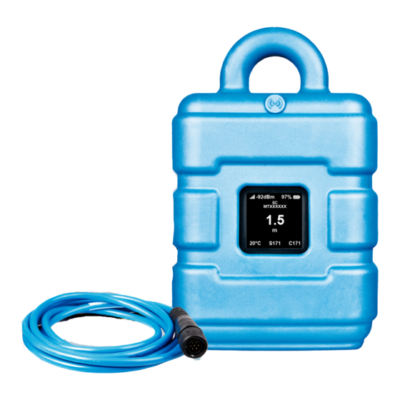
("myDatanet Server Manual " 805002). The myDatalogEx has a 1,5" OLED display to show the current measurement value at the universal input (incl. unit) and a variety of status information (e.g. remaining days until the battery will next be replaced in the device). -
Page 22: Installation Of Spare And Wear Parts
5.11 Storage of the product To store the myDatalogEx , activate the transport mode in the in the input screen of the myDatanet server for configuring the device. Then activate the setup mode (see "Setup mode" on page 27) via the reed switch so that the amended configuration is transferred to the myDatalogEx . -
Page 23: Disclaimer
For safety and warranty reasons, all internal work on the instruments beyond from that involved in normal installation and connection, must be carried out only by qualified Microtronics personnel or persons or companies authorised by Microtronics . -
Page 24: Personnel Requirements
Before commissioning, the operator must ensure that the installation and commissioning – provided these were performed by the operator himself – are in compliance with the local regulations. 5.15 Personnel requirements Installation, commissioning and maintenance may only be completed by personnel who meet the following conditions: Qualified specialist personnel with the relevant training Authorised by the facility operator... -
Page 25: Chapter 6 Functional Principle
In the graphic below, all of the components that are part of the myDatanet are illustrated in grey. All other components must be provided/created by the customer. Functional principle myDatalogEx with integrated managed service SIM chip myDatanet server to which the data is transferred Client that accesses the interface of the myDatanet server via the web browser Customer-specific server that provides clients with their own interface. -
Page 26: Functionality Of The Internal Data Memory
The internal data memory of the myDatalogEx is designed as a circular buffer with 8 sectors. If the maximum number of data records (66.856 ) is achieved, the sector with the oldest data is deleted fully before new data can be saved in this sector again. -
Page 27: Procedure In Case Of Connection Aborts
Setup mode is an operating mode specifically developed for testing the GSM signal quality in the final installation position of the myDatalogEx . Setup mode is activated by pressing the reed switch for at least three seconds. (see "Reed switch" on page 51). A connection to the myDatanet server is thus initially established to inform it about setup mode being activated. - Page 28 1 MDN Magnet (206.803) 2 myDatalogEx The first of the two connections to the server are completed as part of setup mode. The connection establishment and then the data synchronisation are indicated on the display of the device by means of the relevant graphics.
- Page 29 "Setup" inscription. The myDatalogEx terminates the connection to the server and starts to measure the GSM level for a period of up to 3min. . The speech bubble with the "Setup" inscription continues to be displayed during this process.
- Page 30 5. Either wait until the speech bubble is hidden again (setup mode completed successfully) or until the background colour of the speech bubble changes from white to red (problem detected). In both cases, this can take up to 8min. . If a problem is detected, it is advisable to improve the position of the antenna (see "Optimum antenna positioning for assembly in a shaft"...
-
Page 31: Automatic Selection Of The Gsm Network
6.4 Automatic selection of the GSM network The GSM network to which the device should register must be selected, as the myDatalogEx is equipped with a SIM chip that provides a mobile connection via a variety of international service providers (see www.microtronics.com/footprint ). -
Page 33: Chapter 7 Storage, Delivery And Transport
Store the device so that it is protected against corrosive or organic solvent vapours, radioactive emissions as well as strong electromagnetic radiation. 7.4 Transport Protect the myDatalogEx against heavy shocks, bumps, impacts or vibrations. The original packaging must always be used for transport. Rev. 05... -
Page 34: Return
An RMA number is mandatory for any returns and can be obtained from the Support & Service Centre (see "Contact information" on page 83). The return shipment of the myDatalogEx must occur in the original packaging and with freight and insurance paid to Microtronics Engineering GmbH (see "Contact information"... -
Page 35: Chapter 8 Installation
Chapter 8 Installation Chapter 8 Installation Important note: To prevent any damage to the device, the work described in this section of the instructions must only be performed by qualified personnel. 8.1 Dimensions Dimensions: Height Dimensions: Width and depth (view with protective armour) (view with protective armour) Rev. -
Page 36: Installing The Mydatalogex
Improper handling can cause injuries and/or damage to the devices. The myDatalogEx must not be operated in the field without a protective armour. Due to the electrostatic effects, the protective armour must not be rubbed with cloths in the Ex zone. -
Page 37: Suspended Installation
1. Attach the Multi band antenna with bracket (300787) on the rear side of the myDatalogEx . 2. Use the Niro shackle (206.325), to attach the myDatalogEx to a rung of the manhole ladder or a similar fastening point in accordance with the figure "Detailed view of a suspended installation" on page 37. -
Page 38: Electrical Installation
"Detailed view of a suspended installation" on page 37 . Important note: The sensor connection of the myDatalogEx is not designed to carry heavy loads. For this reason, a clamp must be used in order to fasten the sensor cable in a suitable manner. - Page 39 Further accessories are detailed in the chapter "Spare parts and accessories" on page 77. Important note: If you operate the myDatalogEx in areas with a zone 1 explosive atmosphere, observe the ATEX requirements when connecting the open ends of the Connection cable 7-pins for sensors 2,8m (206.602) with your sensors (e.g.
-
Page 40: Connection Examples
3. Activate setup mode using the reed switch (see "Setup mode" on page 27). Afterwards, the symbol for connecting should be displayed on the device display. Note: If the myDatalogEx is still in transport mode, the transport lock is deactivated by activating setup mode and the device resumes operation according to the configuration settings. -
Page 41: Use Of The Clamping Tubes
The standard antenna is directly connected to the antenna connector (see "Overview" on page 19) of the myDatalogEx . 1. Connect the connection cable of the antenna directly to the antenna connector of the myDatalogEx (see "Overview" on page 19). -
Page 42: Optimum Antenna Positioning For Assembly In A Shaft
8.3.2.1.3 Procedure for determining the optimum position of the antenna 1. Install the myDatalogEx as described in chapter "Installing the myDatalogEx " on page 36. During this process, also observe the notes regarding the influences on the signal quality (see "Typical influences on the signal quality"... -
Page 43: Technical Details About Universal Input
Note: The universal input is not galvanically isolated. Important note: If the myDatalogEx is operated in areas with a zone 1 explosive atmosphere, it is not permitted to connect external voltages to the universal input. This means that an analogue sensor must be supplied by the 0...22V voltage output of the device. -
Page 44: 0/4
Schematic diagram of an universal input 8.3.3.1 0/4...20mA mode Resolution 1µA 25,6mA Load 4Ω 8.3.4 Technical details regarding the sensor supply Schematic diagram of the sensor supply Internal supply voltage batt Electronic fuse 330Ω 0...22V Sensor Ex parameter 25,6V 82mA 0,523W [µH] [µF]... - Page 45 Chapter 8 Installation Note: The time of the first recording following the PowerOn is calculated and is not completed exactly according to the time after the PowerOn specified via the record interval. If the record interval is 1 minute long, the first recording is selected in such a way that it is completed at the full minute mark. This means that if the PowerOn is completed at 12:05:34, the first recording is taken at 12:06:00, i.e.
-
Page 47: Chapter 9 Initial Start-Up
Study the manual thoroughly before placing into operation to prevent faulty or incorrect configuration. Utilise the manual to familiarise yourself with the operation of the myDatalogEx and the input screens of the myDatanet server before you begin with the configuration. - Page 48 7. Complete all of the steps detailed in the chapter "Connecting the sensor" on page 38. 8. If you intend to install the myDatalogEx in a shaft, you must check that the device can also establish a GPRS connection in the final installation position when the manhole cover is closed before you leave the worksite.
-
Page 49: Testing Communication With The Device
9.5.1 Testing communication between the myDatalogEx and the myDatanet server (mobile connection) 1. Within the selected customer create a new site/application (based on the "myDatalogEx" application) for the operation on the myDatanet server (see "Creating the site" on page 61). - Page 50 8. Evaluate the result of setup mode. If setup mode was completed successfully, the determined values for the GSM level are illustrated by the black dots that are connected by a line. If the measurement values are not in the green (very good or good) or yellow (OK) area, we recommend improving the position of the antenna and activating setup mode again.
-
Page 51: Chapter 10 User Interfaces
The MDN Magnet (206.803) included in the scope of delivery is required for operating the reed switch. The reed switch can be used to activate setup mode or to switch on the display of the myDatalogEx for 20sec. . Operation by the user... -
Page 52: Display
The display of the myDatalogEx is activated as soon as the reed switch is pressed. The time for which the reed switch was pressed is visualised by a circle in which the segments change from white to green. Setup mode is activated once all of the segments have switched from white to green, i.e. the reed switch has been pressed for at least three seconds (see "Setup mode"... - Page 53 GSM level measurement Error E14 ... Charge state of the internal rechargeable buffer battery is too low to establish a 2G/3G connection (automatic recharge can take up to 4 hours) The batteries of the myDatalogEx need to be replaced Rev. 05...
-
Page 54: User Interface On The Mydatanet Server
10.2 User interface on the myDatanet server 10.2.1 Site configuration Note: Depending on the respective user level, some of the configuration fields mentioned in the following sub- chapters may be hidden. In this case, please contact the administrator of the myDatanet server. Click on the name of the site in the list of sites to open the specific input screen for configuring the site. -
Page 55: Measurement Instrument
Chapter 10 User interfaces 10.2.2.2 Measurement instrument Customer Name of the customer to whom the measurement instrument is assigned Tags List of the tags that are already assigned to the measurement instrument. This assignment can be cancelled by clicking on the cross next to the title of the tag. The input screen for assigning the tags is opened by clicking on the plus symbol. -
Page 56: Gprs
(malfunctions may occur). Identification String specifying the hardware platform implemented in the device and the corresponding hardware version (i.e. the rapidM2M module identification). Hardware version Hardware version of the myDatalogEx 10.2.2.3 GPRS SIM tariff Selected SIM tariff... -
Page 57: Chapter 11 Mydatanet Server
Chapter 11 myDatanet server Chapter 11 myDatanet server Note: All of the screenshots show version 49v011 of the myDatanet server using the standard colour scheme. Newer versions may include minor changes to the appearance of the server. 11.1 Overview Overview of the myDatanet server 1 Freely selectable logo 5 Opens the screen to input the global settings for the server... -
Page 58: Customer" Area
11.2 "Customer" area Overview of the "Customer" area 1 Area where an image file can be displayed as a "Map" and/or the OpenStreetMaps map can be displayed The sites can be manually placed on the image file used as a "map". In the OpenStreetMaps map, the sites are only displayed once GPS coordinates have been assigned to the site. - Page 59 Chapter 11 myDatanet server 3 List of tags that are assigned to at least one of the customers displayed in the list of customers. If the list of customers was limited by the search field or selection of a tag, this is taken into consideration when creating the list of tags.
-
Page 60: Site" Area At Customer Level
11.3 "Site" area at customer level Overview of the "Sites" area at customer level 1 Area where an image file can be displayed as a "Map" and/or the OpenStreetMaps map can be displayed The sites can be manually placed on the image file used as a "map". In the OpenStreetMaps map, the sites are only displayed once GPS coordinates have been assigned to the site. -
Page 61: Reports
Chapter 11 myDatanet server 4 Symbol that represents a site on the "Map" 5 Symbol via which a OpenStreetMaps map, on which the sites are displayed, can be loaded. (see "Map view" on page 61) 6 Symbol via which an image file can be loaded on to the server as a "Map" To remove the "Map"... - Page 62 2. Click on the "Customer" menu item of the myDatanet server to call up the list of available customers. Select an existing customer or create a new customer. Selecting the customer 1 Menu item to call up the list of customers 3 List of available customers 2 Creating a new customer 3.
- Page 63 Chapter 11 myDatanet server 4. If necessary, change the suggested name of the site, select the desired site type or application from the drop-down list, and then click the "Add" button. Completion of the creation of the site 1 Name of the site (freely selectable) 3 "Add"...
-
Page 65: Chapter 12 Api
Chapter 12 API Chapter 12 API Important note: The relevant licences are required on the myDatanet server to use the API (Application Programming Interface). For future information contact your responsible sales partner. 12.1 Frontend API The API is provided to export data from and import data to the myDatanet server. However, this is not just limited to the pure measurement data but includes all of the data provided by myDatanet server (e.g. -
Page 66: Overview
12.2.1 Overview rapidM2M Playground 1 Input field for the user name 2 Input field for the password 3 List of the available HTTP commands. The HTTP commands are grouped according to their fields of application. 4 Depending on the selected HTTP command, the drop down lists for selecting the customer, user and site that should replace the corresponding wild cards ("$CID"...customer , "$UID"...user, "$SID"...site) in the resource path of the HTTP command are displayed. -
Page 67: Chapter 13 Maintenance
Inspect the myDatalogEx regularly for mechanical damage. Check all cables for mechanical damage at regular intervals. Clean the myDatalogEx with a soft, moist cloth. Use a mild cleaning agent, if necessary. Important note: Due to the electrostatic effects, the protective armour must not be rubbed with cloths in the Ex zone. -
Page 69: Chapter 14 Removal/Disposal
Logo of the EU WEEE Directive This symbol indicates that the requirements of Directive 2012/19/EU regarding the scrap disposal of waste from electric and electronic equipment must be observed. Microtronics Engineering GmbHsupports and promotes recycling and environmentally friendly, separate collection/disposal of waste from electric and electronic equipment in order to protect the environment and human health. -
Page 71: Chapter 15 Troubleshooting And Repair
Communication Evaluate the error code shown on the display (see "Display" on page 52). Load the device log from the myDatalogEx or the myDatanet server and use problems DeviceConfig for the report (see "Evaluating the device log" on page 75). -
Page 72: Log Entries And Error Codes
15.2 Log entries and error codes Log entry Parameter Description Code Plain text Code Plain text 1000 POWER ON Restart following a power failure Watchdog reset (e.g. because of an exception) Reset was initiated by the device itself (e.g. in event of firmware update) Restart for another reason. - Page 73 Chapter 15 Troubleshooting and repair Log entry Parameter Description Code Plain text Code Plain text 1039 UV MODEM The rechargeable battery or battery voltage once RECOVER again suffices to guarantee a stable connection. This is achieved by replacing the rechargeable battery or battery pack .
-
Page 74: Modem Error
FAILED Try to improve the position of the antenna. Check whether the device is in the coverage area (www.microtronics.com/footprint). 1200 BAND SEL FAILED -969 --- A network could not be found on the GSM900/1800 or on the GSM850/1900 band. Try to improve the position of the antenna. -
Page 75: Evaluating The Device Log
1200 NETLOCK ERROR -966 Error when selecting the network. Check whether the device is in the coverage area. Internal SIM chip: see www.microtronics.com/footprint TCP channel error 1200 CHANNEL -965 --- An attempt is being made to write to/read a TCP ABORTED client that is no longer available. - Page 76 The DeviceConfig program can be used to read all of the stored log entries, including those that have not yet been transferred to the myDatanet server, directly from the myDatalogEx via the Bluetooth interface. A more detailed description about the evaluation of the device log using DeviceConfig is included in the user manual for the DeviceConfig ("myDatanetDeviceConfig Manual "...
- Page 77 Chapter 16 Spare parts and accessories Chapter 16 Spare parts and accessories 16.1 Assembly sets Description Quantity Order number Niro shackle 206.325 Anchor clamp 5,5 - 10,5mm 301017 16.2 Antennas Description Quantity Order number Flat antenna Smart Disc Multi Band FME-F 2m 300629 Multi band antenna with bracket 300787...
- Page 79 Chapter "Using the mobile connection (2G/3G) and the myDatanet server" on page 47 Explanation adapted to version 49v011 of the myDatanet server Chapter "Testing communication between the myDatalogEx and the myDatanet server (mobile connection)" on page 49 Explanation adapted to version 49v011 of the myDatanet server Chapter "myDatanet server"...
- Page 81 The manufacturer's devices are equipped with subscriber identity modules (SIM) ex-works for the purpose of mobile data transmission. The footprint describes the countries and regions, in which a mobile connection is available (see www.microtronics.com/footprint). NaN value The myDatanet uses special encoding to display different error statuses in the measurement values, for example.
- Page 83 Chapter 19 Contact information Chapter 19 Contact information Support & Service: Microtronics Engineering GmbH Hauptstrasse 7 3244 Ruprechtshofen Austria, Europe Tel. +43 (0)2756 7718023 support@microtronics.com www.microtronics.com Microtronics Engineering GmbH (Headquarters) Hauptstrasse 7 3244 Ruprechtshofen Austria, Europe Tel. +43 (0)2756 77180 Fax.
- Page 84 Certified by TÜV AUSTRIA: EN ISO 9001:2015, EN ISO 14001:2015, EN ISO 50001:2011 for myDatanet | TÜV SÜD: ATEX Directive 2014/34/EU © Microtronics Engineering GmbH. All rights reserved. Photos: Microtronics Microtronics Engineering GmbH | www.microtronics.com Hauptstrasse 7 | 3244 Ruprechtshofen | Austria | +43 2756 77180 | office@microtronics.com 301022 | Rev.05...
Need help?
Do you have a question about the myDatalogEx and is the answer not in the manual?
Questions and answers