Table of Contents
Advertisement
Quick Links
User manual
300480
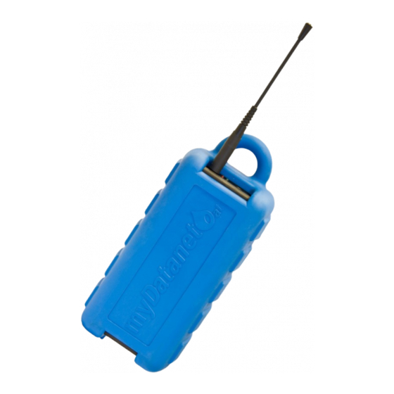
User manual for the portable data logger
Rev. 01 valid from:
myDatalog4
Firmware version: 01v025
l
Modem version: 02v001
l
Server version: 40.8
l
Hardware version: 01v006
l
Microtronics
Engineering GmbH |
Hauptstrasse 7 | 3244 Ruprechtshofen | Austria
Tel +43 2756 77180 23 | Fax +43 2756 77180 33 | support@microtronics.at
www.microtronics.at
Advertisement
Table of Contents

Related Manuals for Microtronics myDatalog4


Summary of Contents for Microtronics myDatalog4
- Page 1 Rev. 01 valid from: Firmware version: 01v025 Modem version: 02v001 Server version: 40.8 Hardware version: 01v006 Microtronics Engineering GmbH | www.microtronics.at Hauptstrasse 7 | 3244 Ruprechtshofen | Austria Tel +43 2756 77180 23 | Fax +43 2756 77180 33 | support@microtronics.at...
-
Page 3: Chapter 1 Table Of Contents
Chapter 1 Table of contents Chapter 1 Table of contents User manual for the portable data logger myDatalog4 Chapter 1 Table of contents Chapter 2 Declaration of conformity Chapter 3 Specifications Chapter 4 General specifications 4.1 Translation 4.2 Copyright 4.3 General descriptive names 4.4 Safety instructions... - Page 4 6.1 Inspection of incoming deliveries 6.2 Scope of supply 6.3 Storage 6.4 Transportation 6.5 Return Chapter 7 Installation 7.1 Dimensions 7.2 Installing the myDatalog4 7.2.1 Wall mounting 7.2.2 Suspended installation 7.3 Electrical installation 7.3.1 Connecting the sensors 7.3.1.1 Connection examples 7.3.1.1.1 Analogue modes 7.3.1.1.2 Digital modes (use of the 14VDC sensor supply)
- Page 5 8.2 General principles 8.3 Placing the system into operation 8.4 Testing communication with the device Chapter 9 User interfaces 9.1 User interface on the myDatalog4 9.1.1 Operating elements 9.1.1.1 Solenoid switch 9.1.1.2 Status LED 9.2 User interface on the myDatanet-Server 9.2.1 Site configuration...
- Page 6 9.2.1.6 Alarm settings 9.2.1.7 Basic setting 9.2.1.8 FTP export settings 9.2.2 Device configuration 9.2.2.1 Comments 9.2.2.2 Measurement instrument 9.2.2.3 Device-specific settings 9.2.2.4 GPRS Chapter 10 XML interface 10.1 General 10.2 Structure of the database 10.2.1 Generally applicable table identifiers 10.2.1.1 mydatalog4id 10.2.1.2 geraetid 10.2.1.3 bookingline (read only) 10.2.1.4 kundeid...
- Page 7 Chapter 1 Table of contents 10.3.1.1.2 List of site types 10.3.1.1.3 Filter conditions 10.3.1.1.3.1 Example: 10.3.1.1.4 Fields 10.3.1.1.4.1 Example 10.3.1.1.5 Data retrieval including index specifications 10.3.1.1.5.1 Example 10.3.1.2 Data record compression 10.3.1.3 Updating data fields 10.3.1.3.1 Example 10.3.2 Format of the XML result 10.3.2.1 Example: 10.3.3 Format of the JSON result 10.3.3.1 Example...
- Page 8 11.6.1 Calibration guidelines 11.6.2 Equipment required for the calibration 11.6.3 Calibration process Chapter 12 Removal/disposal Chapter 13 Troubleshooting and repair 13.1 General problems 13.2 Log entries and error codes 13.2.1 Modem error 13.3 Evaluating the device log 13.3.1 Evaluating the device log on the myDatanet server 13.3.2 Evaluating the device log using DeviceConfig Chapter 14 Spare parts and accessories 14.1 Assembly sets...
-
Page 9: Chapter 2 Declaration Of Conformity
Chapter 2 Declaration of conformity Chapter 2 Declaration of conformity Rev. 01... -
Page 11: Chapter 3 Specifications
Operation Solenoid switch for initiating ALOHA transmission mode 1 x USB slave for establishing a connection to a PC. The DeviceConfig configuration interface program must be installed on the PC to enable communication with the myDatalog4 . Antenna FME-M connector... - Page 12 Data By means of GSM/GPRS quad-band modem to the respective myDatanet server transmission The myDatalog4 is equipped with an integrated SIM card. Country list profile of the SIM chip: 0 (see www.microtronics.at/footprint) Monthly t.b.d at two-minute measurement cycle and 120-minute transmission cycle...
-
Page 13: Chapter 4 General Specifications
4.4 Safety instructions For the connection, commissioning and operation of the myDatalog4 , the following information and higher legal regulations of the country (e.g. ÖVE), such as valid EX regulations as well as the applicable safety and accident prevention regulations for the respective application case must be observed. -
Page 14: General Safety Instructions
Important note: The manufacturer's products that are designed for use outdoors include extensive protection against penetrating moisture and dust. 4.4.1 Use of the hazard warnings DANGER: Indicates a potential or threatening hazardous situation that will result in death or serious injuries if not avoided. - Page 15 Chapter 4 General specifications Important note: No liability shall be assumed at any time and under no condition for the connection via a GSM/GPRS modem for whose use radio signals and networks are utilized, The GSM/GPRS modem must be switched on and be operated in an area where sufficient signal strength is present.
- Page 16 4.5 Overview Bottom of the myDatalog4 Top of the myDatalog4 (view without rechargeable battery or battery pack) 1 Sensor connector 4 Solenoid switch 2 USB interface 5 Status LED 3 Supply connector 6 Antenna connection Rev. 01...
-
Page 17: Block Diagram
Chapter 4 General specifications 4.6 Block diagram Block diagram of the myDatalog4 4.7 Intended use The portable measurement instrument is used to collect analogue and digital signals. The device is battery-operated. The measured and recorded data is stored on a non-volatile memory medium. -
Page 18: General Product Information
To save energy, the voltage output can be configured in such a way that it is only activated just before and during a measurement. The myDatalog4 is also equipped with a battery voltage output (3,6...4,1V ). The voltage at the battery voltage output is always available and can be used to supply the switch contacts (e.g. -
Page 19: Device Labelling
Chapter 4 General specifications 4.9 Device labelling The specifications in this user manual apply exclusively to the myDatalog4 device type. The type plate is located on the rear side of the device and contains the following specifications: Type designation Serial number... -
Page 20: Obligation Of The Operator
28) via the solenoid contact so that the amended configuration is transferred to the myDatalog4 . During this process, all of the data that has not yet been transferred to the myDatanet server is transferred. The sensor cable and antenna can be removed as soon as the GPRS connection has been deactivated - indicated by the status LED going out (see "Status LED"... -
Page 21: Chapter 5 Functional Principle
Functional principle myDatalog4 with integrated managed service SIM card (including data transmission) 2 myDatanet server to which the data is transferred 3 Client that accesses the interface of the myDatanet server via the web browser 4 Customer-specific server that provides clients with their own interface. - Page 22 Functions and components provided by myDatanet : myDatalog4 The myDatalog4 is a portable device for connecting sensors (UI1-4 ) to the myDatanet server (GPRS). Managed Service Managed Service is the basis for operating your devices and provides you with a wide range of services.
-
Page 23: Internal Processing Of The Measurement Values
Chapter 5 Functional principle 5.1 Internal processing of the measurement values Diagram of the internal processing of the measurement values 1 Monitoring of the measurement range limits 4 Recording of the measurement values (see 1)2) (see "Overflow module" on page 23) "Record module"... - Page 24 The following table specifies the relevant parameters for the module: Configuration section Mode Parameter Explanation Measurement channels - Digital >Config. Cnt.Day Cnt.Intervl. 0-20 mA Overflow Procedure in the event of measurement range violations 4-20 mA 5.1.2 Scale module This module rescales the raw value (e.g. mA) to the required measurement value (e.g. mm). The number of edges that have been added up from the counter module is used for the "Cnt.Day"...
-
Page 25: Alarm/Trigger Module
Chapter 5 Functional principle The following table specifies the relevant parameters for the module: Configuration section Mode Parameter Explanation Measurement channels -> Digital Invert Inverts the input signal Basis Cnt.Day Impulse Metered measurand of a pulse in the measurement unit Cnt.Intervl. -
Page 26: Record Module
Configuration section Parameter Explanation Alarm settings On alarm The alarm is recorded in the alarm list. On warning On fault alarm Ü An immediate transmission is initiated. On fault warning 5.1.4 Record module The record module records the measurement values. If necessary, the record interval or transmission cycle is modified depending on the global triggers set by the alarm/trigger module. -
Page 27: Day Change
Chapter 5 Functional principle filter is used to filter out any signal faults, a minimum pulse length of 20msis required for the correct detection of the pulses. The counter module adds the number of rising edges and transfers this number to the scale module as soon as the time of a measurement is reached. The following table specifies the relevant parameters for the module: Configuration section Mode... -
Page 28: Aloha Transmission Mode
5.3 ALOHA transmission mode ALOHA transmission mode is a special connection mode whereby the myDatalog4 establishes a connection to the myDatanet server for 10min. InitiatingALOHA transmission mode: Directly on the device using the solenoid switch (see "Solenoid switch" on page 57). The GSM network is re-selected during this process. -
Page 29: Automatic Selection Of The Gsm Network
Chapter 5 Functional principle 5.4 Automatic selection of the GSM network The GSM network to which the device should register must be selected, as the myDatalog4 is equipped with a SIM chip that provides a mobile connection via a variety of international service providers (see www.microtronics.at/footprint ). - Page 30 search for GSM networks in the receiving range is completed once the ban list is deleted and the network selection is completed with the ban list that is now empty (see step 3 in chapter"Automatic selection of the GSM network" on page 29). Rev.
-
Page 31: Chapter 6 Storage, Delivery And Transport
Note: The rechargeable battery or battery pack required for operation is not part of the stand- ard scope of supply and must be ordered separately (see "Rechargeable battery and battery packs" on page 139). The standard scope of supply of the myDatalog4 (206.204) includes: myDatalog4 Antenna 900 FME -F (206.801) Extension cable for antenna FME-F/FME-M 5m (206.805) - Page 32 15...90%rH Note: The table above contains only the storage conditions for the two energy sources used most frequently for the myDatalog4 . Please consult the appropriate factsheet for information about the storage conditions of other rechargeable battery or battery packs.
-
Page 33: Chapter 7 Installation
7.2 Installing the myDatalog4 Important note: Ensure installation is completed correctly. Comply with existing legal and/or operational directives. Improper handling can cause injuries and/or damage to the instruments! The myDatalog4 must not be operated in the field without a protective armour. Rev. 01... - Page 34 The installation site must be selected according to specific criteria. The following conditions must be avoided in any case: Direct sunlight Objects that radiate intense heat (maximum ambient temperature: -20...+50°C) Objects with a strong electromagnetic field (frequency converter or similar) Corrosive chemicals or gases Mechanical impacts Direct installation on paths or roads...
-
Page 35: Wall Mounting
Chapter 7 Installation 7.2.1 Wall mounting The optional "MDN wall mounting (206.321 )" equipment is required for wall mounting. The myDatalog4 can also be secured against theft using the optional "MDN Anti-theft device " (206.322) equipment. Wall mounting - step 1... - Page 36 3. Carefully bend the brackets on the retaining bracket (1) apart and insert the myDatalog4 in accordance with the Figure "Wall mounting - step 2" on page 35. The rear of the myDatalog4 (the side with the cut-out in the protective armour) must be facing the wall.
-
Page 37: Suspended Installation
1 Niro shackle (206.325) 2 myDatalog4 1. Use the Niro shackle (206.325), to attach the myDatalog4 to a rung of the channel ladder or a similar fastening point in accordance with the figure "Detailed view of a suspended installation " on page 37. -
Page 38: Electrical Installation
7.3 Electrical installation Important note: Only qualified personnel should undertake the installation described in this chapter of the operating instructions to avoid any damage to the device. 7.3.1 Connecting the sensors Important note: Ensure installation is completed correctly. Comply with existing legal and/or operational directives. Improper handling can cause injuries and/or damage to the instruments! Run all data cables so that they do not pose a trip hazard and ensure that cables do not have any sharp bends. - Page 39 Chapter 7 Installation Sensor connector Sensor connector (7- Connection cable 7-pins for Signal pin MIL connector) sensors 2,8m (206.602) Universal input 3 Universal input 4 Switchable 14VDC sensor supply Sensor connector Universal input 2 Universal input 1 Battery voltage output (3,6...4,1V ) Ground Connection cable 7-pins for sensors 2,8m...
- Page 40 LED should then start to flicker (see "Status LED" on page 58), indicating that a connection is being established. Note: If the myDatalog4 is still in transport mode, the transport lock is deactivated by the initiation of ALOHA transmission mode and the device starts to operate in accordance with the configuration.
- Page 41 Chapter 7 Installation 7.3.1.1 Connection examples 7.3.1.1.1 Analogue modes Connection example: Analogue modes 1 myDatalog4 3 3-wire mA sensor 2 2-wire mA sensor Rev. 01...
- Page 42 7.3.1.1.2 Digital modes (use of the 14VDC sensor supply) Connection example: Digital modes (use of the 14VDC sensor supply) 1 myDatalog4 3 Sensor with open collector output 2 Isolated relay contact Note: If universal input 1 is to be operated in "Cnt.Day" or "Cnt.Intervl." channel mode, the sensor supply must be switched on permanently.
- Page 43 Chapter 7 Installation 7.3.1.1.3 Digital modes (use of 3,6...4,1V battery voltage output) Connection example: Digital modes (use of 3,6...4,1V battery voltage output) 1 myDatalog4 3 Sensor with open collector output 2 Isolated relay contact Note: This connection method is especially suited for the universal input 1, if it is operated in "Cnt.Day" or "Cnt.Intervl."...
- Page 44 The Splitter cable for myDatalog Mobile (206.679) only splits the sensor connector in to two identical 7-pin MIL connectors, which means that the pin assignment of the two connectors corresponds to that of the sensor connector of the myDatalog4 (see "Connecting the sensors" on page 38).
-
Page 45: Connecting The Gsm Antenna
The standard antenna is directly attached to the antenna connector (see "Overview" on page 16) of the myDatalog4 . In the event of a low radio signal strength, you can use the Flat antenna Smart Disc FME-F 2,5m (206.814). - Page 46 1. If you need an antenna extension, connect it to the antenna first. 2. Connect the antenna extension or antenna directly to the antenna connector of the myDatalog4 (see "Overview" on page 16). Important note: Do not apply too much force when tightening the antenna. Tighten the antenna or antenna extension with your hand.
- Page 47 7.3.2.1.3 Procedure for determining the optimum position of the antenna 1. Install the myDatalog4 as described in chapter "Installing the myDatalog4 " on page 33. During this process, also observe the notes regarding the influences on the signal quality (see "Typical influences on the signal quality"...
-
Page 48: Technical Details About The Universal Inputs
7.3.3 Technical details about the universal inputs Note: The universal inputs are not galvanically isolated. The myDatalog4 is equipped with a 12 bit ADC. Schematic diagram of an universal input If the universal input is operated in one of the analogue modes ("0-20 mA" or "4-20 mA"), switch S1 is closed and the 1k resistance is thus bypassed. - Page 49 Chapter 7 Installation 7.3.3.1 0/4...20mA mode Resolution 6µA 25mA Load 100Ω 7.3.3.2 Digital modes (digital, day counter, pulse counter) When using digital modes, the switching thresholds can be configured via the "High level" parameter. The parameter is located in the "Config" tab of the "Measurement channels" configuration section (see "Measurement channels"...
- Page 50 The sensor supply is activated by setting the warmup time in the "Basic settings" configuration section (see "Basic setting" on page 70). The warmup time specifies how long the sensor supply is switched on before the measurement. If the setting is 0 seconds, the sensor supply is not activated before or during the measurement.
- Page 51 Chapter 7 Installation Note: Example to explain the relationship between the warmup time and the record interval (warmup time > record interval): Basic setting Record interval 1min. Warmup time 90 seconds Output on the device Sensor supply Explanation: The sensor supply is activated when the time for the first recording following the PowerOn is reached. As the warmup time is longer than the record interval, a measurement and recording cannot be completed at this time.
-
Page 53: Chapter 8 Initial Start-Up
8.3 Placing the system into operation Note: It is recommended that the myDatalog4 is first placed into operation in the office before moving the device to the place of use. During this process, you should set a site for the later operation on the myDatanet server (see "myDatanet Server Manual "... -
Page 54: Testing Communication With The Device
2. The myDatalog4 is already ready for operation if you have completed all of the steps in chapter "Connecting the sensors" on page 38. 3. Create a site for the operation on the myDatanet server (see "myDatanet Server Manual " 805002). - Page 55 Chapter 8 Initial Start-Up 6. Check the incoming data in the ALOHA data window of the myDatanet server, which can be accessed by clicking on the speech bubble with the "Aloha" inscription (see "myDatanet Server Manual " 805002). Particular attention must be paid to the internal"GSM level" and "Battery"...
-
Page 57: Chapter 9 User Interfaces
Chapter 9 User interfaces Chapter 9 User interfaces The configuration of the myDatalog4 is carried out via the web interface on the myDatanet server (see "User interface on the myDatanet-Server" on page 59), which your responsible sales partner will provide to you. - Page 58 If the ALOHA transmission mode was activated or the rechargeable battery or battery pack was connected (PowerOn), the myDatalog4 switches to advanced signalling mode and indicates the current operating state for 10 minutes via the status LED. During these 10 minutes, the error/status codes are issued every 3 seconds as long as there is no active GPRS connection.
-
Page 59: Site Configuration
Chapter 9 User interfaces Operating states Status LED Description Flickering Establishing connection Lights up GPRS connection established or button/solenoid switch actuated Normal measuring operation according to configuration until the next transmission 9.2 User interface on the myDatanet-Server 9.2.1 Site configuration Note: Several of the configuration fields in the following sub chapters may possibly be hidden depending on the respective user level. - Page 60 Mode Basic settings for the measurement channel Universal Measurement channel deactivated inputs Digital Invert Inverts the input signal (digital Cnt.Day Impulse Metered measurand of a pulse in the measurement unit modes) Defines the upper scale end of the pointer instruments Unit String that is used as a measurement unit by all of the server display elements [0-16 characters]...
- Page 61 Chapter 9 User interfaces 9.2.1.3.2 Config Universal inputs Digital High level Configuration of the "low" and "high" level (digital modes) The levels are set automatically. Warmup time not equal to 0: "high": >7V "low": <6,3V Warmup time equal to 0: "high": >1,8V "low": <1,62V >...
- Page 62 Note: Additional explanation regarding the difference between "Cnt.Day" and "Cnt.Intervl." Basic setting Record interval 1min. Measurement value blue line "Cnt.Intervl." mode: The pulses are added up and reset "Cnt.Day" mode: All of the pulses up to the day after each recording. changing time are added up.
- Page 63 Chapter 9 User interfaces Universal inputs 4-20 mA Overflow Procedure in the event of measurement range violations (4-20mA mode) Ignore The measurement value is calculated beyond the range limits. Silent The measurement value is truncated at the cutoff range limits. Out of The error value "OL"...
- Page 64 9.2.1.3.3 Alarms "Digital" mode A "high" at the universal input triggers a "warning". A "high" at the universal input triggers an "alarm". A "high" at the universal input triggers a "fault warning". A "high" at the universal input triggers a "fault alarm". All other modes Warning Value low A warning is triggered, if the measurement value...
- Page 65 Chapter 9 User interfaces Mode Possible calculation modes for the calculated channels Calculated channel deactivated Table Defines the lower scale end of the pointer instruments Defines the upper scale end of the pointer instruments Unit String that is used as a measurement unit by all of the server display elements [0-16 characters] Decimal Number of decimal places that are used by all of the server display...
- Page 66 9.2.1.4.2 Calculation Calculated channel deactivated Table Source Selection of the channel from which the input data is used Opens the screen for entering the values table (the table rows are interpolated linearly, values outside of the defined table are extrapolated linearly.) Digital Source...
- Page 67 Chapter 9 User interfaces Source Calculated channel 1 Calculated channel 2 Date/time Infinite counter [m Flow rate [m Flow rate [l/h] 26.03.2013 12:50 26.03.2013 12:51 3,600,000 26.03.2013 12:52 1,800,000 26.03.2013 12:53 1005 0.25 900,000 26.03.2013 12:54 1065 3,600,000 Calculation not possible as there is no measurement value before 12:50. Explanation: No values can be determined for the measurement at 12:50 for the calculated channel as there is no previous value and the different between the meter readings cannot be determined.
- Page 68 9.2.1.5.2 Alarms Note: The alarm limits for the internal channels are monitored by the myDatanet server and not the myDatalog4 . This means that an alarm can only be detected when the measurement data is transferred to the myDatalog4 server.
- Page 69 Chapter 9 User interfaces 9.2.1.6 Alarm settings Acknowledgement Standard The global server setting is used to determine whether alarms must be acknowledged automatically or manually.(see "myDatanet Server Manual " 805002) Automatic Alarms are acknowledged automatically as soon as all of the messages have been sent.
- Page 70 9.2.1.7 Basic setting Transmission cycle Time between transmissions Transmission cycle Time between the transmissions, if a shortened transmission cycle should quick be used because of an alarm/warning or a trigger being initiated Record interval Time between measurement data recordings Measure quick divisor record interval = record interval / factor (from triggering) Warmup time specifies the time for which the sensor supply is switched on before the...
-
Page 71: Device Configuration
Chapter 9 User interfaces 9.2.2 Device configuration Note: Several of the configuration fields in the following sub chapters may possibly be hidden depending on the respective user level. In this case, please contact the myDatanet-Server administrator. You can reach the input screen for configuring the device by clicking on the serial number in the site list (see "myDatanet Server Manual "... - Page 72 Firmware Firmware update is deactivated. update As soon as a new version of the selected firmware type is available, this is installed immediately. Even if tag is missing Firmware is also transferred to the device if the device has not transmitted the current firmware version to the server (NOT RECOMMENDED!).
-
Page 73: Chapter 10 Xml Interface
Chapter 10 XML interface Chapter 10 XML interface Important note: The relevant licences are required on the myDatanet server to use the XML interface. If the licence is not available for the XML export, the following message is displayed for every request: " ". - Page 74 Generally applicable table identifiers Identifier Description mydatalog4id Site configuration (see "mydatalog4id" on page 75) geraetid Devices (see "geraetid" on page 81) bookingline Connection list (see "bookingline (read only)" on page 82) kundeid Customers (see "kundeid" on page 83) Device-specific table identifiers Identifier Allocation Description...
- Page 75 Chapter 10 XML interface 10.2.1 Generally applicable table identifiers 10.2.1.1 mydatalog4id This table includes all of the site-specific configurations.. name Site designation (not relevant for the device or data assignment)[2-50 characters] timezone Regional settings (not relevant for raw measurement data as this is stored in the UTC) Value Explanation 99.00...
- Page 76 transfer_alerts Alarm in case the device does not respond for longer than the set number of transmission cycles Value Explanation No alarm settings standard (>2x transmission cycles) immediately (>1x transmission cycle) medium (>5x transmission cycles) long (>10x transmission cycles) extra long (>20x transmission cycles) max_transfer_volume Settings for the transfer volume alarm Value...
- Page 77 Chapter 10 XML interface view Selection of the report that is loaded by clicking on the device link in the maps Value Explanation *OFF* The default graphic is loaded. "viewid" The selected report is loaded.To obtain the "viewid", open the required report (see "myDatanet Server Manual "...
- Page 78 min4 - min7 Channel mode Explanation Measurement channel deactivated Digital Cnt.Day Cnt.Intervl. 4-20 mA Start of the measurement range in the measurement unit 0-20 mA max4 - max7 Channel mode Explanation Measurement channel deactivated Digital Cnt.Day Defines the upper scale end of the pointer instruments Cnt.Intervl.
- Page 79 Chapter 10 XML interface decpl4 - decpl7 Number of decimal places that are used by all of the server display elements Important note: The content of the field must be set to 0 for Digital channel mode (no decimal places) Value Explanation Standard...
- Page 80 units8 Int. temp: Selection of the temperature unit used by all of the server display elements alarm_low8 An alarm is triggered, if the measurement value drops to or below this value. alarm_high8 An alarm is triggered, if the measurement value meets or exceeds this value. hysterese8 Hysteresis for the all-clear in the event of an alarm/warning (e.g.
- Page 81 Chapter 10 XML interface 10.2.1.2 geraetid This table includes general information and configurations that are the same for all devices of the myDatanet range. kunde Unique data record number of the customer to whom the device is assigned (read only) conn_path Specifies the communication channel via which the last connection was established Value...
- Page 82 fw_update Settings for the firmware update Value Explanation Off: Firmware update is deactivated. On: As soon as a new version of the selected firmware type is available, this is installed immediately. Even if tag is missing: Firmware is also transferred to the device if the device has not transmitted the current firmware version to the server (NOT RECOMMENDED!).
- Page 83 Chapter 10 XML interface cmh_quantity Amount of received data in bytes (device to the server) cmh_code Indicates whether the device has established a connection to the myDatanet server (41=closed, 942=connected) Important note: Table entries with different codes to the ones mentioned above include information that is only intended for internal use and that should be filtered out by the customer.
- Page 84 10.2.2 Device-specific table identifier 10.2.2.1 mydatalog4data This table contains the measurement data of the myDatalog4 (see "Internal channels" on page 68, "Measurement channels" on page 59 and "Calculated channels" on page 64). Rev. 01...
- Page 85 10.2.2.3 mydatalog4_usrcfg This table contains the device-specific configurations (configuration of the universal inputs, basic settings and alarm settings) that are transferred to the myDatalog4 . These device-specific configurations are supplemented with the configuration from the "geraetid" table (see "geraetid" on page 81) that is the same for all of the myDatanet devices.
- Page 86 mode1 - mode4 Basic settings for the measurement channel Value Explanation Measurement channel deactivated Digital 4-20 mA 0-20 mA Cnt.Day Cnt.Intervl. Important note: If the measurement channel mode is set to Digital, the following additional settings are required: In the "mydatalog4id" table, the content of the "units" field (measurement unit) must be deleted for the relevant measurement channel.
- Page 87 Chapter 10 XML interface high_level1 - high_level4 Configuration of the "low" and "high" level (only for channels in "Digital", "Cnt.Day" or "Cnt.Intervl." mode) Value Explanation The levels are set automatically. Warmup time not equal to 0: "high": >7V "low": <6,3V Warmup time equal to 0: "high": >1,8V "low": <1,62V...
- Page 88 alarm_record_faulthi The "Fault alarm" is recorded in the alarm list (read only). alarm_tx_alarmlo An immediate transmission is initiated in the event of a "Warning". alarm_tx_alarmhi An immediate transmission is initiated in the event of an "Alarm" (read only). alarm_tx_faultlo An immediate transmission is initiated in the event of a "Fault warning". alarm_tx_faulthi An immediate transmission is initiated in the event of a "Fault alarm".
- Page 89 The following applies for these fields: Value Explanation 10.2.2.4 mydatalog4_cmds This table contains the configuration of the operating mode that is transferred to the myDatalog4 . measure_mode Value Explanation Measurement deactivated Measurement active...
- Page 90 sensor_sn Serial number of the sensor circuit board accu_sn Serial number of the rechargeable battery or battery pack instrument_state Error/status code of the device (see "Status LED" on page 58) sim_id IMSI of the SIM chip sim_apn APN that was used for the last connection net_mcc MCC (mobile country code) of the network that was used for the last connection net_mnc...
- Page 91 Level, which has not been reached or exceeded, that has caused the alarm/warning to be triggered or reset 10.2.2.7 mydatalog4_compcfg This table contains the trigger and alarm configuration for the universal inputs that are transferred to the myDatalog4 . Context Unique data record number of the site (read only) Rev. 01...
- Page 92 alarm_low_lower1 - alarm_low_lower4 A warning is triggered, if the measurement value drops to or below this value. alarm_low_upper1 - alarm_low_upper4 A warning is triggered, if the measurement value meets or exceeds this value. alarm_high_lower1 alarm_high_lower4 An alarm is triggered, if the measurement value drops to or below this value. alarm_high_upper1 - alarm_high_upper4 An alarm is triggered, if the measurement value meets or exceeds this value.
- Page 93 Chapter 10 XML interface The following applies for these fields: Value Explanation 10.2.2.8 mydatalog4aloha This table contains the ALOHA data that is generated every three seconds independently of the normal measurement values and is thus not saved with the standard measurement data (see "ALOHA transmission mode"...
- Page 94 Information about the five GSM cells in the receiving range that were used to determine the position gsm_mcc_0 - gsm_mcc_4 MCC (mobile country code) of the GSM cell gsm_rssi_0 - gsm_rssi_4 Received GSM level [dBm] for the GSM cell gsm_mnc_0 - gsm_mnc_4 MNC (mobile network code) of the GSM cell gsm_ta_0 - gsm_ta_4 TA (timing advance) of the GSM cell...
- Page 95 Chapter 10 XML interface Parameter Explanation {update} OPTIONAL Update of data fields in the query result (e.g. ) (see "Updating &$field01=33 data fields" on page 102) {data_type} OPTIONAL Selection of the output format: XML document (see "Format of the XML result" on page 103) JSON document (see "Format of the JSON result"...
- Page 96 You can access a list of all the types of sites that are supported by the myDatanet server by specifying the xPath query SiteTypes https://server-URL:8080/SiteTypes?user=u1&password=p1 Result: <Result> <SiteType class="2700" title="myDatalog4"> FFFF2700 </SiteType> </Result> 10.3.1.1.3 Filter conditions The filter condition is always within square brackets and comprises expressions that can be linked by keywords such as .
- Page 97 Time stamp within single inverted commas ' Formats (comma, date format, etc.) are adopted from the user or server settings. 10.3.1.1.3.1 Example: The configuration of all sites of the type myDatalog4 is displayed if no filter conditions are provided. https://server-URL:8080/mydatalog4id?user=u1&password=p1 Result: <Result>...
- Page 98 (e.g. FFFF0005 for the table identifier). geraetid 10.3.1.1.4.1 Example The following example provides the names of all sites of the type myDatalog4 https://server-URL:8080/mydatalog4id/(name)?user=u1&password=p1 Result: <Result> <mydatalog4id id="A1526911CF9CCAA0" stamp="8.2.2013 11:48:16">...
- Page 99 Chapter 10 XML interface 10.3.1.1.5.1 Example The following example provides the first data record of a myDatalog4 type site that is called "Site1". https://server-URL:8080/mydatalog4id[name='Site1']/mydatalog4data[0] ?user=u1&password=p1 Result: <Result> <measurement_values id="F10001C000000000" stamp="9.4.2013 09:30:00"> <tag>00002700</tag> <context title="Site">A19D60AC2883F9B3</context> <ch1 title="Channel 1" units="%">10</ch1> <ch2 title="Channel 2" units="%">20</ch2> <ch3 title="Channel 3" units="%">11</ch3> <ch4 title="Channel 4" units="%">80</ch4> <calc60 title="Calculation channel 1" units="%" calc="1"/> <calc61 title="Calculation channel 2" units="%" calc="1"/> <calc62 title="Calculation channel 3" units="%" calc="1"/>...
- Page 100 Specifies that the serial number for the device, for which the date has to be queried, is "010146AF251D0BA9". mydatalog4id Specifies that the data of a myDatalog4 type site should be queried. mydatalog4data Specifies that the data from the "Measurement data" table should be queried.
- Page 101 Chapter 10 XML interface The example above provides three different results for the values of channel 0 compressed over 15 min.: ch0(method=1): Minimum within the compression period ch0(method=2): Maximum within the compression period ch0(method=16;sum_mode=4): Daily total over the compression period Assumption: The value of channel 0 increases by one per minute. <Result>...
- Page 102 Note: The user must have the relevant rights to modify the data (see tbd). 10.3.1.3.1 Example The following example sets the "Firmware update" to "ON" and the "Firmware type" to "Release candidate" for all of the devices that are compatible with the myDatalog4 type site. https://server-URL:8080/geraetid[devclass=2700]?user=u1&password=p1 &$fw_update=1&$fw_release_type=1...
- Page 103 Specifies that the entry point for the request is the device table. [devclass=2700] Specifies that the action should apply to all of the devices that are compatible with the myDatalog4 type site. $fw_update=1 Specifies that the "Firmware update" should be set to "On".
- Page 104 The data fields have the following attributes: Attribute Explanation title Title of the data field (for measurement data this is dependent on the site settings) units Units of the data field for measurement data (dependent on the site settings) calc OPTIONAL Is only displayed if it is a channel that has been calculated by the sever 10.3.2.1 Example:...
- Page 105 Chapter 10 XML interface The objects that represent the fields of the table have the following properties: Properties Explanation name Internal field designation title Title of the data field (for measurement data this is dependent on the site settings) units Units of the data field (for measurement data this is dependent on the site settings) value Value of the data field...
- Page 106 10.4 XML import The XML import is designed to import the data generated or changed via the user interface, created by the customer, back into the myDatanet server. Only existing measurement data and settings can be changed or new measurement data can be added.
- Page 107 Chapter 10 XML interface Parameter Explanation {IP-Address} Address of the server to which the data should be transferred (myDatanet server) {Port} Port on which the HTTP server is running. Standard value is 80. {login} The direct login parameter clearly identifies the user on the server. Each relevant user can only request his own parameter.
- Page 108 <?xml version="1.0"?> <Result> <mydatalog4data id="F000002200000282" > <ch1>0,0000</ch1> </mydatalog4data> </Result> mydatalog4data Not relevant for the data import. However, it is recommended to use the relevant table identifier. Unique identification number of the data record that is going to be modified Value to which the measurement value of channel 1 should be changed 10.4.3.2 Importing data attribute must be specified if a new data record is going be created.
- Page 109 Chapter 10 XML interface mydatalog4data Not relevant for the data import. However, it is recommended to use the relevant table identifier. must always be specified when importing data. A new data record with an id="0" automatically generated ID is created. stamp OPTIONAL Time stamp that should be used for the data record.
-
Page 111: Chapter 11 Maintenance
Inspect the myDatalog4 regularly for mechanical damage. Check all cables for mechanical damage at regular intervals. Clean the myDatalog4 with a soft, moist cloth. Use a mild cleaning agent, if necessary. 11.2 Accu or battery pack While battery packs are intended for single use and must be disposed of accordingly after depletion, accu packs can be recharged and used again and again. - Page 112 4. Briefly (approx. 1 sec.) activate the solenoid switch (see "Operating elements" on page 57) to prepare the myDatalog4 for the removal of the rechargeable battery pack. This ensures that the most recently generated data is saved permanently. If the device is not notified that the rechargeable battery pack is being removed by briefly pressing the solenoid switch, the meas- urement data from the last half an hour can be lost.
- Page 113 7. Due to the low energy consumption, one rechargeable battery charge will provide several months of operating time. During this time, the myDatalog4 is located in an environment that strongly corrodes the seal between the device and the rechargeable battery or battery pack.
- Page 114 Fitting the protective armour Step 1 Step 2 Step 3 11.3.1 Charging the accu pack The accu packs are delivered in a charged state. Instructions on replacing the accu pack are provided in "Replacing the rechargeable battery or bat- tery pack" on page 111. Important note: Additional safety instructionsThe manufacturer's products that are designed for use outdoors include extensive protection against penetrating moisture and dust.
- Page 115 Chapter 11 Maintenance Charger and accu pack 1 Charger AC15 (206.701) 3 Charging plug 2 Status LED of the Charger AC15 4 Accu pack, e.g. AP424DA rechargeable battery (206.705) Flashing orange: Impulse charge (accu pack fully discharged) Orange: Accu pack is being charged Green: Charging completed Red: Accu pack damaged The charging process starts as soon as the accu pack is connected to the charger.
- Page 116 Important note: The use of spare and wear parts (e.g. accu or battery packs, etc.) that are not approved by the manufacturer will render the warranty invalid. Note: Ensure that accu and battery packs are disposed of in line with environmental require- ments.
- Page 117 The seal must be protected before EACH assembly with a bead of grease from the syringe included in the myDatanet service kit (206.324 ). 1. After removing the accu or battery pack, clean the contact surface on the myDatalog4 with a standard cleaning cloth and cotton buds.
- Page 118 Cleaning the myDatalog4 - step 1 Cleaning the myDatalog4 - step 2 2. Clean the seal and area around the seal of the accu or battery pack with a cleaning cloth and cotton buds. Cleaning the accu or battery pack 3. To ensure impermeability, it is particularly important to apply a bead of grease on the seal (approx.
- Page 119 Chapter 11 Maintenance 11.4 Maintenance of the antenna socket The optional "myDatanet service kit (206.324 )" equipment is required for maintaining the antenna socket. Important note: The three small O-rings must be installed on the contact pin of the antenna socket to improve the seal.
- Page 120 Antenna including assembled O-ring 1 Antenna 900 FME -F (206.801) 2 6.1x1.6 mm O-ring (included in the scope of delivery of the 206.324 ) 1. Assemble the O-ring on the antenna connector according to the Figure "Antenna including assembled O-ring" on page 120. 2.
- Page 121 (see "Overview" on page 16). 3. Connect the myDatalog4 to the PC using the cable USB cable USB-A/USB-B 1,5m (206.601) sup- plied. The driver will need to be installed, if the device is being connected to the PC for the first time.
- Page 122 122) and wait for the warmup time to elapse. 6. Connect the myDatalog4 to your constant current source. You can use the Connection cable 7- pins for sensors 2,8m (206.602) or Cable connector 7-pins for myDatalogMobile (206.654) available as accessories for this purpose.
- Page 123 Chapter 11 Maintenance 7. Set your current source to the value that you want to use for the lower reference point and wait 3-5 seconds until the value displayed by the DeviceConfig has stabilised. Ensure that the required value is entered for the lower reference point before you press the button to adopt the lower reference point for the relevant universal input.
- Page 124 "Calibration" tab 1 Lower reference point (target value in mA) 6 Calculated slope 2 Upper reference point (target value in mA) 7 Button for adopting the lower reference point for universal input 1 3 Raw value 8 Button for adopting the upper reference point for universal input 1 4 Rescaled raw value in mA (calculated with 9 Button for adopting the lower reference...
- Page 125 The current sources must all be set to the same value during this process. 9. Press the "Save" button to transfer the calculated offset and slope values to the myDatalog4 (see ""Calibration" tab " on page 124).
-
Page 127: Chapter 12 Removal/Disposal
Dispose of the device in accordance with the locally valid environmental regulations for electronic products. Accu and/or battery packs must not remain connected to the myDatalog4 after discharging. Ensure that accu and battery packs are disposed of in line with environmental requirements. -
Page 129: Chapter 13 Troubleshooting And Repair
Communication Evaluate the status LED blink code (see "Status LED" on page 58). Load the device log from the myDatalog4 or the myDatanet server and problems use DeviceConfig for the evaluation (see "Evaluating the device log" on page 137). -
Page 130: Log Entries And Error Codes
13.2 Log entries and error codes Log entry Parameter Description Code Plain text Code Plain text 1011 BSL RESET Rest of the device so that the boot loader can activate the new main controller software 1020 ERROR SOD Internal system error There may be a hardware problem if this error is contained in the device log several times with the same parameter code. - Page 131 Chapter 13 Troubleshooting and repair Log entry Parameter Description Code Plain text Code Plain text 1160 FILE INTEGRITY DATA_FILE While searching for the required data record in the data memory area, it was determined that the data is not sorted in ascending order.
- Page 132 Log entry Parameter Description Code Plain text Code Plain text 1250 MODEM TO ON Timeout when trying to initialise the GPRS modem Timeout during the second attempt to initialise the GPRS modem 1251 MODEM TO INIT Timeout when changing the GPRS modem from the "Not initialised"...
- Page 133 Check the connection between the device and sensor. HOLD Standby (GPRS ON, measurement OFF) If the ALOHA transmission mode is initiated, the myDatalog4 switches back into "RUN" mode (GPRS ON, measurement ON). TRANSPORT Transport lock (GPRS OFF, measurement OFF) see "Standby"...
- Page 134 Try again later BEARER NO -992 --- No answer ANSWER Try again later Check whether the device is in the coverage area (www.microtronics.at/footprint). BEARER NO -991 --- No carrier CARRIER Try again later Check whether the device is in the coverage area (www.microtronics.at/footprint).
- Page 135 BEARER GPRS STOP -975 --- Internal error UNKNOWN 1200 NETLOCK FAILURE -970 --- Error when selecting the network Check whether the device is in the coverage area (www.microtronics.at/footprint). Check the settings for the netlock or remove the netlock Rev. 01...
- Page 136 Try to improve the position of the antenna. Check whether the device is in the coverage area (www.microtronics.at/footprint). TCP channel error (1/2) 1200 CHANNEL ABORTED -965 --- An attempt is being made to write to/read a TCP client that is no longer available.
- Page 137 13.3.2 Evaluating the device log using DeviceConfig The DeviceConfig program can be used to read all of the stored log entries, including those that have not yet been transferred to the myDatanet server, directly from the myDatalog4 via the USB interface.
- Page 138 A more detailed description about the evaluation of the device log using DeviceConfig is included in the user manual for the DeviceConfig ("myDatanetDeviceConfig Manual " 805004). Rev. 01...
-
Page 139: Chapter 14 Spare Parts And Accessories
Chapter 14 Spare parts and accessories Chapter 14 Spare parts and accessories 14.1 Assembly sets Description Quantity Order number MDN wall mounting 206.321 Niro shackle 206.325 14.2 Antennas Description Quantity Order number Antenna 900 FME -F 206.801 Extension cable for antenna FME-F/FME-M 5m 206.805 Antenna 1800 FME-F 206.809... -
Page 140: Charging Device
14.4 Charging device Description Quantity Order number Charger AC15 206.701 Snap-on primary plug EU for chargers/power supplies 300027 Snap-on primary plug UK for chargers/power suppliest 300028 Snap-on primary plug US for chargers/power supplies 300029 Snap-on primary plug AUS for chargers/power supplies 300030 14.5 Cable Description... -
Page 141: Chapter 15 Document History
Chapter 15 Document history Chapter 15 Document history Rev. Date Changes 08.07.2014 First version Rev. 01... -
Page 143: Chapter 16 Glossary
The manufacturer's devices are equipped with subscriber identity modules (SIM) ex-works for the purpose of mobile data transmission. The footprint describes the countries and regions, in which a mobile connection is available (see www.microtronics.at/footprint). NaN value The myDatanet uses special encoding to display different error statuses in the measurement values, for example. -
Page 145: Chapter 17 Contact Information
Chapter 17 Contact information Chapter 17 Contact information Support & Service: Microtronics Engineering GmbH Hauptstrasse 7 3244 Ruprechtshofen Austria, Europe Tel. +43 (0)2756 7718023 support@microtronics.at www.microtronics.at Microtronics Engineering GmbH Microtronics Engineering GmbH (Headquarter) Windthorststrasse 5 Hauptstrasse 7 63179 Obertshausen 3244 Ruprechtshofen...
Need help?
Do you have a question about the myDatalog4 and is the answer not in the manual?
Questions and answers