Table of Contents
Advertisement
Quick Links
Advertisement
Table of Contents

Related Manuals for Pfeiffer Vacuum OKTA 18000


Summary of Contents for Pfeiffer Vacuum OKTA 18000
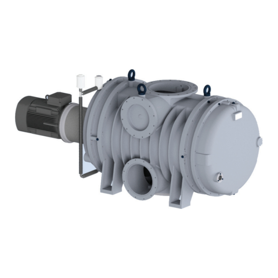
- Page 1 OPERATING INSTRUCTIONS Translation of the Original OKTA 18000 Roots pump...
- Page 2 Dear Customer, Thank you for choosing a Pfeiffer Vacuum product. Your new roots pump should support you in your individual application with full performance and without malfunctions. The name Pfeiffer Vacuum stands for high-quality vacuum technology, a comprehensive and complete range of top-quality products and first-class service.
-
Page 3: Table Of Contents
Product usage limits Proper use Foreseeable improper use Personnel qualification 2.7.1 Ensuring personnel qualification 2.7.2 Personnel qualification for maintenance and repair 2.7.3 Advanced training with Pfeiffer Vacuum Product description Function Identifying product Product features Scope of delivery Transportation and Storage... - Page 4 Recycling and disposal General disposal information Dispose of Okta roots pumps Malfunctions Service solutions by Pfeiffer Vacuum Spare parts 12.1 Set of seals for version with RSSR 12.2 Set of seals for version with axial face seal 12.3 Axial face seal, complete 12.4 Maintenance kit for version with RSSR...
- Page 5 Tbl. 12: Troubleshooting Tbl. 13: Accessories Tbl. 14: Consumables Tbl. 15: Conversion table: Pressure units Tbl. 16: Conversion table: Units for gas throughput Tbl. 17: Materials that make contact with the process media Tbl. 18: Technical data Okta 18000 Standard 5/56...
- Page 6 Connection example with PTC thermistor tripping unit Fig. 12: Position of the vibration sensors Fig. 13: Draining lubricant Fig. 14: Replacing sealing oil for radial shaft seal rings Fig. 15: Overflow valve Fig. 16: Elastic bolt coupling Fig. 17: Dimensions Okta 18000 with overflow valve 6/56...
-
Page 7: About This Manual
Keep the manual for future consultation. 1.1 Validity This operating instructions is a customer document of Pfeiffer Vacuum. The operating instructions de- scribe the functions of the named product and provide the most important information for the safe use of the device. The description is written in accordance with the valid directives. The information in this op- erating instructions refers to the product's current development status. -
Page 8: Pictographs
This section describes all the stickers on the product along with their meanings. Rating plate (example) The rating plate is located on the front side above the sight D-35641 Asslar glass Mod.: Okta 18000 Motor rating plate (not shown) Mod.-No.: PP W90 ... Ser. -No.: 143....max. 2250 1/min Oil: P3 68 l S(N): max. -
Page 9: Abbreviations
About this manual Fig. 1: Position of the stickers on the product 1 Rating plate Note on filling up lubricant 2 Hot surface warning sign Notice D2 3 Direction of rotation arrow (cast in the cover) 1.3.4 Abbreviations Abbreviation Explanation Operating instructions German Institute for Standardization (Deutsches Institut für Normung) Clearance between both coupling halves Rotation speed value of a vacuum pump (frequency, in rpm or Hz) -
Page 10: Safety
Safety 2 Safety 2.1 General safety information The following 4 risk levels and 1 information level are taken into account in this document. DANGER Immediately pending danger Indicates an immediately pending danger that will result in death or serious injury if not observed. ►... - Page 11 Safety Risks during installation DANGER Danger to life from electric shock Touching exposed and voltage-bearing elements causes an electric shock. Improper connection of the mains supply leads to the risk of touchable live housing parts. There is a risk to life. ►...
- Page 12 Safety WARNING Risk of crushing on rotating parts when reaching into the open flange The pistons continue to run in the vacuum after switching off the motor, and can trap fingers and hands within their reach. ► Wait until the vacuum pump comes to a complete standstill. ►...
-
Page 13: Safety Precautions
Safety CAUTION Scalding from hot lubricant Danger of scalding when draining lubricant if it comes into contact with the skin. ► Wear protective equipment. ► Use a suitable collection receptacle. 2.3 Safety precautions Duty to provide information on potential dangers The product holder or user is obliged to make all operating personnel aware of dangers posed by this product. -
Page 14: Proper Use
► Adhere to the installation, commissioning, operating, and maintenance instructions. ► Use only accessory parts recommended by Pfeiffer Vacuum. 2.6 Foreseeable improper use Improper use of the product invalidates all warranty and liability claims. Any use that is counter to the purpose of the product, whether intentional or unintentional, is regarded as improper use;... -
Page 15: Ensuring Personnel Qualification
─ Customer with Pfeiffer Vacuum service training ─ Pfeiffer Vacuum service technician 2.7.3 Advanced training with Pfeiffer Vacuum For optimal and trouble-free use of this product, Pfeiffer Vacuum offers a comprehensive range of courses and technical trainings. For more information, please contact Pfeiffer Vacuum technical training. -
Page 16: Product Description
6 Sight glass 3.2 Identifying product To ensure for a clear identification of the product when communicating with Pfeiffer Vacuum, always keep all of the information on the rating plate to hand. The following information is shown on the rating plates: ●... -
Page 17: Product Features
Product description 3.3 Product features Pump type Pump designs Okta 18000 Standard version: With overflow valve ● Standard motor ● Vacuum flange: DIN 400 PN 10 ● Fore-vacuum flange: ─ Vertical: DIN 400 PN 10 ─ Horizontal: DIN ISO 320 ISO-F ●... -
Page 18: Transportation And Storage
● Fill the gear and bearing chambers with lubricant only once the final installation posi- tion is reached. Preparations for transport Pfeiffer Vacuum recommends keeping the transport packaging and original protective cov- Safe transport of the product 1. Observe weight specified on the rating plate. -
Page 19: Storing Vacuum Pump
Neither the suction chamber nor the pistons in the roots pump in the roots pump interior are provided with corrosion protection. Storage Pfeiffer Vacuum recommends storing the products in their original transport packaging. Procedure 1. Vacuum-seal both connection flanges. 2. Store the roots pump only in dry, dust-free rooms, within the specified ambient conditions. -
Page 20: Installation
– Only the lubricant used during initial installation is permissible. – D2 is permitted as a replacement for D1. ► Contact Pfeiffer Vacuum if you want to use another type of lubricant. Required consumables ● Lubricant of the vacuum pump Required tools ●... -
Page 21: Filling Sealing Oil For Radial Shaft Seal Rings
Installation max. min. Fig. 4: Filling with lubricant 1 Filler screw Sight glass, motor side 2 Sight glass, gearbox side Procedure 1. Unscrew the filler screws. 2. Fill the lubricant on both sides while observing the sight glass. – Fill levels for first filling: approx. 5 mm above the middle of the sight glass. 3. -
Page 22: Fill The Sealing Medium For The Axial Face Seal
Installation Fig. 5: Filling sealing oil for radial shaft seal rings 1 Oiler for version with finned tube cooling Oiler for version without finned tube cooling Consumables ● Sealing oil (lubricant) Procedure 1. Open the filler flap on the oiler. 2. -
Page 23: Connecting The Vacuum Side
Installation Fig. 6: Sealing agent container for axial face seal 1 Filler neck Sealing ring housing 2 Container Return line 3 Sight glass Cooling water connection 4 Drainage Compressed air connection 5 Feed line Procedure 1. Fasten the container for the sealing medium onto the base frame above the shaft feedthrough, or as the respective conditions allow. -
Page 24: Tbl. 5: Maximum Forces And Torques Permissible At The Connection Flange On Config
Installation Fig. 7: Loading capacity of the connection flange Connecting the vacuum side 1. Degrease the connection flange. 2. Clear welded lines of any scaling, loose particles etc. prior to installation. 3. Route the piping between the vacuum pump and vacuum chamber so that it remains as short as possible;... -
Page 25: Connecting The Fore-Vacuum Side
Installation 5.6 Connecting the fore-vacuum side WARNING Risk of crushing from rotating parts Fingers and hands may be caught by rotating pistons within the connection flange. This results in se- vere injuries. ► Keep limbs out of the reach of the roots pump. CAUTION Danger of injury from bursting as a result of high pressure in the exhaust line Faulty or inadequate exhaust pipes lead to dangerous situations, e.g. -
Page 26: Connecting Three Phase Motor With 6-Pin Terminal Board
► Route the mains connection in accordance with locally applicable provisions. ► Always provide a suitable mains fuse to protect the motor and supply cable in the event of a fault. – Pfeiffer Vacuum recommends the circuit breaker type "K" with slow tripping characteristic. NOTICE Motor damage from overheating Limited motor fan cooling capacity, caused by low speeds, causes the motor to overheat. -
Page 27: Checking Direction Of Rotation
4. If the direction of rotation is incorrect, swap the 2 phases of the connection cable in the terminal box. 5.7.3 Connecting the PTC thermistor tripping unit Tripping units store the shut-down Pfeiffer Vacuum recommends connecting motors with PTC in the stator winding to a PTC resistor tripping device for protection against overload. 27/56... - Page 28 Installation F1 - F3 AC 220 ... 240 V T1...T3 Fig. 11: Connection example with PTC thermistor tripping unit Control voltage T1 – T3 PTC resistor sensor OFF button Tripping indicator ON button Motor, 3-phase RESET button For devices with two relay outputs only Contactor For MSR type (model) only F1 –...
-
Page 29: Operation
Operation 6 Operation 6.1 Putting the vacuum pump into operation Before switching on 1. Check the lubricant levels on both sight glasses. 2. Compare the specifications on the motor rating plate with the available mains voltage and fre- quency. 3. Make sure that the suction chamber is free from all foreign matters. 4. -
Page 30: Switching On Vacuum Pump
Roots pump from overload. Below the following differential pressures between the suction and pressure sides, the overflow valve closes: ● Okta 18000 differential pressure: 7 hPa Switching on the version without overflow valve 1. Only switch the roots pump on when the fore-vacuum pressure allows the backing pump to ac- commodate the amount of gas required. -
Page 31: Monitoring Vibrations
2. Set a max. pressure of 2500 hPa on the pressure reducer. 3. Set the desired quantity of sealing gas on the dosing valve of the flow meter. Example for Okta 18000 G with, e.g., 50 hPa intake pressure and 8 % sealing gas content = (18000 × 50 × 0.08)/1013 = 71.1 Nm... -
Page 32: Monitoring Operating Condition
Operation Fig. 12: Position of the vibration sensors 1 Position of vibration sensor 1 (fixed bearing side) Position of vibration sensor 3 (motor con- nection flange, horizontally mounted) 2 Position of vibration sensor 2 (loose bearing side) Fitting the vibration sensors ●... -
Page 33: Monitoring The Bearing Condition
Evaluating the vibration spectrum Due to the early and clearer diagnosis for bearing damage, Pfeiffer Vacuum recommends using the envelope curve spectrum. Harmonic (whole-number multiple) of the bearing damage frequencies are also relevant for the diagnostics. -
Page 34: Monitoring The Motor Condition
Operation Optional method for the entire roots pump ► The characteristic frequencies of the roots pump can also be evaluated as required using the fre- quency-selective method (narrow band method). – The evaluation is not relevant for the ignition protection concept. 6.5.3 Monitoring the motor condition The frequency range to be evaluated incorporates the significant mechanical vibration stimulations of the motor. -
Page 35: Restarting
Operation 4. Switch off the vacuum pump. 5. Vent the vacuum pump via the intake side. 6. Make sure that you do not vent the vacuum chambers through the vacuum pump. 7. Switch off the process- and pump-specific media supply (e.g. the sealing gas supply). 6.8 Restarting NOTICE Damage to the roots pump from significant temperature fluctuation... -
Page 36: Maintenance
● Determine the specific service lives during the first operating interval. ● Consult with Pfeiffer Vacuum Service if you wish to reduce the maintenance frequency. You can carry out maintenance work at Maintenance Level 1 yourself. - Page 37 The wear parts are not seal integral components of as re- the maintenance kit. quired Pfeiffer Vacuum rec- ommends that a spare axial face seal be kept in stock at all times as an intermediate repair measure for the faulty axial face seal.
-
Page 38: Changing Lubricant
The usable life may deviate from the reference value specified depending on thermic and chemical loads, or due to penetrating process media in gear and bearing chambers. Safety data sheets You can obtain the safety data sheets for lubricants from Pfeiffer Vacuum on request, or from the Pfeiffer Vacuum Download Center. -
Page 39: Filling With Lubricant
Maintenance Fig. 13: Draining lubricant 1 Filler screw Drain screw 2 O-ring O-ring 3 Collection receptacle Draining lubricant 1. Shut down the vacuum pump and allow it to cool if necessary. 2. Vent the vacuum pump to atmospheric pressure via the intake side. 3. -
Page 40: Changing Sealing Oil
A decreasing oil level, with no leaked oil visible below the roots pump, is due to a worn inner radial shaft seal ring. ► Should this occur, arrange for maintenance to be carried out by Pfeiffer Vacuum Service, during which all 3 radial shaft seal rings and the protective sleeve are replaced. -
Page 41: Cleaning The Suction Chamber
Maintenance Changing sealing oil 1. In general, carry out a sealing oil change once a year. 2. Open the filler flap on the oiler. 3. Place the collection receptacle underneath. 4. Unscrew the sealing oil drain screw. 5. Fully drain the lubricant. 6. - Page 42 Maintenance Fig. 15: Overflow valve 1 Guide pin Pressure screw (6×) 2 Allen head screws Washer (6×) 3 O-ring Valve plate 4 Protective pipe O-ring 5 O-ring Valve cover 6 Friction pin (6×) Screws 7 Compression spring (6×) Remove the overflow valve 1.
-
Page 43: Installing Coupling
Maintenance 7.7 Installing coupling WARNING Danger of injury due to exposed rotating parts In the operating range of the motor coupling, there is a danger of clothing being caught and wound ► When assembling the motor and coupling, make sure that the coupling protection is seated cor- rectly. -
Page 44: Decommissioning
The useful life of the lubricant is limited (max. 2 years). Prior to recommissioning, carry out the follow- ing operations following inactivity of 2 years or more: ► Observe the maintenance instructions – consult Pfeiffer Vacuum where necessary. ► Change the lubricant. -
Page 45: Recycling And Disposal
– Fluoroelastomers (FKM) – Potentially contaminated components that come into contact with media 9.2 Dispose of Okta roots pumps Pfeiffer Vacuum roots pumps from the Okta series contain materials that you must recycle. 1. Fully drain the lubricant. 2. Dismantle the motor. -
Page 46: Malfunctions
► Wear personal protective equipment if necessary. NOTICE Danger of property damage from improper maintenance Unprofessional work on the vacuum pump will lead to damage for which Pfeiffer Vacuum accepts no liability. ► We recommend taking advantage of our service training offering. -
Page 47: Tbl. 12: Troubleshooting
● Switch off the vacuum pump immedi- soiled ately. ● Clean the overflow valve. ● Motor faulty ● Switch off the vacuum pump immedi- ately. ● Change the motor. ● If necessary, contact Pfeiffer Vacuum Service. Tbl. 12: Troubleshooting 47/56... -
Page 48: Service Solutions By Pfeiffer Vacuum
We are always focused on perfecting our core competence – servicing of vacuum components. Once you have purchased a product from Pfeiffer Vacuum, our service is far from over. This is often exactly where service begins. Obviously, in proven Pfeiffer Vacuum quality. - Page 49 Service solutions by Pfeiffer Vacuum 5. Prepare the product for transport in accordance with the provisions in the contamination declaration. a) Neutralize the product with nitrogen or dry air. b) Seal all openings with blind flanges, so that they are airtight.
-
Page 50: Spare Parts
Spare parts for service work are grouped into packs. These vary according to pump ver- sion. ● You can ask Pfeiffer Vacuum Service for spare parts pack order numbers. ● Have the full vacuum pump article number (with index where applicable) to hand. You can find it on the rating plate. -
Page 51: Accessories
Accessories 13 Accessories View the line of accessories for Pfeiffer Vacuum roots pumps online at pfeiffer-vacuum.de. 13.1 Accessory information Sealing gas device The use of sealing gas at the bearing points protects the lubricant from contamination by the ingress of process media and flushing fluid into the bearing and oil chambers. -
Page 52: Technical Data And Dimensions
Technical data and dimensions 14 Technical data and dimensions 14.1 General Basis for the technical data of Pfeiffer Vacuum roots pumps ● Specifications according to PNEUROP committee PN5 ● ISO 21360-1: 2016 “Vacuum technology - Standard methods for measuring vacuum-pump per- formance - General description”... -
Page 53: Technical Data
DN 400 PN 10 DN 2 DN 400 PN 10 DN 3 DN 320 ISO-F Ambient temperature 5 – 40 °C Shipping and storage temperature -10 – 40 °C Weight: without motor 2800 kg Tbl. 18: Technical data Okta 18000 Standard 53/56... -
Page 54: Dimensions
DN 400 PN 10 - R Innen-/inner 420 Außen-/outer 432 M12 - 18/24 tief/deep (12x) Tiefe/depth 3.4 Dichtrille/sealing groove Innen-/inner 326 Außen-/outer 338 Tiefe/depth 3.4 M24 - 30/38 tief/deep (16x) Fig. 17: Dimensions Okta 18000 with overflow valve Dimensions in mm 54/56... -
Page 55: Ec Declaration Of Conformity
DIN EN IEC 61000-6-4: 2020 DIN ISO 21360-1: 2020 ISO 21360-2: 2020 The authorized representative for the compilation of technical documents is Dr. Adrian Wirth, Pfeiffer Vacuum GmbH, Berliner Straße 43, 35614 Asslar, Germany. Signature: Pfeiffer Vacuum GmbH Berliner Straße 43...
Need help?
Do you have a question about the OKTA 18000 and is the answer not in the manual?
Questions and answers