
Related Manuals for Pfeiffer Vacuum OKTA 500 G


Summary of Contents for Pfeiffer Vacuum OKTA 500 G
- Page 1 OPERATING INSTRUCTIONS Translation of the original instructions OKTA 500 G/GM Roots Pump...
-
Page 2: Table Of Contents
Table of contents Table of contents About this manual ..........3 1.1 Validity. -
Page 3: About This Manual
About this manual Validity This operating manual is for customers of Pfeiffer Vacuum. It describes the functioning of the designated product and provides the most important information for safe use of the unit. The description follows applicable EU guidelines. All information provided in this operating manual refers to the current state of the product's development. - Page 4 About this manual Pictographs Prohibition of an action to avoid any risk of accidents, the disregarding of which may result in serious accidents Warning of a displayed source of danger in connection with operation of the unit or equipment Command to perform an action or task associated with a source of dan- ger, the disregarding of which may result in serious accidents Important information about the product or this document Instructions in the...
-
Page 5: Safety
Installation and operation of accessories Pfeiffer Vacuum pumps can be equipped with a series of adapted accessories. The in- stallation, operation and maintenance of connected devices are described in detail in the operating instructions of the individual components. -
Page 6: Protective Equipment
● Installation, operating and maintenance regulations must be complied with. ● Other accessories, than those described in this manual, must not be used without the agreement of Pfeiffer Vacuum. ● Only use the standard lubricants for applications with oxygen concentration ≤ 21 %. -
Page 7: Improper Use
Safety Improper use Improper use will cause all claims for liability and warranties to be forfeited. Improper use is defined as usage for purposes deviating from those mentioned above, especially: ● pumping of corrosive gases ● pumping of explosive media ●... -
Page 8: Transport And Storage
Transport and storage Transport and storage Transport WARNING Danger from falling and swinging loads! When lifting the pump there is a danger of falling parts. Make sure that there are no persons under the suspended load. Close off and supervise the area under the pump. Fig. -
Page 9: Storage
Transport and storage Storage The pumps of standard design are not provided with a corrosion protection. Therefore a special corrosion protection should be provided by the customer and agreed with the manufacturer for longer storage. Otherwise should be proceeded as follows. ... -
Page 10: Product Description
Product description Product description Product identification To correctly identify the product when communicating with Pfeiffer Vacuum, always have the information from the rating plate available. ● Pump model and model number ● Serial number ● Type and quantity of the lubricant ●... -
Page 11: Function
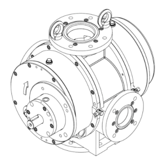
Cooling gas Measuring Measuring Sealing gas used on the connection connection, connection, connections Fore-vacuum Okta 500 G/GM intake side pressure side flange ANSI (150 lbs) 4" 2.5 " G 3/8" G 3/8" 4 x G 1/8" DN 100 PN 10 DN 65 PN 10 G 3/8"... - Page 12 Sealing gas connection Cooling gas connection 100 Sight glass Fig. 3: Roots pump Okta 500 G Vacuum flange Measuring connection Fore-vacuum flange Lubricant filler screw (2x) Sealing gas connection Cooling gas connection 100 Sight glass Fig.
-
Page 13: Range Of Application
Product description Vacuum flange Fore-vacuum flange Cooling gas connection Suction chamber Gas cooler Main rotor Slave rotor Fig. 5: Scheme with gas cooler and cold gas circulation pipe Cooling (option) The (usually) water-cooled gas cooler must be positioned at the gas outlet port of the pump. -
Page 14: Installation
NOTICE Use approved operating fluids only! The use of operating fluids that have not been approved by Pfeiffer Vacuum shall result in a limited warranty. In such cases, it is not possible to guarantee that product-specific performance data will be achieved. - Page 15 Installation max. min. 335.2 335.1 335.1 Fig. 6: Filling with lubricant Screw in lubricant filler screws 335. Check lubricant level when the pump is running at operating temperature in final vac- uum: – Fill level during operation: as per the sight glass image. –...
- Page 16 Installation Cooling the mechanical seal The ambient temperatures to which the pump is exposed will vary depending on the lo- cation in which it is being used. If the cooling of the sealant (max. +90 °C) is not sufficient for the amount of heat radiated at the sealant reservoir, then an additional water cooling system (25) will need to be connected.
-
Page 17: Connecting The Vacuum Side
Installation Connecting the vacuum side WARNING Exposed, rotating rolling pistons! Fingers and hands can become crushed when the intake flange is open. Keep all body parts out of operating range of the rolling pistons. Use a wooden handle to rotate the rolling pistons during cleaning. ... -
Page 18: Connecting A Gas Cooler (Optional)
These can be adapted by the operator or ordered from Pfeiffer Vacuum. The dimensioning of the cold gas recirculation line (7.1) should also be matched to the gas cooler and the pump. - Page 19 Installation Requirements for the cooling water Min. oxygen content 4 mg/kg Max. chloride content 100 mg/kg Max. carbonate hardness for the water temperatures 15 ... 25 °C 10 ° dH 30 ... 40 °C 6° dH Max. potassium permanganate usage 10 mg/kg pH value 7 ...
-
Page 20: Temperature Monitoring (Option)
Installation Installing the pres- The pumps can be effectively protected against failure of the cooling water system by installing a cooling water pressure monitor. sure monitor (op- tional) Assembly Refer to the installation instructions provided by the manufacturer. Set switching pressures; set pressure as excess gauge pressure relative to atmo- spheric pressure: –... -
Page 21: Connecting To The Mains Power Supply
Installation Connecting to the mains power supply The pumps are supplied with three-phase motors for different voltages and frequencies. The applicable motor type is shown on its rating plate. DANGER Voltage-bearing elements Danger to life from electric shock. The electrical connection can be carried out only by trained and authorised electri- cians. - Page 22 Installation W2 U2 U1 V1 Fig. 11: Motor coil and connecting plate of Star Connection (for high voltage) Visual inspection of the direction of rotation Check the direction of rotation of the pump after switching on for the first time: –...
- Page 23 Installation Control voltage OFF button ON button RESET button, external Contactor F1 - F3 F1 ... F4 Fuses T1... T3 PTC resistor sensor Tripping indicator Motor, 3-phase Only for devices with two relay outputs AC 220 ... 240 V Only for MSR type Only for order no.: P 4768 051 FQ T1...T3...
-
Page 24: Connecting Accessories
Installation Connecting accessories The following accessories are not included in the delivery, and can be ordered separate- Sealing gas connec- The evacuation of high-boiling media (e.g. solvents) can be damaging to the lubricant. Damage can be avoided by letting in sealing gas (process-specifically) into the shaft pas- tion sageways between the operating chamber and the gear chamber. -
Page 25: Operation
Operation Operation Before switching on Check lubricant levels at both sight glasses and at the oiler as well. Protect the pump sufficiently from taking in contaminants by means of suitable precau- tions (e.g. protective strainer); if necessary, check lubricant regularly or replace at shorter intervals. - Page 26 Operation CAUTION Hot surface! Danger of burns if hot parts are touched. Depending on the operating and ambient con- ditions, the surface temperature of the pump may rise above 100 °C. In this case, use suitable finger guards. Adjusting the amount Depending on the operating pressure, the empirical value for the supplied sealing gas amount is between 1% (for a high operating pressure) and 8% (for a lower operating of sealing gas...
-
Page 27: Switching Off
2.0 l/min Okta 3000/4000 G 1.5 l/min Okta 1000/1500 G 1.0 l/min Okta 500 G 0.5 l/min NOTICE High pressures are generated in the working chamber of the pump! Exceeding the specified flushing quantities can lead to destruction of the pump. - Page 28 Operation Switch off the pump. Venting should be performed via the suction side, do not ventilate vacuum chambers through the pump. Stop flushing gas feed. Stop cooling water supply. Switching back on After switching off the pump it can be switched back on again within 5 minutes. If you wait any longer then leave the pump to cool to ambient temperature before switching back on again.
-
Page 29: Maintenance
Maintenance Maintenance Precautions WARNING Exposed, rotating rolling pistons! Fingers and hands can become crushed when the intake flange is open. Keep all body parts out of operating range of the rolling pistons. Use a wooden handle to rotate the rolling pistons during cleaning. WARNING Pump parts may be contaminated from pumped media! Danger of poisoning due to contact with harmful substances. -
Page 30: Changing The Lubricant
Checklist for inspec- Certain maintenance and overhaul work should only be performed by Pfeiffer Vacuum Service (PV). Pfeiffer Vacuum will be released from all warranty and liability claims if the tion, maintenance required, below listed, intervals are exceeded or maintenance or overhaul procedures and overhaul are not performed properly. - Page 31 Fill with new lubricant and check fill level. Screw in lubricant filler screws 335. Request safety data sheets for operating fluids and lubricants from Pfeiffer Vacuum or download at www.pfeiffer-vacuum.com. Dispose of operating fluid according to the local regulations. Change sealing oil It is recommended that the sealing oil should be changed on an annual basis.
-
Page 32: Cleaning The Suction Chamber
Maintenance Cleaning the suction chamber WARNING Exposed, rotating rolling pistons! Fingers and hands can become crushed when the intake flange is open. Keep all body parts out of operating range of the rolling pistons. Use a wooden handle to rotate the rolling pistons during cleaning. NOTICE Risk of damage to the pump! During the flushing and cleaning procedure the flushing liquid and the process medium... -
Page 33: Assembling The Motor And Coupling
Maintenance Assembling the motor and coupling WARNING Exposed, rotating coupling! Items of clothing could be trapped and wound up. When mounting the motor, always ensure a correct seating of the coupling protection. Wear close-fitting clothing. Installing the cou- When performing installation work on the coupling, it is important to observe the instal- lation instructions of the coupling manufacturer: pling... - Page 34 Maintenance NOTICE Danger of bursting when the motor is removed! The separating can of the magnetic coupling is made of plastic or ceramics, and can be destroyed when the motor is pulled off. Suspend the motor at the eyebolt to the lifting device and pull it off horizontally. ...
-
Page 35: Decommissioning
Replace the lubricant. Replace bearings. Follow the maintenance instructions and inform Pfeiffer Vacuum. Check pump for visible damage and only start up if it is in the correct condition. If drying pearls were inserted then they should be removed now. -
Page 36: Malfunctions
Repair leak Operational loss of lubricant at the Check and replace radial shaft seals or me- shaft or mechanical seal chanical seal; contact Pfeiffer Vacuum Ser- vice if necessary Unusual operating Suction chamber dirty Switch off pump directly and clean suction... - Page 37 NOTICE Service work should be carried out by a qualified person only! Pfeiffer Vacuum is not liable for any damage to the pump resulting from work carried out improperly. Take advantage of our service training programs; additional information at www.pfei- ffer-vacuum.com.
-
Page 38: Service
The following steps are necessary to ensure a fast, smooth servicing process: Download the forms "Service Request" and "Declaration on Contamination". Fill out the "Service Request" form and send it by fax or e-mail to your Pfeiffer Vacuum service address. -
Page 39: Spare Parts
Please state all information on the rating plate when ordering spare parts. Other spare parts than those described in this manual must not be used without the agreement of Pfeiffer Vacuum. Set of seals for pumps with mechanical sealant (mechanical seal separately) This set of seals includes all of the seal parts such as O-rings, flat seals and square washers. -
Page 40: Accessories
Okta 500 G Splinter shield for Okta 500/500 M/500 G PP 030 149 AX Further detailed accessories are contained in the Pfeiffer Vacuum printed or Online Cat- alogue. 12.1 Documentation for accessories Depending on the pump version, supplementary information may be required for safe... - Page 41 Technical data and dimensions 13.2 Technical data Okta 500 G/GM Parameter Okta 500 G Flange (in) DN 100 ISO-F Flange (out) DN 100 ISO-F Cooling gas connection DN 63 ISO-F Nominal pumping speed 210-630 m Nominal pumping speed at 50 Hz...
- Page 42 M16 (4x) ø ø A ( 1 : 5 ) Dichtrille Vakuumflansch Vorvakuumflansch Innen-Ø118 DIN, DN100 DIN, DN100 Außen-Ø130,8 mit Rille Tiefe 3,6 ø 14 (4x) Fußbohrungen M16 (8x) M16 (8x) ø ø ø ø Fig. 18: Okta 500 G...
- Page 43 Technical data and dimensions ANSI 2.1/2" Dichtrille/sealing groove Innen-/inner ø mit Rille/ Außen-outer ø 90,8 with groove Tiefe/depth 3,6 5/8-11 UNC (4X ) ø 139,7 ø 177,8 Ø14 (4x) Fußbohrungen/ fixing holes A ( 1 : 5 ) Dichtrille/sealing groove Vakuumflansch/vacuum flange Innen-/inner ø...
- Page 44 ● Electromagnetic Compatibility 2014/30/EU ● Restriction of the use of certain Hazardous Substances 2011/65/EU The agent responsible for compiling the technical documentation is Mr. Sebastian Ober- beck, Pfeiffer Vacuum GmbH, Berliner Straße 43, 35614 Aßlar. OktaLine™ Plus Okta 500 G/GM...
- Page 45 VACUUM SOLUTIONS FROM A SINGLE SOURCE Pfeiffer Vacuum stands for innovative and custom vacuum solutions worldwide, technological perfection, competent advice and reliable service. COMPLETE RANGE OF PRODUCTS From a single component to complex systems: We are the only supplier of vacuum technology that provides a complete product portfolio.
Need help?
Do you have a question about the OKTA 500 G and is the answer not in the manual?
Questions and answers