Table of Contents
Advertisement
Quick Links
ITV2-TF2Z363EN
ORIGINAL INSTRUCTIONS
Instruction Manual
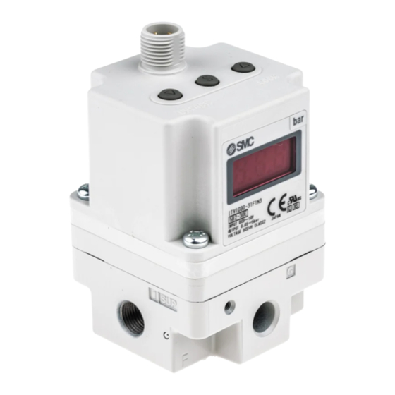
Electro-Pneumatic Regulator
16 point Preset input type
ITV*0*0-5****** Series
3
1
The intended use of the electro-pneumatic regulator is to control the flow
and pressure of fluid in response to preset input signals.
1 Safety Instructions
These safety instructions are intended to prevent hazardous situations
and/or equipment damage. These instructions indicate the level of
potential hazard with the labels of "Caution," "Warning" or "Danger."
They are all important notes for safety and must be followed in addition
*1)
to International Standards (ISO/IEC)
, and other safety regulations.
*1)
ISO 4414: Pneumatic fluid power - General rules relating to systems.
ISO 4413: Hydraulic fluid power - General rules relating to systems.
IEC 60204-1: Safety of machinery - Electrical equipment of machines.
(Part 1: General requirements)
ISO 10218-1: Robots and robotic devices - Safety requirements for
industrial robots - Part 1: Robots.
Refer to product catalogue, Operation Manual and Handling
Precautions for SMC Products for additional information.
Keep this manual in a safe place for future reference.
Caution indicates a hazard with a low level of risk which, if
Caution
not avoided, could result in minor or moderate injury.
Warning indicates a hazard with a medium level of risk
Warning
which, if not avoided, could result in death or serious injury.
Danger indicates a hazard with a high level of risk which, if
Danger
not avoided, will result in death or serious injury.
Warning
Always ensure compliance with relevant safety laws and
standards.
All work must be carried out in a safe manner by a qualified person in
compliance with applicable national regulations.
This product is class A equipment intended for use in an industrial
environment. There may be potential difficulties in ensuring
electromagnetic compatibility in other environments due to conducted
or radiated disturbances.
Caution
Ensure that the air supply system is filtered to 5 microns.
Refer to the SMC website (URL:
https//www.smcworld.com)
information about Safety Instructions.
2 Specifications
2.1 General specifications
Model
ITV*010
Min. supply
(Set pressure) + 0.1 MPa
pressure
Max. supply
0.2 MPa
pressure
0.005 to
Set pressure range
0.1 MPa
Supply voltage
24 VDC ± 10%,
Current
0.12 A or less
consumption
Input signal
16 points (no common polarity)
2
Approx. 4.7 kΩ
Input impedance
NPN – Open collector: 30 V 80 mA
Output signal
PNP – Open collector: 80 mA
Linearity
±1% F.S. or less
Hysteresis
0.5% F.S. or less
Repeatability
±0.5% F.S. or less
Sensitivity
0.2% F.S. or less
Temperature
±0.12% F.S. / °C or less
characteristics
Ambient and fluid
0 to 50°C (no condensation)
temperature
Accuracy
Pressure
MPa: 0.001 / kgf/cm
display
Min. unit
psi: 0.1
Enclosure rating
Main unit: IP65, Cable connector: IP67
Note 1) 1 PSI is the minimum display unit on the ITV*050.
2.2 Size / Weight specifications
Model
ITV10*0
Size (mm)
50×50×109
Weight (no options)
250 g
Warning
Special products (-X) might have specifications different from those
shown in this section. Contact SMC for specific drawings.
3 Installation
3.1 Installation
Warning
Do not install the product unless the safety instructions have been read
and understood.
This product is pre-set at the factory and must not be dismantled by
the user. Contact your local SMC office for advice.
Ensure, when installing this product, that it is kept clear of power lines
for more
to avoid noise interference.
Ensure that load surge protection is fitted when inductive loads are
present (i.e. solenoid, relay etc.).
3.2 Environment
Warning
Do not use in an environment where corrosive gases, chemicals, salt
water or steam are present.
Do not use in an explosive atmosphere.
Do not expose to direct sunlight. Use a suitable protective cover.
Do not install in a location subject to vibration or impact. Check the
product specifications.
Do not mount in a location exposed to radiant heat.
3 Installation (continued)
3.3 Piping
ITV*030
ITV*050
Before piping make sure to clean up chips, cutting oil, dust etc.
When installing piping or fittings, ensure sealant material does not
enter inside the port. When using seal tape, leave 1 thread exposed
1.0 MPa
on the end of the pipe/fitting.
Tighten fittings to the specified tightening torque.
0.005 to
0.005 to
0.5 MPa
0.9 MPa
3.4 Lubrication
Do not use a lubricator on the input side of this product. If lubrication
is required, place the lubricator on the 'output' side so that it does not
enter the product.
SMC products have been lubricated for life at manufacture, and do not
require lubrication in service.
If a lubricant is to be used in the system, refer to the catalogue for
details.
±3% F.S
2
: 0.01 / bar: 0.01,
Note 1)
/ kPa: 1
4 Wiring
ITV20*0
ITV30*0
50×50×131
66×66×152
Connect the cable to the connector on the main unit as shown in the
350 g
645 g
following diagram. Take precautions, as incorrect wiring will damage the
unit. Use a DC power supply capable of supplying the necessary power
requirements with minimal ripple.
4.1 Power supply connector
Item
Connector for
power supply
4.2 Signal connector
Item
1
Connector for
input signal
2
Note: Wire colours shown are when the optional cable is used.
Vs: Power
Supply
24 VDC
(no polarity)
5 Settings
Caution
Turn OFF the power supply before setting the switches.
When the 'SET' key is operated the minimum / maximum pressure will
5.1 Setting Procedure
Release 'Key Lock 'as explained in section 'Key-Lock Function'
After releasing key lock, press the 'Set' key again to move to F-1
Caution
To set the minimum pressure (display shows F-1) use up/down keys
To set the maximum pressure (display shows F-2) use up/down keys
5.2 Key-Lock function
5.3 Error Display
If an abnormality is detected by the ITV the LED display will show 'Er'
Caution
followed by a code number. Isolate the power supply and ascertain the
problem and solve. Re-instate the power supply after correcting any fault.
Error codes are as shown in the table below.
Pin assignment
Wire colour
1. +24V
Brown
4
1
2. F.G.
White
3. GND
Blue
2
3
5.4 Reset function
4. N.C.
-
Press the 'Up' and 'Down' keys together for 3 seconds or more.
Display shows 'RES'.
Release keys to reset minimum pressure and maximum pressure.
Pin assignment
Wire colour
5.5 Zero-clear function
1. Input 0 bit (S0)
Brown
Press the 'Set' keys together for 2 seconds or more.
4
2. Input 1 bit (S1)
White
Press the 'Up' and 'Down' keys. Display shows 'F03'.
3
Press the 'Set' keys. Display shows 'OcL'(Flashing).
3. Input 2 bit (S2)
Blue
Press the 'Up' and 'Down' keys together. Display shows 'Ocl'.
4. Input 3 bit (S3)
Black
5
Press the 'Up' and 'Down' keys together for 3 seconds or more. Display
5. Input common
Grey
Zero-clear is complete.
5.6 Initialization
Press the 'Set' key together for 2 seconds or more.
Press the 'Up' and 'Down' keys. Display shows 'F99'.
Press the 'Set' keys. Display shows 'ini' (flashing).
Press the 'Up' and 'Down' keys together. Display shows 'ini'.
Press the 'Up' and 'Down' keys together for 5 seconds or more. Display
Grey
Initialization is complete.
Caution
be present at the outlet port. When primary pressure is applied to the
regulator minimum pressure will be present at the outlet port.
and press the 'Set' key to 'Lock' the setting.
and press the 'Set' key to 'Lock' the setting.
Note 1: If the above sequence has been followed correctly, the settings
will complete automatically.
Note 2: If only setting minimum pressure, when pressure is 'Set',
pressing the set button once more will 'skip' to the next step.
The keys will be locked and cannot be operated when the power is
supplied. 'Loc' is displayed when any keys are pushed.
Key-Lock Release
Press the 'Down' key for 2 seconds or more.
Display will flash 'Loc' (locked).
Press the 'Set' key to unlock.
Note: To cancel press the 'Up' key.
Key-Lock
Press the 'Up' key for 2 seconds or more.
Display will flash 'unL' (unlocked).
Press the 'Set' key to lock.
Note: To cancel press the 'Down' key.
No
Content
Display
2
EEProm read / write error
Er 2
3
Memory read / write error
Er 3
4
Solenoid valve fault
Er 4
5
Switch output over-current
Er 5
6
Outside of the Zero-clear range
Er 6
shows 'clr' (1second).
Turns OFF (1 second).
Page 1 of 2
Advertisement
Table of Contents

Related Manuals for SMC Networks ITV Series


Summary of Contents for SMC Networks ITV Series
- Page 1 ITV2-TF2Z363EN 2 Specifications 3 Installation (continued) 5 Settings ORIGINAL INSTRUCTIONS 2.1 General specifications 3.3 Piping Caution Caution Model ITV*010 ITV*030 ITV*050 Turn OFF the power supply before setting the switches. Instruction Manual Before piping make sure to clean up chips, cutting oil, dust etc. Min.
- Page 2 ITV2-TF2Z363EN 6 Input state for Preset pressures Preset pressure 7 How to Order Refer to the operation manual or catalogue on the SMC website (URL: http// www.smcworld.com) for How to order information. 8 Outline Dimensions Refer to the operation manual or catalogue on the SMC website (URL: http// www.smcworld.com) for outline dimensions.
Need help?
Do you have a question about the ITV Series and is the answer not in the manual?
Questions and answers