Table of Contents
Advertisement
Quick Links
RS-232 Baud Rate Converter
CE
Model 232BRC
Documentation Number 232BRC-3903
(pn5104-r003)
International Headquarters
B&B Electronics Mfg. Co. Inc.
707 Dayton Road -- P.O. Box 1040 -- Ottawa, IL 61350 USA
Phone (815) 433-5100 -- General Fax (815) 433-5105
Home Page: www.bb-elec.com
Sales e-mail:
orders@bb-elec.com
-- Fax (815) 433-5109
Technical Support e-mail:
support@bb-elec.com
-- Fax (815) 433-5104
European Headquarters
B&B Electronics Ltd.
Westlink Commercial Park, Oranmore, Co. Galway, Ireland
Phone +353 91 792444 -- Fax +353 91 792445
Home Page: www.bb-europe.com
Sales e-mail:
orders@bb-europe.com
Technical Support e-mail:
support@bb-europe.com
B&B Electronics – Revised October 2003
232BRC-3903 Manual
Cover Page
B&B Electronics Mfg Co Inc – 707 Dayton Rd - PO Box 1040 - Ottawa IL 61350 - Ph 815-433-5100 - Fax 815-433-5104
B&B Electronics Ltd – Westlink Commercial Park – Oranmore, Galway, Ireland – Ph +353 91 792444 – Fax +353 91 792445
Advertisement
Table of Contents

Related Manuals for B&B Electronics RS-232 Baud Rate Converter CE 232BRC


Summary of Contents for B&B Electronics RS-232 Baud Rate Converter CE 232BRC
- Page 1 RS-232 Baud Rate Converter Model 232BRC Documentation Number 232BRC-3903 (pn5104-r003) International Headquarters B&B Electronics Mfg. Co. Inc. 707 Dayton Road -- P.O. Box 1040 -- Ottawa, IL 61350 USA Phone (815) 433-5100 -- General Fax (815) 433-5105 Home Page: www.bb-elec.com Sales e-mail: orders@bb-elec.com -- Fax (815) 433-5109...
-
Page 2: Table Of Contents
TABLE OF CONTENTS Chapter 1: INTRODUCTION... 3 Applications ... 3 Specifications ... 4 Default Parameters ... 4 Checklist... 5 Chapter 2: OPERATION ... 7 Port Configurations... 7 Port Connections... 9 LED Indicators... 11 Chapter 3: SETUP SOFTWARE... 13 Introduction... 13 Connection ... -
Page 3: Chapter 1: Introduction
Chapter 1: INTRODUCTION The 232BRC acts as a translator between devices with incompatible asynchronous serial communications. Each port uses a dedicated UART and includes a 16 kbyte receive buffer. Each port can be independently configured for data rate, data format, and handshaking. -
Page 4: Checklist
Checklist Examine the shipping carton and contents for physical damage. If damage is found, file a claim with the shipper immediately. The following equipment should be in the shipping carton: 1. RS-232 Baud Rate Converter model 232BRC 2. Instruction Manual 3. -
Page 5: Chapter 2: Operation
Chapter 2: OPERATION Each port receives data from its connected device, buffers the data, and sends it out the opposite port when that port’s handshaking indicates it is ready to receive data. Each port is set to match the requirements of its connected device through the setup software. -
Page 6: Port Connections
Software(XON/XOFF) Handshaking: Each port can be independently configured for software handshaking. Software handshaking is normally used in communications links where the main data stream is one way, such as to a printer. The main sending device is expected to hold off its data when it receives the XOFF(13 Hex) character, and resume sending when it receives an XON(11 Hex). -
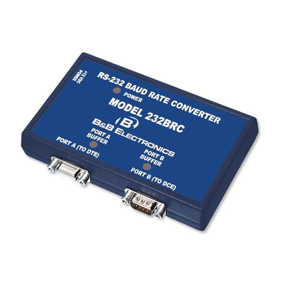
Page 7: Led Indicators
LED Indicators The 232BRC has three LED indicators. The first, labeled “POWER” indicates that power is applied to the converter. The other two, labeled “PORT A BUFFER” and “PORT B BUFFER” indicate that data is present in that port’s receive buffer. Note that the buffer LEDs indicate buffered data only. -
Page 8: Chapter 3: Setup Software
Chapter 3: SETUP SOFTWARE Introduction The 232BRC comes with simple setup software for configuring the A and B ports. The software can run on any PC compatible computer using Microsoft Windows 95, 98, NT, or 2000 operating system. Once the ports are configured, all parameters are saved in non- volatile memory so the 232BRC can be powered down and used anywhere without the loss of configuration data. -
Page 9: Setup Tutorial
Setup Tutorial Step 1: Start the software by double clicking the 232BRC Setup icon on the desktop. Step 2: Select the serial (COM) port that will be used to configure the 232BRC. Step 3: Connect the 232BRC Port A to the PC COM port selected. Install the setup jumper, and power up the 232BRC. -
Page 10: Final System Installation
Step 4: Connect the 232BRC to be copied to the serial (COM) port of the PC. Install the setup jumper. Apply power to the 232BRC. Step 5: Click Next. Step 6: Select Save As from the File menu. Save the configuration to disk. -
Page 11: Appendix A: Cable Charts
Appendix A: Cable Charts All charts give full pinouts. Only pins 2 & 3 are required for basic operation. Pins 7 and 8 are needed for hardware (RTS/CTS) handshaking. If the connected device requires DTR or DSR, these signals are available on pins 4 and 6 respectively. See Appendix B for a block diagram of the 232BRC. - Page 12 Chart A.6. DCE (Modem) DB25 Connector to Port B (DTE) DCE (Modem) 232BRC Serial Port Signal Port B (DTE) DB25 Connector Direction DB9M Connector <----------- -----------> <----------- 7 (RTS) ----------> 8 (CTS) ----------> 6 (DSR) <---------> 5 (GND) <----------- 4 (DTR) Chart A.7.
-
Page 13: Appendix B: Block Diagram
Appendix B: Block Diagram EEPROM Microcontroller UART UART 3 2 7 8 4 6 5 3 2 7 8 4 6 5 PORT A PORT B Female DB9 Male DB9 232BRC Block Diagram 232BRC-3903 Manual Appendix B B&B Electronics Mfg Co Inc – 707 Dayton Rd - PO Box 1040 - Ottawa IL 61350 - Ph 815-433-5100 - Fax 815-433-5104 B&B Electronics Ltd –... -
Page 14: Appendix C: Declaration Of Conformity
Appendix C: Declaration of Conformity DECLARATION OF CONFORMITY Manufacturer’s Name: B&B Electronics Manufacturing Company Manufacturer’s Address: P.O. Box 1040 707 Dayton Road Ottawa, IL 61350 USA Model Number: 232BRC Description: RS-232 Baud Rate Converter Type: Light industrial ITE equipment Application of Council Directive: 89/336/EEC Standards: EN 55022...
Need help?
Do you have a question about the RS-232 Baud Rate Converter CE 232BRC and is the answer not in the manual?
Questions and answers