Advertisement
Available languages
Available languages
Quick Links
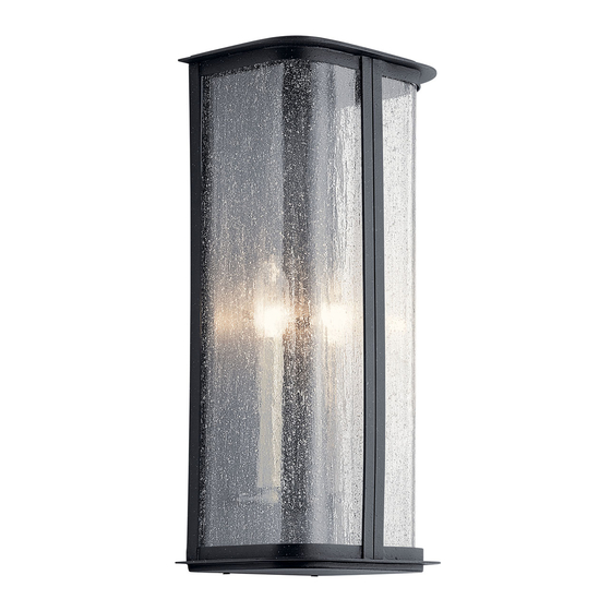
Fixture Diagram
G
I
F
Parts List
[A] Mounting
[D] Mounting
Strap
[B] Outlet Box
[E] Frame
[C] Mounting
[F] Knobs
Strap Screws
[G] Top Cover
Cautions
CAUTION – RISK OF SHOCK –
Disconnect Power at the main circuit breaker panel or main
fusebox before starting and during the installation.
WARNING:
This fixture is intended for installation in accordance
with the National Electrical Code (NEC) and all local code
specifications. If you are not familiar with code requirements,
installation by a certified electrician is recommended.
INSTRUCTIONS FOR MOUNTING FIXTURE OUTDOORS
AND/OR IN WET LOCATIONS:
1) Mounting surface should be clean, dry, flat and 1/4"
larger than the canopy on all sides. Any gaps between the
mounting surface and canopy exceeding 3/16" should be
corrected as required.
2) With silicone caulking compound, caulk completely around
where back of canopy meets the wall surface to prevent
water from seeping into outlet box.
CLEANING:
• Always be certain that electric current is turned off before
cleaning.
• Only a soft damp cloth should be used. Harsh cleaning
products may damage the finish.
REV 18-MAR-2021
H
E
C
A
D
B
[H] Countersunk
Screws
Screws
[I] Glass
For warranty information please visit: kichler.com/warranty
We're here to help
Installation Instructions
1) Find the appropriate threaded holes on mounting
strap[A] that align with hole distance in frame[E].
Thread mounting screws[D] into threaded holes of
mounting strap starting from outlet box[B] side. Attach
the mounting strap to the outlet box using the mounting
strap screws[C].
2) Grounding instructions (See Illus. a or b):
a) On fixtures where mounting strap is provided with a
hole and two raised dimples, wrap ground wire from
outlet box around green ground screw, and thread
into hole.
b) On fixtures where a cupped washer is provided,
attach ground wire from outlet box under cupped
washer and green ground screw, and thread into
mounting strap.
If fixture is provided with ground wire, connect fixture
ground wire to outlet box ground wire with wire
connector after following the above steps. Never connect
ground wire to black or white power supply wires.
a
OUTLET BOX
GROUND
FIXTURE
GROUND
DIMPLES
GREEN GROUND
SCREW
3) Make wire connections. Reference chart below for
correct connections and wire accordingly.
Connect Black or Red
Supply Wire to:
Black
*Parallel cord (round &
smooth)
Clear, Brown, Gold or
Black without Tracer
Insulated wire (other
than green) with copper
conductor
*Note: When parallel wire (SPT
1 & SPT 2) are used. The neutral
wire is square shaped or ridged
and the other wire will be round
in shape or smooth
(see illus.)
4) Push fixture to wall over the mounting screws[D]
protruding from the mounting strap[A]. Be sure not to
pinch wires between wall and frame of fixture.
5) Screw on the two (2) knobs[F] to the frame[E] to secure
fixture to wall.
6) Insert recommended bulb(s) [Not supplied].
7) Carefully lower glass[I] into frame[E], making sure glass
slides between frame and angle bracket attached to
frame.
8) Apply silicone caulking compound completely around
seam between back edge of frame and mounting surface
once fixture is secured to surface.
9) Place top cover[G] on frame and attach using two (2)
countersunk screws[H]. Tighten screws to secure top in
place.
NOTE: DO NOT apply silicone caulking compound around
the seam between the top cover and the frame.
866-558-5706
Hrs: M-F 9am to 5pm EST
WIRE CONNECTOR
OUTLET BOX
GROUND
GREEN GROUND
SCREW
Connect White Supply
Wire to:
White
*Parallel cord (square &
ridged)
Clear, Brown, Gold or Black
with Tracer
Insulated wire (other
than green) with silver
conductor
Neutral Wire
b
FIXTURE
GROUND
CUPPED
WASHER
IS-59090-US
Advertisement

Subscribe to Our Youtube Channel
Related Manuals for Kichler Lighting TIMMIN


Summary of Contents for Kichler Lighting TIMMIN
- Page 1 866-558-5706 We’re here to help Hrs: M-F 9am to 5pm EST Fixture Diagram Installation Instructions 1) Find the appropriate threaded holes on mounting strap[A] that align with hole distance in frame[E]. Thread mounting screws[D] into threaded holes of mounting strap starting from outlet box[B] side. Attach the mounting strap to the outlet box using the mounting strap screws[C].
- Page 2 866-558-5706 INSTRUCTIONS: Nous sommes là pour vous aider For Assembling and Installing Fixtures in Canada Heures : du lundi au vendredi, de 9h à 17h (heure de l’Est) Pour L’assemblage et L’installation Au Canada Diagramme d’appareils Instructions d’installation 1) Localisez les trous taraudés appropriés, sur l’étrier de montage[A] qui s’alignent sur la distance de trou dans le structure[E].
- Page 3 866-558-5706 Estamos aquí para ayudarle Horario: Lunes-Viernes 9am a 5pm EST (hora oficial del este) Diagrama de Accesorios Instrucciones de Instalación 1) Encuentre los orificios roscados apropiados en la abrazadera de montaje[A] que se alineen con la distancia de los orificios en la armazón[E]. Enrosque los tornillos de montaje[D] en los orificios roscados de la abrazadera de montaje empezando por el lado de la caja de conexiones[B].
Need help?
Do you have a question about the TIMMIN and is the answer not in the manual?
Questions and answers