Advertisement
Available languages
Available languages
Quick Links
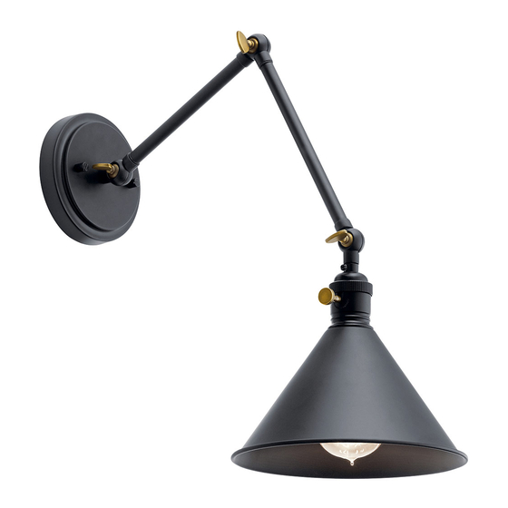
Fixture Diagram
M
P
L
B
E
O
C
D
B
A
E
Q
F
Parts List
[A] Mounting Strap
[G] Fixture
[B] Fixture Mounting
[H] Lockwashers
Screws
[I] Ball Knobs
[C] Outlet Box
[J] Shade
[D] Strap Mounting
[K] Shade Retainer
Screws
[L] Wall Mounting
[E] Strain Relief
[F] Finial
[M] Wall Mounting Plate
Cautions
CAUTION – RISK OF SHOCK –
Disconnect Power at the main circuit breaker panel or main fusebox before
starting and during the installation.
WARNING:
This fixture is intended for installation in accordance with the National Electrical
Code (NEC) and all local code specifications. If you are not familiar with code
requirements, installation by a certified electrician is recommended.
G
I
H
N
R
J
VIEW "A"
K
Q
G
I
H
N
J
R
VIEW "B"
K
[N] Lower Tube
[O] Wire Nuts
[P] Plastic Drywall
Sleeves
[Q] Cord
[R] Screw
Screws
[S] Socket
[T] Switch
Installation Instructions
To mount with cord and without electrical box - VIEW "A"
1) Find a suitable location on the wall to mount your fixture. This location
should be within 7 feet of an electrical outlet.
2) Using wall mounting plate[M] in a horizontal position, mark the two (2) hole
locations for the wall mounting screws. Drill the .187 inch diameter holes and
insert the two (2) plastic drywall sleeves[P]
3) Assemble fixture mounting screws[B] into the appropriate threaded holes of
the wall mounting plate. Mount the wall mounting plate to the wall using the
two (2) wall mounting screws[L].
4) Push fixture[G] to wall carefully over the fixture mounting screws protruding
T
from the wall mounting plate. NOTE: Take care not to pinch the wires
S
between the wall and the canopy of the fixture. Secure fixture into place
using the two lockwashers[H] and two ball knobs[I].
5) Retrieve the shade[J] and the shade retainer[K]. Raise the shade into place
over the socket[S], and secure shade into place with the shade retainer by
threading shade retainer onto the socket.
6) Adjust the fixture arms by slightly loosening the wing nuts at each joint.
CAUTION: Do not remove the wing nuts from the joints.
7) Insert recommended bulb (not supplied).
8) Plug cord[Q] into 120V electrical outlet.
9) Turn on the light by using the turn switch[T] on the socket above the shade.
To mount without cord to electrical box - VIEW "B"
1) Find the appropriate threaded holes on mounting strap[A]. Assemble fixture
mounting screws[B] into threaded holes.
2) Attach mounting strap to outlet box[C] using the strap mounting screws[D].
The mounting strap can be adjusted to suit position of fixture.
3) Loosen the screw[R] in the lower tube[N]. In the canopy, pull approximately
eight inches of the SPT wires (the cord)[Q] up into the canopy, then cut off
the rest of the cord.
4) Slide the strain relief[E] off of the cord and remove the 6 inch tube[N] (by
unscrewing it from the fixture). Remove the cut-off portion of cord.
T
5) Screw on the finial[F] in place of the tube[N].
6) Split the SPT wires 3 inches (76.2mm) and strip the ends of the wires .50 inch
S
(12.7mm).
7) Grounding instructions: (See Illus. a or b).
a) On fixtures where mounting strap is provided with a hole and two raised
dimples, wrap ground wire from outlet box around green ground screw,
and thread into hole.
b) On fixtures where a cupped washer is provided, attach ground wire from
outlet box under cupped washer and green ground screw, then thread
into mounting strap.
If fixture is provided with ground wire, connect fixture ground wire to outlet
box ground wire with wire connector after following the above steps. Never
connect ground wire to black or white power supply wires.
a
WIRE CONNECTOR
OUTLET BOX
GROUND
FIXTURE
GROUND
DIMPLES
GREEN GROUND
SCREW
8) Make wire connections using wire nuts[O]. Reference chart below for correct
connections and wire accordingly.
Connect Black or Red
Supply Wire to:
Black
*Parallel cord (round &
smooth)
Clear, Brown, Gold or
Black without Tracer
Insulated wire (other
than green) with copper
conductor
*Note: When parallel wire (SPT
1 & SPT 2) are used. The neutral
wire is square shaped or ridged
and the other wire will be round
in shape or smooth (See illus.)
9) Push fixture[G] to wall carefully over the fixture mounting screws protruding
from the mounting strap. NOTE: Take care not to pinch the wires between
the wall and the canopy. Secure into place using the two lockwashers[H] and
two ball knobs[I].
10) Retrieve the shade[J] and the shade retainer[K]. Raise the shade into place
over the socket[S], and secure shade into place with the shade retainer by
threading shade retainer onto the socket.
11) Adjust the fixture arms by slightly loosening the wing nuts at each joint.
CAUTION: Do not remove the wing nuts from the joints.
12) Insert recommended bulb (not supplied).
13) Turn on the light by using the turn switch[T] on the socket above the shade.
866-558-5706
We're here to help
Hrs: M-F 9am to 5pm EST
b
FIXTURE
GROUND
OUTLET BOX
GROUND
CUPPED
GREEN GROUND
SCREW
WASHER
Connect White Supply
Wire to:
White
*Parallel cord (square &
ridged)
Clear, Brown, Gold or Black
with Tracer
Insulated wire (other
than green) with silver
conductor
Neutral Wire
IS-43115-US
Advertisement

Related Manuals for Kichler Lighting Ellerbeck 1 Light


Summary of Contents for Kichler Lighting Ellerbeck 1 Light
- Page 1 866-558-5706 We’re here to help Hrs: M-F 9am to 5pm EST Fixture Diagram Installation Instructions To mount with cord and without electrical box - VIEW “A” 1) Find a suitable location on the wall to mount your fixture. This location should be within 7 feet of an electrical outlet.
- Page 2 866-558-5706 INSTRUCTIONS: Nous sommes là pour vous aider For Assembling and Installing Fixtures in Canada Heures : du lundi au vendredi, de 9h à 17h (heure de l’Est) Pour L’assemblage et L’installation Au Canada Diagramme d’appareils Instructions d’installation Pour une installation avec cordon et sans boîtier électrique - VUE «...
- Page 3 866-558-5706 Estamos aquí para ayudarle Horario: Lunes-Viernes 9am a 5pm EST (hora oficial del este) Diagrama de Accesorios Instrucciones de Instalación Para montar con cable y sin caja eléctrica - VISTA “A” 1) Encuentre un lugar adecuado en la pared para montar su artefacto. Esta ubicación debe estar a menos de 7 pies de una toma de corriente.
Need help?
Do you have a question about the Ellerbeck 1 Light and is the answer not in the manual?
Questions and answers