
Related Manuals for Kichler Lighting EYRIE


Summary of Contents for Kichler Lighting EYRIE
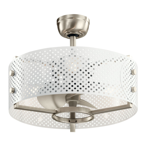
- Page 1 13" EYRIE Product images may vary slightly from actual product. INSTRUCTION MANUAL...
-
Page 3: Table Of Contents
INSTALLING THE LED LAMPS.......... 14 SAFETY RULES................4 INSTALLING THE BATTERIES..........TOOLS REQUIRED..............OPERATING INSTRUCTIONS..........PACKAGE CONTENTS............. INSTALLING THE WALL CONTROL MOUNTING OPTIONS............. SYSTEM WALL PLATE............HANGING THE FAN..............OPERATION INSTRUCTIONS..........INSTALLATION OF SAFETY SUPPORT......TROUBLESHOOTING............. ELECTRICAL CONNECTIONS..........FINISHING THE INSTALLATION........13" EYRIE... -
Page 4: Safety Rules
SAFETY RULES CAUTION-RISK OF FIRE CONSULT A QUALIFIED ELECTRICIAN 8. To avoid personal injury or damage to the fan and other items, be TO ENSURE CORRECT BRANCH CIRCUIT CONDUCTOR. cautious when working around or cleaning the fan. 1. To reduce the risk of electric shock, insure electricity has been 9. -
Page 5: Tools Required
Receiver g. Wall Transmitter h. Part bag contents 1) Mounting hardware: wood screws (2), flat washers (2), star washers (2), lock washers (2), wire nuts (3), screws (2) 2) Safety cable hardware: wood screw, spring washer, flat washer 13" EYRIE... -
Page 6: Mounting Options
MOUNTING OPTIONS If there isn't an existing UL (cUL for Canadian Installation) listed mounting box, then read the following instructions. Disconnect the power by removing fuses or turning off circuit breakers. Secure the outlet box directly to the building structure. Use appropriate fasteners and building materials. -
Page 7: Hanging The Fan
Step 5. Remove the hanger ball from the downrod assembly by Fig. 6 loosening the set screw, unscrewing and removing the cross pin and unscrewing the ball off the rod. (Fig. 7) Hanger ball Set screw Downrod Fig. 7 13" EYRIE... - Page 8 HANGING THE FAN (continued) Supply wires Step 6. Loosen the two set screws and remove the hitch pin and Downrod retaining clip from the coupling on top of the motor assembly. (Fig. Set screws Set screws Hitch pin Retaining clip Step 7.
- Page 9 WARNING: Failure to reattach the cross pin and seat the "Check Tab" can cause the fan to fall from the ceiling during operation. Take special care to make sure this pin is reattached. Fig. 9 Registration slot Fig. 10 13" EYRIE...
-
Page 10: Installation Of Safety Support
INSTALLATION OF SAFETY SUPPORT (required for Canadian installation ONLY) A safety support cable is provided to help prevent the ceiling fan from falling. Step 1. Attach the provided wood screw and washers to the ceiling Ceiling mounting joist next to the mounting bracket but do not tighten. (Fig. 11) Attach bracket safety cable... -
Page 11: Electrical Connections
(Fig. 13) For best bracket performance, make sure the Black Antenna, on the end of the receiver, remains extended and not tangled with any of the electrical wires. Fig. 13 13" EYRIE | 11... - Page 12 ELECTRICAL CONNECTIONS (continued) Outlet box Step 2. Motor to Receiver Electrical Connections: (Fig. 14) Connect the White (neutral) Black (hot) black wire from the fan to the black wire marked "TO MOTOR L" on Green or bare copper (ground) the receiver. Connect the white wire from the fan to the white wire Black ("AC IN L") marked "TO MOTOR N"...
-
Page 13: Finishing The Installation
"Registration Slot" on the side of the hanger ball before attaching the canopy to the bracket. Failure to properly seat the "Check Tab" could damage the electrical wires when to ceiling fan blade direction is changed while the fan is running. 13" EYRIE | 13... -
Page 14: Installing The Led Lamps
INSTALLING THE LED LAMPS NOTE: Before starting installation, disconnect the power by turning off the circuit breaker or removing the fuse at fuse box. Install 4, 7 Watt, E-26 LED lamps (included). Reverse switch 7W LED lamps Fig. 16 14 | KICHLER.COM... -
Page 15: Installing The Batteries
Press and release either button to turn the light ON or OFF. This control system is NOT designed to "Reverse" the rotation of the blades. To set the fan blades in reverse, the reverse slide switch is located on the top of the motor housing. Fig. 18 13" EYRIE | 15... -
Page 16: System Wall Plate
INSTALLING THE BASIC FUNCTION Outlet box Switch WALL CONTROL SYSTEM WALL Wall plate PLATE Select a location to install the Basic Function Wall Control System Transmitter and Wall Plate. Install the wall plate using an existing wall switch outlet box. Make sure the electrical power is TURNED OFF at the main panel before continuing. -
Page 17: Operation Instructions
Cool weather - Reverse (clockwise) An upward airflow moves warm Fig. 22 air off the ceiling area as shown in Fig. 23. This allows you to set your heating unit on a cooler setting without affecting your comfort. Reverse switch Fig. 23 Fig. 21 13" EYRIE | 17... -
Page 18: Troubleshooting
TROUBLESHOOTING Problem Solution Fan will not start. 1. Check circuit fuses or breakers. 2. Check all electrical connections to insure proper contact. CAUTION: Make sure the main power is OFF when checking any electrical connection. Fan sounds noisy. 1. Make sure all motor housing screws are snug. 2. - Page 19 www.kichler.com KICHLER® LIGHTING 7711 EAST PLEASANT VALLEY ROAD P.O. BOX 318010 CLEVELAND, OHIO 44131-8010 CUSTOMER SERVICE 866.558.5706 8:30 AM TO 5:00 PM EST, MONDAY - FRIDAY...
- Page 20 13 " EYRIE™ Les images du produit peuvent différer légèrement du produit réel. MANUEL D'INSTRUCTIONS...
- Page 22 MODE D'EMPLOI..............CONTENU DU COLIS............. INSTALLATION DE LA PLAQUE MURALE OPTIONS DE MONTAGE............DU SYSTÈME DE COMMANDE MURALE ....SUSPENDRE LE VENTILATEUR........INSTRUCTIONS D'UTILISATION........INSTALLATION DU SUPPORT DE SÉCURITÉ... DÉPANNAGE................CONNECTIONS ELECTRIQUES........FIN DE L'INSTALLATION............13 " EYRIE™ | 3...
-
Page 23: Les Règles De Sécurité
LES RÈGLES DE SÉCURITÉ MISE EN GARDE - RISQUE D'INCENDIE CONSULTER UN 8. Pour éviter des blessures ou des dommages au ventilateur et à d’autres ÉLECTRICIEN QUALIFIÉ POUR ASSURER UN CONDUCTEUR DE objets, soyez prudent lorsque vous travaillez ou nettoyez le ventilateur. CIRCUIT DE BRANCHE APPROPRIÉ. -
Page 24: Outils Nécessaires
1) matériel de montage: vis à bois (2), rondelles plates (2), rondelles en étoile (2), rondelles-freins (2), écrous à fil (3), vis (2) 2) matériel de câble de sécurité: vis à bois, rondelle élastique, rondelle plate 13 " EYRIE™ | 5... -
Page 25: Options De Montage
OPTIONS DE MONTAGE S'il n'y a pas de boîtier de montage répertorié UL (cUL pour les installations au Canada), lisez les instructions suivantes. Déconnectez l'alimentation en retirant les fusibles ou en désactivant les disjoncteurs. Fixez la boîte de sortie directement à la structure du bâtiment. Boîte de sortie Utilisez des fixations et des matériaux de construction appropriés. - Page 26 Vis de réglage retirant la tige transversale et en dévissant la boule de la tige. (Fig. 7) Tige de suspension Fig. 7 13 " EYRIE™ | 7...
-
Page 27: Suspendre Le Ventilateur
Suspendre le ventilateur (suite) Fils d'alimentation Étape 6. Desserrez les deux vis de réglage et retirez la goupille Tige de suspension d’attelage et le clip de fixation de l’accouplement situé au-dessus de l’ensemble du moteur. (Fig. 8) Vis de réglage Vis de réglage Goupille d'attelage Clip de... - Page 28 ATTENTION: Si vous ne ré-attachez pas la goupille transversale Fig. 9 et ne placez pas le "Check Tab", le ventilateur risque de tomber du plafond pendant le fonctionnement. Faites particulièrement attention à ce que cette épingle soit recollée. Fente d'inscription Fig. 10 13 " EYRIE™ | 9...
-
Page 29: Installation Du Support De Sécurité
INSTALLATION DU SUPPORT DE SÉCURITÉ (requis pour l'installation canadienne SEULEMENT) Un câble de sécurité est fourni pour empêcher le ventilateur de plafond de tomber. Étape 1. Fixez la vis à bois et les rondelles fournies à la solive de plafond Support de à... -
Page 30: Connections Electriques
(Fig. 13) Pour de meilleures performances, assurez-vous que l'antenne noire, située à l'extrémité du récepteur, reste étendue et ne soit pas emmêlée avec aucun des fils électriques. Fig. 13 13 " EYRIE™ | 11... - Page 31 CONNEXIONS ÉLECTRIQUES Boîte de sortie (suite) Blanc (neutre) Étape 2. Connexions électriques du moteur au récepteur: (Fig. 14) Noir (chaud) Connectez le fil noir du ventilateur au fil noir marqué "TO MOTOR L" Cuivre vert ou nu (terre) sur le récepteur. Connectez le fil blanc du ventilateur au fil blanc Noir ("AC IN L") marqué...
- Page 32 Si vous ne placez pas correctement le "Check Tab", vous risquez d’endommager les fils électriques lorsque la direction des pales du ventilateur de plafond est modifiée pendant le fonctionnement du ventilateur. 13 " EYRIE™ | 13...
-
Page 33: Installation Des Lampes À Del
INSTALLATION DES LAMPES À LED REMARQUE: Avant de commencer l'installation, débranchez l'alimentation en éteignant le disjoncteur ou en retirant le fusible du boîtier à fusibles. Installez 4 lampes LED E-26 de 7 Watt (incluses). Commutateur inversé Lampes à LED 7W Fig. -
Page 34: Mode D'emploi
Ce système de contrôle n'est PAS conçu pour "inverser" la rotation des pales. Pour régler les pales du ventilateur en marche arrière, l'interrupteur à glissière arrière est situé sur la partie supérieure du boîtier du moteur. Fig. 18 13 " EYRIE™ | 15... -
Page 35: Installation De La Plaque Murale
INSTALLATION DE LA PLAQUE MURALE Boîte de sortie Commutateur DU SYSTÈME DE COMMANDE MURALE plaque murale À FONCTION DE BASE Choisissez un emplacement pour installer l'émetteur et la plaque murale du système de commande murale à fonctions de base. Installez la plaque murale en utilisant un boîtier de prise de commutateur mural existant. - Page 36 éloigne l'air chaud du plafond, comme indiqué sur la Fig. 23. Cela vous permet de régler votre appareil de chauffage sur un réglage plus froid sans nuire à votre confort. Commutateur inversé Fig. 23 Fig. 21 13 " EYRIE™ | 17...
-
Page 37: Dépannage
DÉPANNAGE Problème Solution Le ventilateur ne 1. Vérifiez les fusibles ou les disjoncteurs du circuit. démarre pas. 2. Vérifiez toutes les connexions électriques pour assurer un contact correct. MISE EN GARDE: Assurez-vous que l’alimentation principale est éteinte lors de la vérification de toute connexion électrique. - Page 38 www.kichler.com KICHLER® ÉCLAIRAGE 7711 EAST PLEASANT VALLEY ROAD PO BOX 318010 CLEVELAND, OHIO 44131-8010 SERVICE À LA CLIENTÈLE 866.558.5706 8 H 30 À 17 H, HEURE DE L'EST, DU LUNDI AU VENDREDI...
- Page 39 13 " EYRIE™ Las imágenes del producto pueden variar ligeramente del producto real. MANUAL DE INSTRUCCIONES...
- Page 41 INSTALACIÓN DEL SISTEMA DE CONTROL OPCIONES DE MONTAJE ..........DE PARED PLACA DE PARED ........... COLGANDO EL VENTILADOR .......... INSTRUCCIONES DE OPERACIÓN......... INSTALACIÓN DE SOPORTE DE SEGURIDAD ..SOLUCIÓN DE PROBLEMAS ..........CONEXIONES ELÉCTRICAS..........TERMINANDO LA INSTALACIÓN ........13 " EYRIE™ | 3...
-
Page 42: Reglas De Seguridad
REGLAS DE SEGURIDAD PRECAUCIÓN-RIESGO DE INCENDIO CONSULTAR A UN 8. Para evitar lesiones personales o daños al ventilador y otros elementos, ELECTRICISTA CALIFICADO PARA ASEGURAR EL CONDUCTOR tenga cuidado al trabajar o limpiar el ventilador. CORRECTO DEL CIRCUITO DE LA RAMA. 9. -
Page 43: Herramientas Necesarias
(2), arandelas planas (2), arandelas de estrella (2), arandelas de seguridad (2), tuercas para cables (3), tornillos (2) 2) Hardware de cable de seguridad: tornillo de madera, arandela de resorte, arandela plana 13 " EYRIE™ | 5... -
Page 44: Opciones De Montaje
OPCIONES DE MONTAJE Si no hay una caja de montaje listada UL (cUL para instalación canadiense), lea las siguientes instrucciones. Desconecte la energía quitando los fusibles o apagando los disyuntores. Asegure la caja de salida directamente a la estructura del edificio. Use sujetadores y materiales de construcción apropiados. -
Page 45: Colgando El Ventilador
Paso 5 Retire la bola de suspensión del conjunto de la varilla hacia Bola de abajo aflojando el tornillo de fijación, desenroscando y quitando el suspensión Tornillo de ajuste pasador transversal y desenroscando la bola de la barra. (Fig. 7) Downrod Fig. 7 13 " EYRIE™ | 7... - Page 46 COLGANDO EL VENTILADOR (continuación) Cables de suministro Paso 6. Afloje los dos tornillos de fijación y retire el pasador de Downrod enganche y el clip de retención del acoplamiento en la parte superior del conjunto del motor. (Fig. 8) Tornillos de fijación Tornillos de fijación Pasador de enganche Clip de retención...
- Page 47 ADVERTENCIA: Si no vuelve a colocar el pasador transversal y se asienta la "pestaña de verificación", el ventilador puede caerse del Fig. 9 techo durante el funcionamiento. Tenga especial cuidado para asegurarse de que este pin se vuelva a colocar. Espacio de registro Fig. 10 13 " EYRIE™ | 9...
-
Page 48: Instalación De Soporte De Seguridad
INSTALACIÓN DE SOPORTE DE SEGURIDAD (SOLO para instalación canadiense) Se proporciona un cable de soporte de seguridad para ayudar a evitar que se caiga el ventilador de techo. Paso 1. Fije el tornillo de madera y las arandelas provistos a la viga Soporte de montaje del techo junto al soporte de montaje, pero no apriete. -
Page 49: Conexiones Eléctricas
(Fig. 13) Para un mejor rendimiento, asegúrese de que la Antena Negra, en el extremo del receptor, permanezca extendida y sin enredarse con ninguno de los cables eléctricos. Fig. 13 13 " EYRIE™ | 11... - Page 50 CONEXIONES ELÉCTRICAS (continuación) Caja de salida Blanco (neutro) Paso 2. Conexiones eléctricas del motor al receptor: (Fig. 14) Negro (caliente) Conecte el cable negro del ventilador al cable negro marcado Cobre verde o desnudo (molido) "TO MOTOR L" en el receptor. Conecte el cable blanco del Negro ("AC IN L") ventilador al cable blanco marcado "TO MOTOR N"...
- Page 51 Si no se asienta correctamente la "pestaña de verificación", se podrían dañar los cables eléctricos cuando se cambia la dirección de las aspas del ventilador de techo mientras el ventilador está funcionando. 13 " EYRIE™ | 13...
- Page 52 INSTALANDO LAS LUCES LED NOTA: Antes de comenzar la instalación, desconecte la alimentación apagando el disyuntor o quitando el fusible en la caja de fusibles. Instale 4, 7 vatios, lámparas LED E-26 (incluidas). Interruptor de marcha atrás Lámparas LED de 7W Fig.
-
Page 53: Instalando Las Baterías
Este sistema de control NO está diseñado para "invertir" la rotación de las cuchillas. Para colocar las aspas del ventilador en reversa, el interruptor deslizante de reversa se encuentra en la parte superior de la carcasa del motor. Fig. 18 13 " EYRIE™ | 15... - Page 54 INSTALACIÓN DE LA FUNCIÓN BÁSICA Caja de salida Cambiar SISTEMA DE CONTROL DE PARED placa de pared PLACA DE PARED Seleccione una ubicación para instalar el transmisor del sistema de control de pared de funciones básicas y la placa de pared. Instale la placa de pared usando una caja de salida de interruptor de pared existente.
-
Page 55: Instrucciones De Operación
Un flujo de aire ascendente mueve el aire caliente del área del techo como se muestra en la Fig.23. Esto le permite configurar su unidad de calefacción en una configuración más fresca sin afectar su comodidad. Interruptor de marcha atrás Fig. 23 Fig. 21 13 " EYRIE™ | 17... -
Page 56: Solución De Problemas
SOLUCIÓN DE PROBLEMAS Problema Solución El ventilador 1. Verifique los fusibles o disyuntores del circuito. no arranca. 2. Verifique todas las conexiones eléctricas para asegurar un contacto adecuado. PRECAUCIÓN: Asegúrese de que la alimentación principal esté APAGADA cuando verifique cualquier conexión eléctrica. El ventilador 1. - Page 57 www.kichler.com ILUMINACIÓN KICHLER® 7711 EAST PLEASANT VALLEY ROAD PO BOX 318010 CLEVELAND, OHIO 44131-8010 SERVICIO AL CLIENTE 866.558.5706 8:30 AM A 5:00 PM EST, LUNES - VIERNES...
Need help?
Do you have a question about the EYRIE and is the answer not in the manual?
Questions and answers