Advertisement
Quick Links
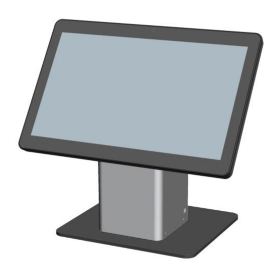
ASSEMBLY INSTRUCTIONS, SLIM SELF-SERVICE STAND
E514693
E514881
E515260
ASSEMBLY INSTRUCTIONS, SLIM SELF-SERVICE STAND
ELO-SELF-SERV-STAND-SLIM-COUNTERTOP
ELO-SELF-SERV-STAND-SLIM-FLOOR-TOP
ELO-SELF-SERV-STAND-SLIM-FLOOR-BASE
© Copyright 2019 Elo Touch Solutions, Inc.
1
Advertisement

Summary of Contents for Elo TouchSystems E514693
- Page 1 ASSEMBLY INSTRUCTIONS, SLIM SELF-SERVICE STAND E514693 ELO-SELF-SERV-STAND-SLIM-COUNTERTOP E514881 ELO-SELF-SERV-STAND-SLIM-FLOOR-TOP E515260 ELO-SELF-SERV-STAND-SLIM-FLOOR-BASE ASSEMBLY INSTRUCTIONS, SLIM SELF-SERVICE STAND © Copyright 2019 Elo Touch Solutions, Inc.
- Page 2 Contents for Kit: E514693 ELO-SELF-SERV-STAND-SLIM-COUNTERTOP Screws / Mounting hardware SCREW, M4X8L, PAN-HEAD, Qty.8 CROSS-RECESS SCREW, M4X6L, PAN-HEAD, Qty.4 CROSS-RECESS SCREW, M4X18L, PAN-HEAD, Qty.4 CROSS-RECESS Tie-wrap SCREW, M4X12L, PAN-HEAD, Qty. 2 Qty.4 CROSS-RECESS Head Assembly Qty. 1 Panel Hardware SCREW, M6X14, PAN-HEAD, CROSS- Qty.2...
- Page 3 Contents for Kit: E514881, ELO-SELF-SERV-STAND-SLIM-FLOOR-TOP Screws / Mounting hardware SCREW, M4X8L, PAN-HEAD, Qty.8 CROSS-RECESS SCREW, M4X6L, PAN-HEAD, Qty.4 CROSS-RECESS Straps Qty. 1 SCREW, M4X18L, PAN-HEAD, Bag M Qty.4 CROSS-RECESS SCREW, M4X12L, PAN-HEAD, Qty.4 CROSS-RECESS SCREW M5X12 FLAT HEAD, Qty.6 CROSS-RECESS, BLACK Tie-wrap Qty.
- Page 4 Contents for Kit: E515260 ELO-SELF-SERV-STAND-SLIM-FLOOR-BASE Base plate Qty. 1 ASSEMBLY INSTRUCTIONS, SLIM SELF-SERVICE STAND © Copyright 2019 Elo Touch Solutions, Inc.
- Page 5 Remove and save (4) screws from stand with provided hex wrench, pull off rear cover. Attach head to counter top plate using (4) screws from bag “I”. For Floor Stand, skip to step For Countertop Stand, continue to step ASSEMBLY INSTRUCTIONS, SLIM SELF-SERVICE STAND ©...
- Page 6 Android Landscape (For Portrait, go to step Top Landscape Tie-wrap cables here as needed. Cable direction Assemble the display to top slotted holes Add (2) screws from bag “L” to top VESA on stand. Add additional (2) screws from positions. Leave ~3mm (1/8”) gap for mounting bag “L”...
- Page 7 Android Portrait Top Portrait Cable direction Tie-wrap cables here as needed. Add (2) screws from bag “L” to top VESA positions. Leave ~3mm (1/8”) gap for mounting to display bracket. Assemble the display to top slotted holes on stand. Add additional (2) screws from bag “L” to bottom VESA mount holes to secure the display.
- Page 8 Windows Landscape (For Portrait, go to step 9) 15” Landscape 22” Landscape Tie-wrap cables Tie-wrap cables here as needed. here as needed. Assemble the display to top slotted holes 15”: add (2) screws from bag “M” to top 75mm VESA positions. on stand.
- Page 9 Windows Portrait 15” Portrait 15” Portrait 22” Portrait Tie-wrap cables here as needed. Assemble the display to top slotted holes on stand. 15”: add (2) screws from bag “M” to top 75mm VESA positions. Add additional (2) screws from bag “L” to bottom 22”: add (2) screws from bag “N”...
- Page 10 22” Portrait Tie-wrap cables here as needed. Route cables through bottom of stand. Attach back cover using screws saved from step 1. Assemble the display to top slotted holes on stand. Add additional (2) screws from bag “L” to bottom VESA mount holes to secure the display.
- Page 11 Remove and save (4) screws on the left and right of the stand tower. Pull off the silver cover and set aside. Add (2) more screws from bag “K” at bottom front of tower. Assemble base plate to tower using Add (2) more screws from bag “K”.
- Page 12 Android Landscape (For Portrait, go to step Top Landscape Tie-wrap cables here as needed. Cable direction Add (2) screws from bag “L” to top VESA positions. Leave ~3mm (1/8”) gap for mounting Assemble the display to top slotted holes on stand. Add additional (2) screws from bag “L”...
- Page 13 Android Portrait Top Portrait Cable direction Tie-wrap cables here as needed. Add (2) screws from bag “L” to top VESA positions. Leave ~3mm (1/8”) gap for mounting to display bracket. Assemble the display to top slotted holes on stand. Add additional (2) screws from bag “L” to bottom VESA mount holes to secure the display.
- Page 14 Windows Landscape 15”/22” Landscape (For Portrait, go to step 20) 15” Landscape 22” Landscape Tie-wrap cables here as needed. Assemble the display to top slotted holes 15”: add (2) screws from bag “M” to top 75mm VESA positions. on stand. Add additional (2) screws from 22”: add (2) screws from bag “N”...
- Page 15 Windows Portrait 15” Portrait 15” Portrait 22” Portrait Tie-wrap cables here as needed. 15”: add (2) screws from bag “M” to top 75mm VESA positions. 22”: add (2) screws from bag “N” to top 100mm VESA positions. Assemble the display to top slotted holes on stand. Add additional (2) screws from bag “L”...
- Page 16 22” Portrait Tie-wrap cables here as needed. Add power brick into tower using provided strap. Route Assemble the display to top slotted holes on stand. additional cables through Add additional (2) screws from bag “L” to bottom base, tower, head as needed. VESA mount holes to secure the display.
- Page 17 Two bolt holes (14mm [0.55”] dia. X2) are available on top of base to secure stand to floor. Feet can be adjusted in case of uneven surfaces. Replace floor stand cover and secure using (4) screws saved from step 6. END for Floor Stand ASSEMBLY INSTRUCTIONS, SLIM SELF-SERVICE STAND ©...


Need help?
Do you have a question about the E514693 and is the answer not in the manual?
Questions and answers