Viavi AVX-10K Operation Manual
Flight line test set
Hide thumbs
Also See for AVX-10K:
- Operation manual (267 pages) ,
- Getting started manual (21 pages) ,
- Getting started manual (17 pages)
Table of Contents
Advertisement
Quick Links
Advertisement
Table of Contents

Related Manuals for Viavi AVX-10K


Summary of Contents for Viavi AVX-10K
- Page 1 AVX-10K Flight Line Test Set Operations Manual...
-
Page 2: Table Of Contents
VNC Viewer ............................ 1 9 2.4. User Interface (UI) Layout .......................... 2 1 2.4.1. General Screen Layout ........................ 2 1 2.4.2. Home Screen Layout ......................... 2 1 2.4.3. Application Screen Layout ......................... 2 2 2.5. UI Header Info and Indicators ........................ 2 2 Rev. 000 2021‐08‐26 22135254 VIAVI CONFIDENTIAL Page 1 of 100 ... - Page 3 ADS‐B Auto .............................. 5 8 4.2.1. Unique Setup ............................. 5 8 4.2.2. Run ADS‐B Auto Test ......................... 5 9 4.3. ADS‐B Monitor ............................ 6 2 4.3.1. Unique Setup ............................. 6 2 Rev. 000 2021‐08‐26 22135254 VIAVI CONFIDENTIAL Page 2 of 100 ...
- Page 4 ELT 406 (Reserved) ............................. 7 6 9. Test Tools ............................ 77 9.1. VSWR ................................. 7 7 9.1.1. VSWR Test Function .......................... 7 7 9.1.2. Scope of VSWR Test ........................... 7 7 9.1.3. UUT Parameters/Characteristics ....................... 7 7 Rev. 000 2021‐08‐26 22135254 VIAVI CONFIDENTIAL Page 3 of 100 ...
- Page 5 Safety and Compliance Information ........................ 9 6 Symbols and Markings ............................ 9 6 Safety Definitions .............................. 9 7 Safety Hazards .............................. 9 8 Toxic Hazards .............................. 9 8 Electrical Hazards .............................. 9 9 Rev. 000 2021‐08‐26 22135254 VIAVI CONFIDENTIAL Page 4 of 100 ...
-
Page 6: Table Of Figures
Figure 13: UI Header Info and Indicators .................... 23 Figure 14: UI Shortcuts Panel ........................ 26 Figure 15: System Settings. ........................ 27 Figure 16: StrataSync™ Update ........................ 37 Figure 17: Antenna Settings. ........................ 42 Figure 18: VSWR Calibration Setup Diagram ..................... 78 Figure 19: VSWR Test Setup Diagram ....................... 81 Figure 20: DTF Test Setup Diagram ...................... 83 Figure 21: System Main Screen ‐ System Menu .................. 86 Rev. 000 2021‐08‐26 22135254 VIAVI CONFIDENTIAL Page 5 of 100 ... -
Page 7: Preface
Preface Purpose and Scope The purpose of this AVX‐10K Flight Line Operations Manual is to help users successfully use the test set features and capabilities. This Operations Manual includes task‐based instructions that describe how to configure and use the AVX‐10K test set. Read this manual carefully before setting up or operating the instrument. Product Nomenclature The following terms may be used in this Operations Manual to refer to the AVX‐10K Flight Line Test Set. AVX‐10K AVX‐10K test set Device Instrument Test Set Intended Audience This Operations Manual is intended for personnel who are familiar with avionic systems, associated equipment, and corresponding terminology. This Operations Manual is intended for novice, intermediate, and experienced users who want to use the AVX‐10K test set effectively and efficiently. Rev. 000 2021‐08‐26 22135254 VIAVI CONFIDENTIAL Page 6 of 100 ... -
Page 8: Related Information
AVX‐10K Operation Related Information Viavi maintains a webpage where additional product information is available to customers: https://www.viavisolutions.com/avx‐10k Use this manual in conjunction with the following information: Getting Started Guide: provides the basics of setup and use. Maintenance Manual: provides guidance for approved maintenance and troubleshooting procedures. Product Brochure: provides ordering information for parts and accessories. Configuration Selection Guide: provides information on configuration details. Data Sheet: provides technical specifications. StrataSync™ User Guide: provides operational information on the StrataSync™ Application Contact Information Contact VIAVI Customer Service for technical support or with any questions regarding this or any other VIAVI products. Phone: 844‐GO‐VIAVI email: AvComm.Service@viavisolutions.com For the latest information, go to: https://www.viavisolutions.com/en/services‐and‐support/support/technical‐assistance Rev. 000 2021‐08‐26 22135254 ... -
Page 9: Overview Avx-10K
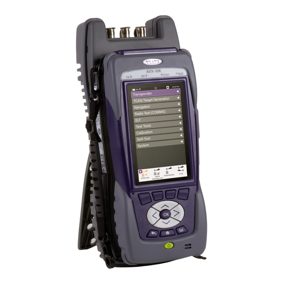
AVX‐10K Operation 1. Overview AVX‐10K 1.1. General Information The AVX‐10K Flight Line Test Set is a portable test instrument that provides a single instrument test solution for performing a variety of flight line testing including Transponder, TCAS, Target Generation, Navigation, Communications (COMMS), and ELT testing. A test tool application is also provided that allows VSWR and Distance to Fault testing for cable and antenna troubleshooting. Figure 1: AVX‐10K Flight Line Operations Test Set The AVX‐10K is supported with two free applications. VIAVI’s Mobile Tech application available from IOS App or Google Play Store, provides remote control via your IOS or Android device as well as technical documentation and training videos. StrataSync™ (available from https://www.viavisolutions.com/en‐us/products/stratasync) is a cloud‐ enabled application supporting asset and test data management. Rev. 000 2021‐08‐26 22135254 VIAVI CONFIDENTIAL Page 8 of 100 ... -
Page 10: Figure 2: Mobile Tech Application
AVX‐10K Operation Figure 2: Mobile Tech Application Figure 3: StrataSync™ Dashboard Rev. 000 2021‐08‐26 22135254 VIAVI CONFIDENTIAL Page 9 of 100 ... -
Page 11: Principles Of Operation
AVX‐10K Operation 1.2. Principles of Operation The AVX‐10K consists of the VIAVI OneExpert base platform and the AVX Application Module. The VIAVI OneExpert base platform supports system functionality such as network connectivity, system updates and power management. The AVX Application Module manages the device’s RF test and measurement functions. Testing with the AVX‐10K can be performed in one of three methods: Direct with Coupler Over‐the‐air using an antenna that can be mounted on the AVX‐10K chassis Directly connected to the UUT. Direct with Coupler Direct to UUT Over the air Figure 4: Operational Test Methods Rev. 000 2021‐08‐26 22135254 VIAVI CONFIDENTIAL Page 10 of 100 ... -
Page 12: Platform And System Features
Platform and System Features The AVX‐10K platform supports the following hardware and system features: Small, rugged design suitable for flight line use Rechargeable, internal battery supports up to 8 hours of typical use A multi‐touch user interface that is similar to those provided on smart devices Bluetooth® and WiFi connectivity supporting both 2.4 GHz and 5 GHz StrataSync™ cloud‐based data collection and asset management application Field upgradeable software and option installation via USB or StrataSync™ Dual Ethernet and 2.0 USB ports WiFi and GPS receivers Smart Access Anywhere ‐ allowing VIAVI tech support to troubleshoot set up and test issues remotely Sleep mode (battery power saving mode) 1.4. Features and Capabilities The AVX‐10K supports testing of the following avionics functions: 1.5. Device Software AVX‐10K ships from the factory with the current version of Software (SW) and Firmware (FW) installed on the Device. Routine maintenance checks should be performed to ensure the Device has been upgraded to the latest production software release. This information is readily available on your StrataSync™ account. In the event a software update is needed, AVX‐10K software can be upgraded in the field using VIAVI's StrataSync™ application (via WiFi or a direct network connection) or by downloading the latest firmware from StrataSync™ to your USB device. ... -
Page 13: Setup, Control, And Operation
AVX‐10K Operation 2. Setup, Control, and Operation 2.1. Control and Operation The AVX‐10K Flight Line Test Set can be operated locally using the touchscreen, keypad or remotely using any mobile device with VIAVI's Mobile Tech application which is available at any online application store. Optionally, remote control of the AVX‐10Kcan be accomplished via a VNC viewing application (such as Tight‐VNC) from a laptop or PC. 2.2. Hardware Figure 5: Front View Rev. 000 2021‐08‐26 22135254 VIAVI CONFIDENTIAL Page 12 of 100 ... -
Page 14: Figure 6: Side View
AVX‐10K Operation Figure 6: Side View Rev. 000 2021‐08‐26 22135254 VIAVI CONFIDENTIAL Page 13 of 100 ... -
Page 15: Controls And Buttons
The device is turned on or off by pressing and holding the button for approximately 3 seconds. When needed, a hard reset is accomplished by pressing and holding the Power button for 10 seconds. Back Button (6) The Back Button is used to exit a menu or to go back to the previous menu or screen. If a data field is selected for editing, selecting the Back Button exits the data field, canceling an un‐confirmed change. Home Button (7) Pressing the Home Button returns to the device’s main/home screen. The UI Home button performs the same action. Tray Button (8) Pressing the Tray Button opens the Utility Tray which contains icons that access base functions that save test reports, turn on/off Bluetooth®, or enable/disable Remote Operation. The Utility Tray can also be opened using the located at the top of the UI. Rev. 000 2021‐08‐26 22135254 VIAVI CONFIDENTIAL Page 14 of 100 ... -
Page 16: I/O Connectors
Navigation Buttons (9) are used to navigate the UI and to open menus and fields on the UI. Function Hard Keys (10) select screen‐specific options or to select menus associated with each key. The Function Hard Keys and UI Function Soft Keys perform the same functions. 2.2.2. I/O Connectors The AVX‐10K is equipped with three TNC‐type connectors on the AVX Application Module. These connectors support test and measurement functions. Figure 7: I/O Connectors Caution: Do not overload input connectors. Refer to the product data sheet for maximum input ratings. SWR Connector The Standing Wave Ratio (SWR) connector is used when performing VSWR and Distance to Fault (DTF) troubleshooting. RF I/O Connector The RF I/O Connector is selectable as the RF Instrument’s (Direct) connect high‐power input/output connector. Rev. 000 2021‐08‐26 22135254 VIAVI CONFIDENTIAL Page 15 of 100 ... -
Page 17: Hand Strap Rings
Hand Strap Rings Four rings are located at the corners of the device and can be used to attach the carry strap. 2.2.4. Status Indicators TX: Transmit Indicator LED blinks green when transmitting to the device under test. RX: Receive Indicator LED blinks green when the AVX‐10K is receiving input from the device under test. Error: This LED is solid red indicates error and alarm conditions. The type of error varies depending on the application. Errors are displayed in the Utility Tray. Batt: multi‐color LED that indicates the battery status. o Solid green indicates that either the battery charge is higher than 30%, or that an external source is powering the unit. o Solid amber indicates that the battery charge is getting low (charge is between 10% and 30%). o Flashing red indicates the device is being powered by external AC Power and the battery is not installed in the device. o Solid red indicates that the battery charge is critically low, less than 10%. An audible beep occurs 30 seconds before shutdown. Charge Status LED: located on the bottom, next to the DC Input connector. The Charge Status LED is a multi‐colored LED that indicates the charge status of the Battery. Rev. 000 2021‐08‐26 22135254 VIAVI CONFIDENTIAL Page 16 of 100 ... -
Page 18: Display Screen
Figure 8: Charge Status LED Solid amber indicates that the battery is charging. Solid green indicates that charging is complete, and the battery is fully charged. Slow flashing red indicates that the battery charge is critically low, less than 10%. Fast flashing red indicates that the charging was suspended due to a fault and user intervention is necessary (for example, the wrong charger is attached). Solid red indicates that the charging was suspended due to overheating. The unit can continue to run, no user intervention necessary. 2.2.5. Display Screen The display screen is a Liquid Crystal Display (LCD). The LCD is a capacitive, touchscreen that operates similar to a smart phone or tablet where you press to open/select/activate, press and hold, press and drag, swipe sideways and pinch to zoom. 2.3. Remote Operation The AVX‐10K test set can be operated remotely via the Mobile Tech application or optionally via a VNC connection using a VNC application running on a computer. Rev. 000 2021‐08‐26 22135254 VIAVI CONFIDENTIAL Page 17 of 100 ... - Page 19 AVX‐10K Operation Mobile Tech application VIAVI’s Mobile Tech app can be found in any mobile device store and can be run from any mobile device. This application can connect to the AVX‐10K via Bluetooth® or WIFI connection. You must have an active StrataSync™ account to access all benefits of the Mobile Tech application. You may also login to the Mobile Tech application as a guest to remotely control the AVX‐10K. The Mobile Tech application also provides access to training videos as well as file access so that you can view test reports from the connected device. Multiple devices can be connected to one AVX‐10K. Once the application is installed and you are able login, the Mobile Tech application will search for nearby connectable devices. Locate the ID of the AVX‐10K that you want to connect to and press the CONNECT button. Once connected, press the Remote Display button and you will be able to view and control the AVX‐10K test set from this device. Rev. 000 2021‐08‐26 22135254 VIAVI CONFIDENTIAL Page 18 of 100 ...
-
Page 20: Vnc Viewer
AVX‐10K Operation 2.3.1. VNC Viewer Establishing a VNC connection with the AVX‐10K test set requires the following: A VNC viewing application must be installed on the computer AVX‐10K test set and computer (both devices must be connected to the same network). Configure the AVX‐10K Remote Operation via Systems Settings using your own VNC password. This will be the password that the user of the VNC viewer software will need in order to gain access. Figure 9: Remote Operation Settings Rev. 000 2021‐08‐26 22135254 VIAVI CONFIDENTIAL Page 19 of 100 ... -
Page 21: Figure 10: Ip Address & Network Id
View the Device UI Remotely 1. Ensure that the AVX‐10K is connected to the internet. 2. Enable VNC capability: a. Open the System Settings Menu. b. Select Remote Operation button. c. Select VNC button. d. Select the Enable VNC Server check box. e. Define VNC password (recommended). Select Back Button to return to previous screen. 3. Launch the VNC viewing application on the computer. 4. Enter the IP address of the test set in the VNC viewer’s server address field and select the OK Button to continue. A password entry box appears. 5. Enter the VNC password (found on the Remote Operation menu) and press the OK Button to submit. The AVX‐10K test set user interface appears in the VNC viewer. Rev. 000 2021‐08‐26 22135254 VIAVI CONFIDENTIAL Page 20 of 100 ... -
Page 22: User Interface (Ui) Layout
AVX‐10K Operation 2.4. User Interface (UI) Layout This section describes the UI screen layout and UI components. 2.4.1. General Screen Layout The device’s UI area consists of a Header Bar and Main Display area. The Header Bar is system defined and appears at the top of every screen. The Display Area updates depending on the screen selected (Home Screen vs Application Screen). 2.4.2. Home Screen Layout The Home Screen contains collapsible menus (or “ribbons”) that expand to provide access to system and test functions. The functions that are available from the Home Screen varies according to the software and hardware options that are enabled on the device. The Header Bar displays system indicators and the Utility Tray Icon which is used to access standard device tools and functions. The Shortcut panel at the bottom of the screen is used to provide quick access to frequently used functions. Figure 11: Home Screen Examples Rev. 000 2021‐08‐26 22135254 VIAVI CONFIDENTIAL Page 21 of 100 ... -
Page 23: Application Screen Layout
AVX‐10K Operation 2.4.3. Application Screen Layout Application screens contain the Header Bar, a main Display Area and a row of Function Soft Keys. Function Soft Keys are selected using the touchscreen or the device’s Function Hard Keys. The content of application screens varies according to the application, but layout is consistent from one application to another. Figure 12: Application Screen Examples 2.5. UI Header Info and Indicators The UI uses the following indicators to show function and system status: Active Connectivity Icons are shown at the top of the screen. When connected to the network via the LAN port, the top indicators will look like this: Rev. 000 2021‐08‐26 22135254 VIAVI CONFIDENTIAL Page 22 of 100 ... -
Page 24: Figure 13: Ui Header Info And Indicators
When connected to WIFI, the top indicators will look like this: Template Name: If a template is being used, this area will reflect the name of the selected template. See Template Management in System settings for more information. Figure 13: UI Header Info and Indicators Battery Status Indicator The Battery Status Indicator displays the charge level of the device’s internal battery. The charge level is also displayed as a percent next to the indicator. AC Power Indicator The AC Power Indicator is displayed when the device is connected to an AC power supply. Network Connection Indicator The Network Connection Indicator is displayed when the device is connected to an active LAN via one of the device’s Ethernet connectors. Rev. 000 2021‐08‐26 22135254 VIAVI CONFIDENTIAL Page 23 of 100 ... - Page 25 The Bluetooth® Indicator is displayed when Bluetooth® mode is enabled on the device. System Error Indicator See “Notifications” for information about the Notifications panel. A red “X” is displayed when the device experiences a critical system error. A system generated error message will also be displayed in the Notification panel. Function and Test Application Status Function and test application icons change color to indicate whether or not the function is current initialized (actively running) on the device. Function Off Function icons are displayed with a white background when the function is inactive (turned off). Function Initialized When a function or application has been initialized, the icon updates to orange with an “X” displayed to the left of the icon. The “X” is used to close the application. Function Running Selecting the Back Arrow will disable or stop the application. Rev. 000 2021‐08‐26 22135254 VIAVI CONFIDENTIAL Page 24 of 100 ...
-
Page 26: Ui Navigation
Entering Alpha/Numeric Data Some parameters are defined using text or numeric entry fields (for example, test settings or user information). The process is similar to data entry on a mobile device. 1. Select (or navigate to) the desired parameter to open the data entry field. A data entry box is displayed. 2. Select (or navigate to) the data entry box. A keypad is displayed on the screen. 3. Use the keypad to enter the data. To switch from letters to numbers, use the button in the lower left (123 or ABC). On the alphabetic keypad, the second key, the up arrow, is the shift key. On the numeric keypad, the second key (1/2) switches between multiple numeric screens. The left pointing arrow with the x in it is the backspace key. 4. Select the enter/return key (the fourth system key) on the screen keypad or press the OK key. The data is entered and stored. Rev. 000 2021‐08‐26 22135254 VIAVI CONFIDENTIAL Page 25 of 100 ... -
Page 27: Managing Application Shortcuts
Select Menu Item Open the menu and select the menu item. When a menu item is selected using the touchscreen, the selection is activated upon selection and the menu closes. < or > Use the arrow navigation keys to highlight the desired item; press the OK button to confirm. When confirmed, the selection is activated and the menu closes. 2.8. Managing Application Shortcuts Figure 14: UI Shortcuts Panel The Home Screen contains an area at the bottom of the screen that can be used to create shortcuts for up to four frequently used applications. To create a shortcut Touch and hold the function icon, drag and drop the icon to the Shortcut panel located at the bottom of the screen. To remove or overwrite a shortcut To remove, touch and hold the application icon in the shortcut panel, drag and drop away from the shortcut panel, or move an application icon to the Shortcut panel placing it over one of the existing shortcuts. Rev. 000 2021‐08‐26 22135254 VIAVI CONFIDENTIAL Page 26 of 100 ... -
Page 28: Configuring System Settings
AVX‐10K Operation 2.9. Configuring System Settings Figure 15: System Settings. Date and Time – Time and Date are driven by having the AVX‐10K connected to an NTP (Network Time Protocol) server. Date and Time formats can be adjusted, and Time Zone set for local time. Use of Daylight Savings time can be toggled on or off as well. Remote Operation – These settings are used to support the connection of remote devices as described in section 2.6. Typically, all settings are left enabled. You can enter a password to be used for VNC viewer connectivity. Bluetooth® –Bluetooth® can be toggled on or off which can also be done from the system tray. This screen will show the name of your device which is used to connect in the Mobile Tech app. All paired devices are shown here as well as their connectivity state. International Settings – Country, Language, Keyboard type, Measurement System, Temperature Units and Time Zone are all settable from this page. USB Software Update – If you need to update software via USB stick, this is the right place. There should only be one software update file on the root drive of the USB stick. Insert a USB stick with the provided or downloaded software update file into either of the USB ports on the Rev. 000 2021‐08‐26 22135254 VIAVI CONFIDENTIAL Page 27 of 100 ... - Page 29 AVX‐10K Operation side of the AVX‐10K. Click the Force Software Update option and then click the Update button in the lower right corner. Hardware and Software Revisions – This is where you go when someone from VIAVI asks what hardware or software revisions your unit has. Software Options – This screen provides a listing of all of the VIAVI software options aligned with the AVX‐10K (and more). This will also reflect the activation level of the respective option (Enabled or Upgradeable). Hardware Options – This screen reflects the ID and Serial Number of the installed GPS Module. Calibrations – Simply shows last calibration date. Position Format Setting – This is a replicated setting from the ADS‐B, GICB, and Traffic (Target Gen) setup screens that allows you to change the Latitude and Longitude format being used. e.g. “DD MM SS.SS”. This setting is globally reflected for all applications. Home Screen – This setting allows for enabling or disabling the top‐level ribbons on the Home Screen. For instance, if you don’t have the ELT software option and you do not need to see it on the Home Screen, toggle ELT to off. Automatic File Purge – Having this option set to ON will help keep the file folders from filling up. This function works in conjunction with StrataSync™ so that whenever files are sent to your StrataSync™ account, they are removed from the AVX‐10K file folder. You can also trigger a manual file purge from here to remove all reports. Save Location – This setting allows you to select where you want report files to be saved. They can be saved locally to the AVX‐10K file folders or to a connected USB drive or to both, where applicable. Restore Factory Defaults – Resets all System and Application Settings back to factory defaults and allows for you to selectively delete all files in the file folders and clear international settings. ...
-
Page 30: Establishing Network Connections
Before you establish a connection to an Ethernet or WiFi network, you must enable network connectivity on your instrument. 1. Go to the Tray menu. 2. Press the Network icon. The icon will be green when connectivity is enabled. Network connectivity is enabled. 2.10.1. Establish Ethernet Connection You must have an Ethernet LAN cable to establish an Ethernet connection to your instrument. Using an Ethernet cable, connect the instrument to the LAN: Connect one end of the Ethernet cable to the AVX‐10K Ethernet connector located on the side panel and connect the other end of the Ethernet cable to the LAN. Verify that network connectivity is enabled. Go to the System menu, then press Network. The System Network menu appears. Select the Ethernet button at the bottom of the menu. Items appear that allow you to specify settings that are required to connect to the LAN. Select Network Mode and then specify the network mode: IPv4, IPv6, or IPv4/ IPv6 Dual Stack. Depending on the Network Mode, you have one or more additional settings to specify. Configure the instrument’s IP settings to match the LAN settings by doing one of the following: If you specified IPv4 as your network mode, specify the following settings: IPv4 Address Mode DHCP Use Vendor ID – Enter your Vendor ID if your network requires a Vendor ID. Use User Class – Enter your User Class if your network requires a User Class Use Arp Announce – If required, enable Arp Announce to have the instrument do the Arp announce after the DHCP request. Rev. 000 2021‐08‐26 22135254 VIAVI CONFIDENTIAL Page 29 of 100 ... - Page 31 Static IPv4 Address – Enter the instrument’s IP address. IPv4 Netmask – Enter the netmask address to indicate whether the packets are to be routed to other networks or sub‐networks. IPv4 Gateway – Enter the address for the gateway that is used to route packets that are not on the same subnet. IPv4 DNS Server – Enter the address of the DNS server. Shared – Share the IP from another interface (for the multi‐interface mode). If you specified IPv6 as your network mode, specify the following settings: IPv6 Address Mode DHCPv6 DHCPv6 Request Type Address – Specify the address. Prefix – Specify the prefix. Stateless IPv6 DNS Address Mode DHCPv6 – No additional settings to specify. Manual – Enter the IPv6 DNS Server address. Static IPv6 Global Address – Enter the instrument’s IPv6 address to access the global network. IPv6 Local Address Manual – Enter the IPv6 Local Address. Automatic – The address is populated automatically. Rev. 000 2021‐08‐26 22135254 VIAVI CONFIDENTIAL Page 30 of 100 ...
-
Page 32: Establishing A Wifi Connection
IPv6 Gateway – Enter the address for the gateway that is used to route packets that are not on the same subnet. IPv6 DNS Address Mode DHCPv6 – No additional settings to specify. Manual – Enter the IPv6 DNS Server address. If you specified IPv4/IPv6 Dual Stack as your network mode, specify the following settings: IPv4 /IPv6 Dual Stack Address Modes Static – See the IPv4 Address Mode in this section. Stateless – See the IPv6 Address Mode in this section. 7. Display the Tray menu, and then press Network to establish the connection. The instrument establishes an Ethernet connection to the LAN. 2.10.2. Establishing a WiFi Connection The WiFi option allows you to establish a WiFi connection to a wireless network to 1) Synchronize your instrument to the StrataSync™ server, 2) Export reports, screenshots (using FTP), or 3) Update the firmware on your instrument. Adding a WiFi Network Profile If an access point does not broadcast its Service Set Identifier (SSID), you can manually create a profile for a WiFi network. Your instrument will save the profile, then automatically authenticate and establish a connection to the network if 1) network connectivity is enabled, 2) the network's access point is in range, and 3) the network is determined to provide the best available access point (based on signal strength and/or encryption supported). Rev. 000 2021‐08‐26 22135254 VIAVI CONFIDENTIAL Page 31 of 100 ... - Page 33 AVX‐10K Operation The instrument can save up to 32 WiFi network profiles. Your instrument will automatically save a profile after successfully connecting to a new WiFi network. 1. Verify that network connectivity is enabled. 2. Go to the System menu, then press Network. The System Network menu appears. 3. Select the WiFi button at the bottom of the menu. Your instrument immediately scans for WiFi networks and lists each network as an item. 4. Press Add Network. The Add WiFi Network menu appears. 5. Specify the following settings: SSID – The SSID (Service Set Identifier) of the WiFi network. Password – The password required to authenticate to the network. A password is not required if Key Management is set to None. Key Management – Open, WEP, or WPA/WPA2 Personal. Network Mode – IPv4, IPv6, or IPv4/IPv6 Dual Stack. Depending on the Network Mode, you have one or more additional settings to specify. For details, see those areas earlier in this section. 6. Return to the System Network menu. The network that you created a profile for is listed on the menu. Rev. 000 2021‐08‐26 22135254 VIAVI CONFIDENTIAL Page 32 of 100 ...
- Page 34 Connecting to a WiFi Connection You can manually connect to any compatible WiFi network that is within range of your instrument, and for which you have authorized access (and a password for authentication). 1. Verify that network connectivity is enabled. 2. Go to System, then press Network. The System Network menu appears. 3. Select the WiFi button at the bottom of the menu. Your instrument immediately scans for WiFi networks and lists each network as an item. • A lock indicates that authentication is required to connect to a network. • Saved, In Range – A profile for the network has been saved on your instrument, and a connection can be established to the instrument. • Saved, Out of Range – A profile for the network has been saved on your instrument, but the network is out of range (and therefore, a connection cannot be established). • Incompatible – A connection cannot be established to a network. • Connected – The instrument has already established a connection to the network. The instrument automatically connects to the network determined to provide the best available access point (based on signal strength and/or encryption supported). 4. If you want to connect to a different network, press the SSID of the WiFi network. A screen appears with items that allow you to specify advanced settings (profile settings), forget a saved network, or connect to the network. 5. Press Connect. • Messages appear briefly indicating the instrument is performing a four‐way handshake, then authenticating to the network. • The status of the connection (Network Up), and details concerning the connection (IP address, netmask, gateway, and DNS server) appears at the top right of the menu. The instrument is connected to the WiFi network. Rev. 000 2021‐08‐26 22135254 VIAVI CONFIDENTIAL Page 33 of 100 ...
-
Page 35: Establishing A Bluetooth Connection
The Bluetooth® panel is displayed. 2. Select the tick box to Enable Bluetooth®. Bluetooth® connectivity is enabled. Connecting to a Bluetooth Device You can establish a connection to any Bluetooth® device that is within range of your instrument, and for which you have authorized access. 1. Go to the System Settings menu, then select Bluetooth®. The Bluetooth® Settings menu appears. 2. Press the box next to Enabled. A checkmark appears. 3. Press Scan for devices. The instrument scans for Bluetooth® devices, then lists the devices on the menu. 4. Select the device to connect. • If the instrument successfully authenticates to the device, a message appears indicating that pairing was successful. • If the instrument does not successfully authenticate to the device, a message appears indicating that pairing failed. If pairing was successful, you can use the instrument with the paired device. 2.10.4. Synchronizing to the StrataSync™ Server StrataSync™ is a hosted, cloud‐based software application that provides VIAVI instruments with access to asset, configuration, and test‐data management functions. StrataSync™ manages inventory, test results and performance data with browser‐based ease and improves technician and instrument efficiency. Rev. 000 2021‐08‐26 22135254 VIAVI CONFIDENTIAL Page 34 of 100 ... - Page 36 Features include the following: Tracking ownership of the AVX‐10K test set Pushing configuration settings (templates) to the AVX‐10K test set Receiving configuration settings from the AVX‐10K test set Adding and/or removing software options on the AVX‐10K test set Updating the software on the AVX‐10K test set Uploading and storing of test reports, screen shots, and configurations To obtain the latest configuration settings, software options and updates, and ownership registration information, the AVX‐10K can synchronize with a VIAVI server via the Internet. The synchronization also stores any user files stored on the unit to the StrataSync™ server. StrataSync™ synchronization should be performed often, as part of the instrument’s operator level maintenance procedures to assure the latest firmware is installed. To establish a StrataSync™ account refer to the Quick Start Guide for additional information and visit https://www.viavisolutions.com/en‐us/products/stratasync and click the REQUEST AN ACCOUNT link. Preliminary Step Obtain or verify server settings with your company's IT organization. Sync with StrataSync™ 1. Specify the user information on the User Info menu. A valid account ID must be entered in order to synchronize with the StrataSync™ server. 2. Open the System menu and select the StrataSync™ button. The StrataSync™ settings menu appears. ...
- Page 37 Upon synchronization with the StrataSync™ server, the device will send the following information to the server: • The device’s serial number. • The device’s hardware information ‐ assemblies and their revision levels. • The device’s MAC address. • The device’s User settings ‐ name (user/technician) and ID. • Software update milestones (includes status and warnings, if applicable) If the configuration information contained on the server is newer than the information on the unit, the server will be considered to be the most up‐to‐date. The server will then send any files to the unit being synchronized that it determines are newer than those on the unit. The device will then send any Reports, Configuration profiles, XML results, screen shots, etc. that have been saved on the unit since the last configuration. The server then applies any applicable Options to the device. If any upgrades are available, the user will be informed of the update availability and offered the choice to upgrade. When synchronization is complete, the Status will indicate “Sync Complete”. The device may be disconnected from the server. Rev. 000 2021‐08‐26 22135254 VIAVI CONFIDENTIAL Page 36 of 100 ...
-
Page 38: Updating Test Set Software
AVX‐10K Operation 2.10.5. Updating Test Set Software StrataSync™ Update Procedure 1. From the StrataSync™ account, select “Update Firmware” from the Assets Menu and click the rocket ship icon next to the version of the software to install. Figure 16: StrataSync™ Update 2. Locate the test set (or test sets) that you would like to update and click the box in the left‐ most column and “YES” on the next screen to proceed. 3. Then from the AVX‐10 test set that has been targeted for update, select the START button from the StrataSync™ page. Follow the prompts to finalize software update. The unit will shutdown after the update is complete. Rev. 000 2021‐08‐26 22135254 VIAVI CONFIDENTIAL Page 37 of 100 ... - Page 39 AVX‐10K Operation USB Update Procedure Navigate to the AVX‐10K product page https://www.viavisolutions.com/en‐us/products/avx‐ 10k‐flight‐line‐test‐set#overview and download software to a USB device. a. Software must be loaded onto a FAT 32 USB Flash Drive. b. Download file to USB device. 2. Connect the AVX‐10K test set to the AC charger adapter to ensure an uninterrupted supply of power during the update. 3. Connect the USB device to one of the AVX‐10K’s test set USB Connectors. The device will auto‐detect the USB drive. 4. Navigate to the USB Software Update page (System Settings > USB Software Update). 5. Select the desired firmware file on the USB drive. 6. Press the Update button to start the upgrade. At prompt, press Update again to confirm. Rev. 000 2021‐08‐26 22135254 VIAVI CONFIDENTIAL Page 38 of 100 ...
-
Page 40: Test Application Common Settings / Steps
AVX‐10K Operation 3. Test Application Common Settings / Steps 3.1. Antenna Setups 3.1.1. Direct with Coupler This is one of the more common test setup methods where the AVX‐10K RF I/O port is cabled to a coupler which is then mounted over or clamped to an antenna. When using this setup, the cable loss as well as the coupler loss must be considered. These values can be entered in the Setup tab. 3.1.2. Over the Air The AVX‐10K can also be used to test the onboard equipment using the over‐the‐air test setup. When using this setup, the antenna gain, the height of the antenna and the distance from the antenna must be considered. These values can also be entered in the Setup tab. The antenna gain values can be found on the label of the antenna. Caution: Testing over‐the‐air with ADS‐B transponder turned on can cause interference with ATC and nearby aircraft. Utilize antenna couples and proper shielding where applicable and refer to SAFO 17002 and follow proper procedures to avoid. Rev. 000 2021‐08‐26 22135254 VIAVI CONFIDENTIAL Page 39 of 100 ... -
Page 41: Direct To Uut
AVX‐10K Operation 3.1.3. Direct to UUT On occasion, the AVX‐10K may need to be directly connected to the UUT bypassing the antenna and cabling. When using this setup, only the cable loss will factor into the setup parameters. 3.2. Common Setup Parameters There are settings that are duplicated across many applications within the AVX‐10K. This section will detail those common settings of applicable test applications from the SETUP tab. These include: “RF Port” (Antenna, Direct Connect, Direct Connect with Coupler) “Antenna Settings” (Range, Height, Gain [1.03 GHz, 1.09 GHz]) “Cable Settings” (Cable Length, Cable Loss) “Coupler Settings” “UUT Address” “Position Settings” (Entry Method, Latitude, Longitude, Format) “Advanced Settings” (Check All UUT Capability, Verify Unit Setup Configuration) Rev. 000 2021‐08‐26 22135254 VIAVI CONFIDENTIAL Page 40 of 100 ... -
Page 42: Rf Port
AVX‐10K Operation All application‐specific settings will be discussed in the associated application sections below. 3.2.1. RF Port There are three methods for any typical test setup: Direct Connect with Coupler (RF I/O), Antenna (over‐the‐air), and Direct Connect. The RF Port setting allows you to select the test method. Rev. 000 2021‐08‐26 22135254 VIAVI CONFIDENTIAL Page 41 of 100 ... -
Page 43: Antenna Settings
AVX‐10K Operation 3.2.2. Antenna Settings When ANTENNA is selected as the RF Port in use, applicable settings will become active. Set Top and Bottom Antenna Range and Height in accordance with the figure below. Values can be selected by scrolling the vertical bar or using the plus and minus keys. Top and Bottom settings are both available only when Diversity Test (an application‐ specific setting) is ON. Otherwise, only Bottom Antenna settings will be available. Figure 17: Antenna Settings. Rev. 000 2021‐08‐26 22135254 VIAVI CONFIDENTIAL Page 42 of 100 ... -
Page 44: Cable Settings
AVX‐10K Operation Set Antenna Gain values for 1030 MHz and 1090 MHz located on the back of the RF flat panel antenna. t 3.2.3. Cable Settings The Cable Settings will be enabled when Direct Connect or Direct Connect with Coupler are selected as the RF Port setting. Setting the Cable Length will drive an estimated cable loss. If exact cable loss is known, entering the value will override the provided estimate. 3.2.4. Coupler Settings Coupler Settings will be enabled if Direct Connect with Coupler is selected as the RF Port setting. Enter the loss of the coupler being used. These values should be listed on the coupler label. Rev. 000 2021‐08‐26 22135254 VIAVI CONFIDENTIAL Page 43 of 100 ... -
Page 45: Uut Address
AVX‐10K Operation 3.2.5. UUT Address For transponder related tests, the Unit Under Test (UUT) Address can be set to Auto or Manual. If set to Manual, you may enter the 6‐character Hexadecimal address of the device being tested. When set to Auto, the test will interrogate the UUT and use the address in the reply as the UUT Address. Note – for the UUT to respond to a MODE S all‐call, the aircraft must be in the airborne condition. Manual mode is used to target a specific aircraft under test when the aircraft under test is being tested while on the ground or in a multi‐path environment. 3.2.6. Position Settings This setting allows you to set the position used for ADS‐B and TCAS related testing. You can select USER ENTRY or VIA GPS RX. The GPS Receiver will allow you to use your local position. If needed, you can obtain your position using the GPS RX functionality of the AVX‐10K. GPS Position Format can be set to be displayed in Degrees, Degrees Minutes, or Degrees Minutes Seconds. Rev. 000 2021‐08‐26 22135254 VIAVI CONFIDENTIAL Page 44 of 100 ... -
Page 46: Advanced Settings
AVX‐10K Operation 3.2.7. Advanced Settings Check All UUT Capability – for Transponder and ADS‐B applications, all test parameters the UUT is capable of will be tested. This is typically always set to Yes. ADS‐B Auto DF Setting – Choose DF17 (typical – for Mode S transponders) or DF18 (1090MHz emitters) Position Decode – Choose Global (most common, decodes two consecutive squitters to determine position) or Local (uses one squitter and entered GPS LAT/LON position to determine position) Verify Unit Setup Configuration – when set to YES, this will cause a pop‐up screen to appear after the RUN button is selected, allowing the user to verify the AVX‐10K is set up correctly prior to running the test. Setting this to NO will disable this popup screen. Rev. 000 2021‐08‐26 22135254 VIAVI CONFIDENTIAL Page 45 of 100 ... -
Page 47: Managing Files / Reports Via Usb And Stratasync
AVX‐10K Operation 3.3. Managing Files / Reports via USB and StrataSync™ 3.3.1. Saving Reports After running a test or collecting monitored information, press SAVE to access the Save Test screen. The Test Name can be overwritten or used as provided and Saved locally by selecting the Save button. The Job ID field is an open comments field that can be used for report filtering and within the StrataSync™ application. Work Order ID is not used for this application. Reports can then be saved onto a USB stick or sync’d with the StrataSync™ application. Rev. 000 2021‐08‐26 22135254 VIAVI CONFIDENTIAL Page 46 of 100 ... -
Page 48: File Management
AVX‐10K Operation 3.3.2. File Management The AVX‐10K file browser is used to open, rename, copy, or delete saved test result files, screen shots, or other files stored on the device. Open the File Browser Expand the System ribbon and select the File Browser icon. Rev. 000 2021‐08‐26 22135254 VIAVI CONFIDENTIAL Page 47 of 100 ... - Page 49 AVX‐10K Operation Use the up and down arrow keys to navigate folders or files. Rev. 000 2021‐08‐26 22135254 VIAVI CONFIDENTIAL Page 48 of 100 ...
- Page 50 AVX‐10K Operation Opening a File or Folder You can open a folder using any of the following: Check the box next to the folder and select Open at the bottom of the page Tap anywhere on the folder field you wish to open Using the up/down arrow keys and the OK button Rev. 000 2021‐08‐26 22135254 VIAVI CONFIDENTIAL Page 49 of 100 ...
- Page 51 AVX‐10K Operation Once opened a list of test results are shown in TXT, html and .json formats. Rev. 000 2021‐08‐26 22135254 VIAVI CONFIDENTIAL Page 50 of 100 ...
- Page 52 AVX‐10K Operation TXT and .json formats can be exported and formatted by users for report generation in supporting programs html format is readable on the device as shown below and as a downloaded file / test report. Note – in the tray there is a View Reports icon where all htlm reports can also easily be viewed on the device. Rev. 000 2021‐08‐26 22135254 VIAVI CONFIDENTIAL Page 51 of 100 ...
- Page 53 Select Copy, navigate to another folder or drive, press the File Options system key, and then select Paste. Select either Copy to USB if you are using File Browser or Copy to Internal if you are using the USB File Browser. 4. The file is copied and the File Browser menu appears. Upload Files 1. Open the File Browser. 2. Select a file or folder. 3. Press the File Options system key, and then select Upload FTP/HTTP. The Upload settings appear. 4. Specify the Upload URL, Username, and Password. 5. Select and press the Apply button to start the upload. When the upload finishes, a message appears stating that the selected files were uploaded. 6. Press OK to close the dialog window. Rev. 000 2021‐08‐26 22135254 VIAVI CONFIDENTIAL Page 52 of 100 ...
-
Page 54: Transponder
AVX‐10K Operation 4. Transponder 4.1. XPDR Auto 4.1.1. Unique Setup Refer to Chapter 3 for common setup items. Setting Definition Diversity (on, off) Set to ‘On’ to test both top and bottom antennas for a diversity system and Diversity Isolation Test Advanced – RAD47 An Australian directive for civil aviation where the reply pulse width is between 0.35 to 0.55 us and amplitude variation (droop) is not greater than 1dB. Set to ON if applicable. 4.1.2. Run Transponder Auto Test With the Transponder AUTO TEST ribbon expanded, you will see that the Test Configuration Box is shaded identifying it as an active field. By selecting this, it will show all available test configurations. Select desired test from the provided list. Rev. 000 2021‐08‐26 22135254 VIAVI CONFIDENTIAL Page 53 of 100 ... - Page 55 AVX‐10K Operation Transponder class and option identification are found on the transponder’s TSO label. Configuration Description FAR Part 43 Runs only the tests associated with FAR Part 43 Appendix F as required by 91‐413 test requirements GENERIC MODE S Tests Mode S transponders, specifically when the class of the transponder is unknown plus this test includes test requirements like EHS/ELS in addition to the FAR Part 43 Appendix F test. GENERIC ATCRBS Tests ATCRBS transponders, specifically when the class of the transponder is unknown. ALTITUDE CHECK Allows for altitude testing for up to 25 altitude settings. MODE S CL A Tests Mode S Class A transponders. MODE S CL B Tests Mode S Class B transponders. MODE S CL B OPT POW Tests Mode S Class B transponders equipped with Class A power option. Rev. 000 2021‐08‐26 22135254 VIAVI CONFIDENTIAL Page 54 of 100 ...
- Page 56 AVX‐10K Operation Configuration Description MODE S CL B OPT FREQ Tests Mode S Class B transponders equipped with Class A frequency tolerance option. ATCRBS CL A Tests ATCRBS Class A transponders. ATCRBS CL B Tests ATCRBS Class B transponders. At the bottom of the page you will see the Test Parametrics button. By selecting this you will see the predefined limits applied to ERP, Frequency and MTL measurements for the test configuration selected. To run a complete test, select the Run button. Once the test completes, the contents of the top summary ribbon will display pass/fail results. Rev. 000 2021‐08‐26 22135254 VIAVI CONFIDENTIAL Page 55 of 100 ...
- Page 57 AVX‐10K Operation If any of the tests fail, you can open the associated ribbon to see the resultant failure. If any of the individual test ribbons are expanded and the Run button is selected, you will be asked if you want to loop on that specific expanded ribbon test, which will also include all expanded ribbons, or run a complete test. The expanded test options are listed below the RUN button. After test completion, you can select the XPDR Config Check button to display specific decoded transponder configuration settings to ensure proper setup of the transponder under test. This is a beneficial tool for user verification of transponder configuration. For transponder configured fields, the AVX‐10K only displays the decoded data and cannot determine PASS/FAIL criteria for these fields. Rev. 000 2021‐08‐26 22135254 VIAVI CONFIDENTIAL Page 56 of 100 ...
-
Page 58: Common Test Results
AVX‐10K Operation 4.1.3. Common Test Results Test Status Indication Description NOT RUN RUN button has not yet been pressed NO REPLY UUT has not yet provided the information. UUT may be in ground state and will not reply to Mode S All Call. Transponders only replies to discrete interrogations when in ground state. NOT CAPABLE Test will not be ran as the UUT is not able to provide this information PASS Test concluded. PASSED. FAIL Test concluded. FAILED. If you choose to save your test results, please refer to Chapter 3 for managing reports. Rev. 000 2021‐08‐26 22135254 VIAVI CONFIDENTIAL Page 57 of 100 ... -
Page 59: Ads-B Auto
AVX‐10K Operation 4.2. ADS‐B Auto 4.2.1. Unique Setup Refer to Chapter 3 for common setup items. Rev. 000 2021‐08‐26 22135254 VIAVI CONFIDENTIAL Page 58 of 100 ... -
Page 60: Run Ads-B Auto Test
Setting Definition Barometric Altitude Set to ‘YES’ and enter test altitude for comparison to transponder Reference reported barometric altitude Test Type Allows selection between AC20‐165 FAA Advisory Circular for testing ADS‐B installed systems and CS‐ACNS applicable EASA requirements Test Type > Aircraft If CS‐ACNS test type is selected, select either 3 NM or 5 NM Separation separation value. Advanced – ADS‐B Choose DF17 (typical – for Mode S transponders) or DF18 (1090MHz Auto DF Setting emitters) Advanced – Position Choose Global (most common, decodes two consecutive squitters to Decode determine position) or Local (uses one squitter and entered GPS LAT/LON position to determine position) 4.2.2. Run ADS‐B Auto Test The ADS‐B Auto test is a combination of Airborne and Surface testing. Once the test setup parameters have been entered, and with the Aircraft under test in the airborne state, move to the Airborne screen, and select the RUN key. Rev. 000 2021‐08‐26 22135254 VIAVI CONFIDENTIAL Page 59 of 100 ... - Page 61 AVX‐10K Operation Once the Airborne tests have completed, move to the Surface screen, set the aircraft under test in the surface mode (weight on wheels) and select the Run button. Rev. 000 2021‐08‐26 22135254 VIAVI CONFIDENTIAL Page 60 of 100 ...
- Page 62 AVX‐10K Operation Once the testing completes successfully, the screens will look similar to this: If you choose to save your test results, please refer to Chapter 3 for managing reports. Rev. 000 2021‐08‐26 22135254 VIAVI CONFIDENTIAL Page 61 of 100 ...
-
Page 63: Ads-B Monitor
4.3. ADS‐B Monitor The AVX‐10K provides flight line test capability for receiving (ADS‐B Monitor mode), decoding and displaying full ADS‐B DO‐260/A/B DF17/DF18 extended squitter transmissions from Mode S transponders or DF18 extended squitters from 1090 MHz emitters. 4.3.1. Unique Setup Refer to Chapter 3 for common setup items. Setting Definition Advance – ADS‐B Choose DF17 (typical – for Mode S transponders) or DF18 Auto DF Setting (1090MHz emitter Advance – Position Choose Global (most common, decodes two consecutive squitters Decode to determine position) or Local (uses one squitter and entered GPS position to determine position) 4.3.2. Run Monitoring To monitor airborne or surface ADS‐B messaging, press the associated tab and press the RUN key. For surface message monitoring, ensure that the test aircraft is in surface mode (weight‐on‐wheels is set to on). Rev. 000 2021‐08‐26 22135254 VIAVI CONFIDENTIAL Page 62 of 100 ... -
Page 64: Gicb
AVX‐10K Operation If you choose to save your results, please refer to Chapter 3 for managing reports. 4.4. GICB GICB mode fully decodes and displays all Enhanced Surveillance BDS register contents. 4.4.1. Unique Setup Refer to Chapter 3 for common setup items. Setting Definition Advance – GICB Choose DF20 or DF21 Downlink Format Advance – Position Choose Global (most common, decodes two consecutive squitters' Decode to determine position) or Local (uses one squitter and entered GPS position to determine position) Rev. 000 2021‐08‐26 22135254 VIAVI CONFIDENTIAL Page 63 of 100 ... -
Page 65: Gibc Monitoring
AVX‐10K Operation 4.4.2. GIBC Monitoring The default mode (Simple Mode) will query for common GICB register values. Toggle the mode by pressing the Simple Mode key and the test set will query for all GICB registers (Adv. Mode). If you choose to save your results, please refer to Chapter 3 for managing and viewing reports. Rev. 000 2021‐08‐26 22135254 VIAVI CONFIDENTIAL Page 64 of 100 ... -
Page 66: Uat Monitoring
AVX‐10K Operation 4.5. UAT Monitoring 4.5.1. Unique Setup Reserved for future use. 4.5.2. Run UAT Monitoring Reserved for future use. Rev. 000 2021‐08‐26 22135254 VIAVI CONFIDENTIAL Page 65 of 100 ... -
Page 67: Tcas / Target Generation
Refer to Chapter 3 for common setup items. The following unique setup parameters are found on the SETUP tab for the TCAS application. Setting Description Test Set Address Enter a 6‐digit Hexadecimal address other than the address of the unit under test. Squitters Toggles between ON and OFF Altitude Reporting Toggles between ON and OFF Display Altitude Toggles between RELATIVE and ABSOLUTE The main screen of the TCAS application also has a number of configurable parameters. These configurable fields have a blue background. Setting Description Allows for selection of predefined scenarios and a provision for Scenario saving custom scenarios. When one of the predefined scenarios are selected, all the following parameters will be loaded with values. TCAS Type Select between TAS, TCAS I or TCAS II to emulate Intruder Type Toggles between ATCRBS and MODE S type of transponder to emulate Range Start (nm) Enter a value between 0 and 260 nautical miles Range Stop (nm) Enter a value between 0 and 260 nautical miles Rev. 000 2021‐08‐26 22135254 VIAVI CONFIDENTIAL Page 66 of 100 ... -
Page 68: Run Tcas Scenario
Description Range Rate (kts) Enter a value between 0 and 1200 knots (closure rate) Reply (%) Enter a value between 0 and 100% for reply rate Rate Enable Toggles between STOP and RESUME Converge Toggles between OFF and ON. Altitude Detect Toggles between OFF and ON. Altitude Rate (fpm) Enter a value between 0 and 10000 feet per minute Altitude Direction Toggles between UP and DOWN Altitude Start Enter a value between ‐1000 and 126700 feet Altitude Stop Enter a value between ‐1000 and 126700 feet Aircraft Baro Test Enter a value between ‐1000 and 126700 feet. This is the altitude of Altitude the UUT. 5.1.2. Run TCAS Scenario This application will allow you to set up one dynamic intruder for TCAS testing. You can select from one of the provided scenarios listed or create one of your own and save it as a custom scenario for later recall. Any of the fields with a blue background are editable. Rev. 000 2021‐08‐26 22135254 VIAVI CONFIDENTIAL Page 67 of 100 ... - Page 69 AVX‐10K Operation Press the RUN button to start generating the scenario. While running the fields with the white background shown here will be updating and will turn to a green background. You can click on the tabs or swipe right to view the additional data. When the intruder type is toggled to ATCRBS as shown below, the SURVEILLANCE and BROADCAST tabs are replaced by the WHISPER/SHOUT tab where you can increase or decrease attenuation by pressing the associated buttons. Rev. 000 2021‐08‐26 22135254 VIAVI CONFIDENTIAL Page 68 of 100 ...
- Page 70 AVX‐10K Operation Rev. 000 2021‐08‐26 22135254 VIAVI CONFIDENTIAL Page 69 of 100 ...
- Page 71 AVX‐10K Operation If you created a new profile, you may choose to save for later use by pressing the Save Profile button, selecting one of the custom fields and then pressing the Save Scenario button. Rev. 000 2021‐08‐26 22135254 VIAVI CONFIDENTIAL Page 70 of 100 ...
-
Page 72: Target Gen
Aircraft Under Test Description Setting Target Type Select between ADS‐B, ADS‐R and TIS‐B ADS‐B Type Toggles between AIRBORNE and SURFACE and only available when Target Type is set to ADS‐B Latitude Set to Latitude of UUT Longitude Set to Longitude of UUT Heading Enter a value between 0 and 359 degrees Altitude Enter a value between ‐1000 and 126700 feet Target Settings (repeated Description for five targets) Flight ID Enter up to eight characters Aircraft Address Enter up to 6 hexadecimal characters Bearing Enter a value between 0 and 359 degrees to define the bearing in relation to the UUT. Range Enter a value between 0 and 40 nautical miles to define the distance from UUT. Rev. 000 2021‐08‐26 22135254 VIAVI CONFIDENTIAL Page 71 of 100 ... -
Page 73: Run Target Gen
AVX‐10K Operation Altitude Enter a value between ‐3500 and 3500 feet to define the vertical distance from the UUT. Altitude Rate Select between CLIMB, LEVEL, DESCEND 5.2.2. Run Target Gen This application will allow you to set up to five static intruders for testing of ADS‐B In Receivers. Any of the fields with a blue background are editable. The data in the Target settings are referenced from the Aircraft Under Test. Each Target can be disabled or enabled by toggling the button. Rev. 000 2021‐08‐26 22135254 VIAVI CONFIDENTIAL Page 72 of 100 ... -
Page 74: Uat Gen (Reserved)
AVX‐10K Operation You may choose to save for later use by pressing the Save/Recall Configuration button, selecting one of the custom fields and then pressing the Save Configuration button. 5.3. UAT GEN (reserved) Rev. 000 2021‐08‐26 22135254 VIAVI CONFIDENTIAL Page 73 of 100 ... -
Page 75: Navigation
AVX‐10K Operation 6. Navigation 6.1. Integrated Landing System (ILS) Operation (Reserved) 6.2. VHF Omnidirectional Ranging (VOR) Operation (Reserved) 6.3. Distance Measuring Equipment (DME) (Reserved) Rev. 000 2021‐08‐26 22135254 VIAVI CONFIDENTIAL Page 74 of 100 ... -
Page 76: Radio Test (Comms)
AVX‐10K Operation 7. Radio Test (COMMS) 7.1. VHF COM Amplitude Modulation (AM) (Reserved) 7.2. VHF COM Frequency Modulation (FM) (Reserved) 7.3. COM High Frequency (HF) Single Side Band (SSB) (Reserved) 7.4. COM SelCal (Reserved) Rev. 000 2021‐08‐26 22135254 VIAVI CONFIDENTIAL Page 75 of 100 ... -
Page 77: Elt
AVX‐10K Operation 8. ELT 8.1. ELT 121.5 (Reserved) 8.2. ELT 243 (Reserved) 8.3. ELT 406 (Reserved) Rev. 000 2021‐08‐26 22135254 VIAVI CONFIDENTIAL Page 76 of 100 ... -
Page 78: Test Tools
9.1.1. VSWR Test Function The VSWR test function provides users with the ability to troubleshoot potential cabling and / or antenna issues. Voltage Standing Wave Ratio (VSWR) is a measurement that represents how well an antenna's impedance is matched to the radio or transmission line to which it is connected. The smaller the VSWR measurement, the better the antenna and transmission line match, and therefore less loss and better signal strength on the transmission line. The minimum VSWR is 1.0, which means no power is being reflected Return loss (RL) is the ratio of the reflected signal to the transmitted signal. A low return loss indicates less signal reflection and better signal strength. A high return loss indicates more signal reflection and less signal strength, indicating an issue along the transmission line. When Return Loss is selected, measurements are displayed in dB. 9.1.2. Scope of VSWR Test This test is used to evaluate how well an antenna's impedance matches the impedance of the radio or transmission line to which it is connected. 9.1.3. UUT Parameters/Characteristics The example in this section assumes the following UUT (Unit Under Test) characteristics and settings. You will need to adjust settings according to the operational capabilities of the device you are testing. In this case, we will be showing a test of a Transponder antenna. Frequency Range Settings: 900 to 1250 MHz Rev. 000 2021‐08‐26 22135254 VIAVI CONFIDENTIAL Page 77 of 100 ... -
Page 79: Equipment Needed For Vswr Test
AVX‐10K Operation 9.1.4. Equipment Needed for VSWR Test The following equipment is required to perform the procedures defined in this section: Cable or antenna to be tested Calibration Kit (short cable with short and load – included with the AVX‐10K) Run VSWR Calibration 1. It is recommended that the VSWR calibration be performed prior to testing any antenna or cable. 2. Connect the short TNC to TNC cable to the AVX‐10K as shown. Figure 18: VSWR Calibration Setup Diagram Rev. 000 2021‐08‐26 22135254 VIAVI CONFIDENTIAL Page 78 of 100 ... - Page 80 AVX‐10K Operation 3. Power on the AVX‐10K. 4. Select the Test Tools ribbon on the Home screen. 5. Select the VSWR/DTF application. 6. Select the VSWR tab. 7. Press the Calibrate soft‐key. 8. Select External Standards. Select OK button to confirm. 9. Follow the instructions at the bottom of each screen to perform Open / Short / Load calibration. The “short” is the smaller of the two terminators. Press SAVE button to complete. Rev. 000 2021‐08‐26 22135254 VIAVI CONFIDENTIAL Page 79 of 100 ...
- Page 81 AVX‐10K Operation 10. When external calibration has been completed, the calibration plot should resemble the following figure. Rev. 000 2021‐08‐26 22135254 VIAVI CONFIDENTIAL Page 80 of 100 ...
-
Page 82: Figure 19: Vswr Test Setup Diagram
AVX‐10K Operation Perform VSWR Test Figure 19: VSWR Test Setup Diagram Configure the AVX-10K for VSWR Test 1. Power on the AVX‐10K. 2. Select the Test Tools ribbon on the Home screen. 3. Select the VSWR/DTF application. 4. Select the VSWR tab. 5. Open the Instrument Settings menu. 6. Set the Start Frequency to 900 MHz. 7. Set the Stop Frequency to 1250 MHz. 8. Open Instrument Settings, set Measurement Mode to VSWR and press the OK button. 9. Ensure the VSWR soft key is set to VSWR On. ... -
Page 83: Distance To Fault
AVX‐10K Operation Review Test Data 1. Observe the VSWR trace. 2. This example shows an antenna that appears to be tuned well for 1030 MHz and 1090 MHz which indicates a good antenna. A poor antenna would have high VSWR values in this band. 9.2. Distance To Fault 9.2.1. DTF Test Function Distance to Fault (DTF) is an analysis that is used to identity signal path degradation in cables and transmission lines that may be a result of conditions such as poor connections, damaged cables, or faulty antennas. Rev. 000 2021‐08‐26 22135254 VIAVI CONFIDENTIAL Page 82 of 100 ... -
Page 84: Scope Of Dft Test
The distance to fault of a coaxial cable. 9.2.3. Equipment Needed for DTF Test The following equipment is required to perform the procedures defined in this section: Cable to be tested TNC adapter if applicable to interface with the AVX‐10K SWR port Perform DTF Test Figure 20: DTF Test Setup Diagram Configure the AVX-10K for DTF Test 1. Power on the AVX‐10K. 2. Select the Test Tools ribbon on the Home screen. 3. Select the VSWR/DTF application. 4. Select the Cable DB tab and select the appropriate cable type (or nearest proximity) for the cable being tested. Rev. 000 2021‐08‐26 22135254 ... - Page 85 AVX‐10K Operation 5. Select the DTF tab. 6. Open the instrument settings menu. 7. Set measurement mode to Return Loss. 8. Open the instrument settings menu and set the stop distance to a distance longer than the cable under test. 9. Close the instrument settings tab and ensure the DTF enable soft key displays DTF on. The AVX‐10K will display the DTF trace. Rev. 000 2021‐08‐26 22135254 VIAVI CONFIDENTIAL Page 84 of 100 ...
- Page 86 AVX‐10K Operation 11. Set the marker to the peak which reflects a fault indication to determine the distance to fault. The markers can be moved manually or using the peak buttons at the bottom of the screen. The middle button is peak find and the adjacent buttons are next peak left or right (if additional peaks exist). Rev. 000 2021‐08‐26 22135254 VIAVI CONFIDENTIAL Page 85 of 100 ...
-
Page 87: System And Utility Functions
AVX‐10K Operation 10. System and Utility Functions 10.1. Introduction System and utility functions configure device parameters such as date and time, network, WiFi and Bluetooth® access. The Test Set contains built‐in signal generators and modulators for XPDR frequencies. System and utility functions also support file management, user setup information and updating the device’s software and firmware. 10.2. System Functions System functions are accessed from the System Menu on the device’s Home Screen. System Settings are discussed in Section 2.12. Figure 21: System Main Screen ‐ System Menu Rev. 000 2021‐08‐26 22135254 VIAVI CONFIDENTIAL Page 86 of 100 ... - Page 88 AVX‐10K Operation StrataSync™ – This application allows for reports to be pushed to the StrataSync™ server. It is recommended that synchronization be performed often to check for firmware updates. Network – You can select between WIFI or hard‐wired connectivity and set all of the associated IP Address settings here. Toggling on and off can be accomplished here as well as from the system tray. Web Browser – This is a web browser. File Browser – Similar to a file browser on a computer. Additionally, you can select files to be copied to an FTP server that you specify. Once a file or group of files is selected, press the File Options button and enter the FTP server URL and associated username and password and click Apply. If a valid FTP connection is made, the files will be transferred. Job Manager – Not used. Diagnostics – Allows a number of diagnostics messaging to be performed. This area is intentionally not fully documented as it is used mainly for troubleshooting purposes. GPS– Allows for User Entry or GPS Module Position Settings. These settings are used globally for associated applications. Rev. 000 2021‐08‐26 22135254 VIAVI CONFIDENTIAL Page 87 of 100 ...
-
Page 89: Battery Replacement
AVX‐10K Operation 11. Battery Replacement Caution: Remove device from AC power supply. To Remove the Battery. Place the test set on a suitable work bench with the display facing down. Loosen but do not fully remove the six flat blade, captive screws that secure the module to the base unit. The screws are identified with the battery symbol. There is no need to remove the eight phillips head screws as the back shell can stay mounted to the module. Rev. 000 2021‐08‐26 22135254 VIAVI CONFIDENTIAL Page 88 of 100 ... - Page 90 AVX‐10K Operation Caution: Remove cover carefully to avoid damaging the PCB assembly and water seal. If module sticks to the base unit, insert a screwdriver where pry slots are provided and gently pry until module releases. Disconnect the module from the base unit while carefully avoiding damage to the PCB assembly. If module sticks to the base unit, insert a screwdriver where pry slots are provided and gently pry until module releases. Rev. 000 2021‐08‐26 22135254 VIAVI CONFIDENTIAL Page 89 of 100 ...
- Page 91 AVX‐10K Operation Loosen the screw that secures the battery cover and remove the cover to expose the battery. Push tab on battery cable connector clip to release and pull cable away from connector. Rev. 000 2021‐08‐26 22135254 VIAVI CONFIDENTIAL Page 90 of 100 ...
- Page 92 AVX‐10K Operation Remove battery from the device. Dispose of the old battery according to local regulations. Rev. 000 2021‐08‐26 22135254 VIAVI CONFIDENTIAL Page 91 of 100 ...
- Page 93 New Battery Installation Procedure WARNING: The battery that came with the device is a Lithium Ion battery. If the battery is not installed correctly it may explode. Use care when installing the battery to ensure the battery is properly inserted in the device. 1. Insert the new battery in the battery compartment. Caution: When installing the new battery, use care to ensure wires are inside the compartment. Damage may occur if wires are pinched by the cover. 2. Align and connect the module to the base unit. Verify the module is flush on the base unit before proceeding. 3. Screw in the six screws to secure the Module Cover to the base unit. 4. Dispose of the old battery according to local regulations. Rev. 000 2021‐08‐26 22135254 VIAVI CONFIDENTIAL Page 92 of 100 ...
-
Page 94: Caveats And Statements
AVX‐10K Operation Appendix A. Caveats and Statements Every effort was made to ensure that the information in this manual was accurate at the time of printing. However, information is subject to change without notice, and VIAVI reserves the right to provide an addendum to this manual with information not available at the time that this manual was created. Copyright/Trademarks Copyright date is a variable set to the current year. If you need to update it (backward or forward), type in the year instead of using the variable. © Copyright 2021 VIAVI Solutions Inc. All rights reserved. No part of this guide may be reproduced or transmitted, electronically or otherwise, without written permission of the publisher. VIAVI Solutions and the VIAVI logo are trademarks of VIAVI Solutions Inc. (“VIAVI”). All other trademarks and registered trademarks are the property of their respective owners. The Bluetooth® word mark and logos are registered trademarks owned by Bluetooth SIG, Inc. and any use of such marks by VIAVI is under license. Reproduction and distribution of this guide is authorized for US Government purposes only. DFARS Statement If software is for use in the performance of a U.S. Government prime contract or subcontract, software is delivered and licensed as “Commercial Computer Software” as defined in DFAR 252.227‐7014 (Feb 2014), or as a “Commercial Item” as defined in FAR 2.101(a) or as “Restricted Computer Software” as defined in FAR 52.227‐19 (Dec 2007) or any equivalent agency regulation or contract clause. Use, duplication or disclosure of Software is subject to VIAVI Solutions' standard commercial license terms, and non‐DOD Departments and Agencies of the U.S. Government will receive no greater than Restricted Rights as defined in FAR 52.227‐19(c)(1‐ 2) (Dec 2007). U.S. Government users will receive no greater than Limited Rights as defined in FAR 52.227‐14 (June 1987) or DFAR 252.227‐7015 (b)(2) (November 1995), as applicable in any technical data. Declaration of Conformity VIAVI recommends keeping a copy of the Declaration of Conformity that shipped with the unit with the device at all times. ... - Page 95 AVX‐10K Operation Terms and conditions Specifications, terms, and conditions are subject to change without notice. The provision of hardware, services, and/or software are subject to VIAVI’s standard terms and conditions, available at www.viavisolutions.com/en/terms‐and‐conditions. Federal Communications Commission (FCC) Notice FCC is specific to the US. If the product is intended to be sold outside North America, include the appropriate Declaration of Conformity with the safety instructions (typically separate ‐ printed ‐ documents). For hardware products only. Consult product manager to verify whether this should be included and compliance engineer to verify content and wording. Delete section for software guides. This product was tested and found to comply with the limits for a Class A digital device, pursuant to Part 15 of the FCC Rules. These limits are designed to provide reasonable protection against harmful interference when the equipment is operated in a commercial environment. This product generates, uses, and can radiate radio frequency energy and, if not installed and used in accordance with the instruction manual, may cause harmful interference to radio communications. Operation of this product in a residential area is likely to cause harmful interference (see section “Electromagnetic Interference (EMI)” on page xii). The authority to operate this product is conditioned by the requirements that no modifications be made to the equipment unless the changes or modifications are expressly approved by VIAVI. Industry Canada Requirements Marketing to determine if this should be included. The IC requirements should always be in both English and French This Class A digital apparatus complies with Canadian ICES‐003. Cet appareil numérique de la classe A est conforme à la norme NMB‐003 du Canada.Cet appareil numérique de la classe A est conforme à la norme NMB‐003 du Canada. For hardware products only. Consult product manager to verify whether this should be included and compliance engineer to verify content and wording. Delete section for software guides This product was tested and conforms to the EMC Directive, 89/336/EEC as amended by 92/31/EEC and 93/68/EEC for electromagnetic compatibility. A copy of the Declaration of Conformity is provided with this manual. Low Voltage Directive Compliance ...
- Page 96 AVX‐10K Operation WEEE and Battery Directive Compliance This product, and the batteries used to power the product, should not be disposed of as unsorted municipal waste and should be collected separately and disposed of according to your national regulations. VIAVI has established a take‐back processes in compliance with the EU Waste Electrical and Electronic Equipment (WEEE) Directive, 2012/19/EU, and the EU Battery Directive, 2006/66/EC. Information and instructions for returning waste equipment and batteries to VIAVI can be found on the VIAV website in the WEEE section of the VIAVI Standards and Policies web page at: https://www.viavisolutions.com/en‐us/corporate/legal/policies‐standards#sustain. For hardware products only. Consult product manager to verify whether this should be included and compliance engineer to verify content and wording. Delete section for software guides CA Proposition 65 California Proposition 65, officially known as the Safe Drinking Water and Toxic Enforcement Act of 1986, was enacted in November 1986 with the aim of protecting individuals in the state of California and the state’s drinking water and environment from excessive exposure to chemicals known to the state to cause cancer, birth defects or other reproductive harm. VIAVI’s position statement on the use of Proposition 65 chemicals in VIAVI products can be found in the Hazardous Substance Control section of the VIAVI Standards and Policies web page at: https://www.viavisolutions.com/en‐us/corporate/legal/policies‐standards#sustain. Ordering Information Add/delete ordering information as necessary. If customer ordering is not available, delete this section; if customers can order only one way, for example only E‐manuals, include only E‐ manual ordering information; if customer can order both, include both. This publication is a product of the VIAVI Technical Publications Department, issued as part of the AVX‐10K Flight Line Test Set. The material number associated with this manual is 22135254. This manual is available on the VIAVI website in PDF format. The part number for a published guide in CD format is: 22141759. ...
-
Page 97: Safety And Compliance Information
The following symbols and markings are found on the instrument and in product documentation: This symbol indicates a note that includes important supplemental information or tips related to the main text. Attention Symbol This symbol represents a general hazard. It may be associated with either a DANGER, WARNING, CAUTION, or ALERT message. ESD Sensitive Indicates item is static sensitive. Item should only be handled by Qualified Service Personnel. Voltage Symbol This symbol represents hazardous voltages. It may be associated with either a DANGER, WARNING, CAUTION, or ALERT message. Hot Surface Symbol This symbol represents a risk of a hot surface. It may be associated with either a DANGER, WARNING, CAUTION, or ALERT message. WEEE Symbol This symbol, located on the equipment, battery, or the packaging indicates that the equipment or battery must not be disposed of in a land‐fill site or as municipal waste, and should be disposed of according to your national regulations. Rev. 000 2021‐08‐26 22135254 VIAVI CONFIDENTIAL Page 96 of 100 ... -
Page 98: Safety Definitions
Directives. Fuse Symbol Indicates a fuse location (AC or DC). Toxic Symbol Indicates a toxic hazard. Item should only be handled by Qualified Service Personnel. Dispose of item in accordance with local regulations. Explosion Symbol Indicates an explosion hazard. Item should only be handled by Qualified Service Personnel. Dispose of item in accordance with local regulations. Safety Definitions This Type of Manual uses the following terms to indicate conditions or activities which are potential safety hazards: Term Definition WARNING Identifies conditions or activities that, if ignored, can result in personal injury or death. Caution Identifies conditions or activities that, if ignored, can result in equipment or property damage, e.g., Fire. Rev. 000 2021‐08‐26 22135254 VIAVI CONFIDENTIAL Page 97 of 100 ... -
Page 99: Safety Hazards
Safety Hazards Equipment Usage This device is designed and tested to comply with the requirements of ‘IEC/EN 61010‐1, 3rd Edition Safety Requirements for Electrical Equipment for Measurement, Control and Laboratory Use’ for Class I portable equipment and is for use in a pollution degree 2 environment. WARNING: Operating this device in a manner not specified in accompanying documentation may impair the safety protection built into the device. Operating this device in a manner not specified in accompanying documentation may impair the safety protection built into the device. Toxic Hazards WARNING: Some of the components used in this device may include resins and other materials which give off toxic fumes if incinerated. Dispose of such items appropriately. Caution: Beryllium Copper Some mechanical components within this instrument are manufactured from beryllium copper. Beryllium copper represents no risk in normal use. The material should not be machined, welded or subjected to any process where heat or dust is involved. Beryllium copper must NOT be disposed of by incineration. Beryllium copper must be disposed of as “special waste” per local regulations. Rev. 000 2021‐08‐26 22135254 VIAVI CONFIDENTIAL Page 98 of 100 ... -
Page 100: Electrical Hazards
AVX‐10K Operation Caution: Lithium A Lithium‐Ion battery is used in this device. Lithium is a toxic substance so the battery should in no circumstances be crushed, incinerated or disposed of in normal waste. This device contains a Lithium‐Ion Battery and may require special packaging and external labeling when shipping. Contact VIAVI for packaging and labeling instructions. Do not short circuit or force discharge since this might cause the battery to vent, overheat or explode. Electrical Hazards WARNING: Improper grounding of equipment can result in electrical shock. To ensure proper grounding, this device should only be connected to a grounded AC Power Supply. The instrument is provided with a protective grounding lead that conforms with IEC Safety Class I. The supply lead must always be connected to the power supply via a grounded contact in order to maintain the grounding protection. The instrument must be properly grounded to prevent damage to the device from electrostatic discharge (ESD). WARNING: Residual Current. The supply filter contains capacitors that may remain charged after the instrument is disconnected from the power supply. The residual energy is within the approved safety requirements; however, a slight shock may be felt if the plug pins are touched immediately after removal. ... - Page 101 Caution: Input Overload. Do not overload input connectors. Refer to product Safety and Compliance Specifications or the product data sheet for maximum input ratings. Refer to product labeling and safety documentation for maximum input ratings. Caution: ESD‐Sensitive Components THIS EQUIPMENT CONTAINS PARTS SENSITIVE TO DAMAGE BY ELECTROSTATIC DISCHARGE (ESD) Internal components are **ESD** sensitive and should only be installed, removed and/or serviced by Qualified Service Personnel. THE POWER SUPPLY ASSY, MULTI‐FUNCTION PCB ASSY, RF ASSY AND PROCESSOR PCB ASSY CONTAIN PARTS SENSITIVE TO DAMAGE BY ELECTROSTATIC DISCHARGE (ESD). ALL PERSONNEL PERFORMING TROUBLESHOOTING PROCEDURES SHOULD HAVE KNOWLEDGE OF ACCEPTED ESD PRACTICES AND/OR BE **ESD** CERTIFIED. Caution: UPON COMPLETION OF ANY MAINTENANCE ACTION; ALL assemblies, cables, connectors, plastic fasteners, gaskets, fingerstock, and miscellaneous hardware must be configured as installed at the factory in order to satisfy the safety and EMC compliance standards. Rev. 000 2021‐08‐26 22135254 VIAVI CONFIDENTIAL Page 100 of 100 ...