Table of Contents
Advertisement
Advertisement
Table of Contents

Related Manuals for FrontRow ICR-01


Summary of Contents for FrontRow ICR-01
- Page 1 ICR-01 Smart Receiver INSTALLER GUIDE...
- Page 2 If you follow the steps set out in this Installer Guide and organize everything you need beforehand, you’ll find setting up your FrontRow ICR-01 Smart Receiver to be quite simple. Of course, if you run into any obstacles, you can always find contact information for our technical support representatives at www.gofrontrow.com/contact-us.
-
Page 3: Table Of Contents
Connect to your ICR-01 Smart Receiver........ -
Page 4: Step 1: Before You Begin
Step 1: Before you begin Make sure you’ve got everything you need to install your ICR-01 Smart Receiver. By taking the time to prepare, you’ll ensure the actual set up is as quick and problem-free as possible. -
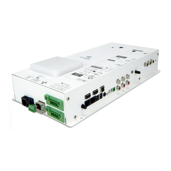
Page 5: Get Familiar With Input And Output Ports
Interface with 20V, 70V or 100V analog paging systems for paging Serial Port override. Using a USB cable, connect to a computer running FrontRow Teacher Stereo Inputs for External Audio Edition software for control and voice controlled lecture capture Connect other classroom AV equipment such as computer or DVD Control Panel Power player. -
Page 6: What Do You Want To Amplify? What Do You Want To Transmit And To What Device
3. What do you want to amplify? What do you want to transmit and to what device? Your ICR-01 Smart Receiver can amplify a variety of audio inputs, and can control devices with serial IR or network interfaces. Now is the time to plan what you want to do. -
Page 7: Step 2: Configuration
Step 2: Configuration Your ICR-01 Smart Receiver has several parameters that can be configured to tell it how to communicate with other devices in an ezRoom or Conductor installation. While each installation is different most of the default parameters will be appropriate. -
Page 8: About
Password If the project requires it you can password-protect the ICR-01 Smart Receiver configuration screens by setting a password. If setting a password for the first time, the “old password” is calypso. Choose a new one based on the school’s guidelines and record the information. -
Page 9: Load/Save
Analog Page Override For use with 25V, 70V and 100V analog paging systems. The ICR-01 Smart Receiver will mute all audio in the room when an announcement is made over the facility’s paging system. Analog page override requires a connection to the facility’s PA system. -
Page 10: System Settings
PA Release. Sets how quickly the in-room audio returns to its previous level after the announcement is complete Sensitivity. Sets how sensitive the trigger will be for muting the system. The lower the setting, the lower the sensitivity will be. While music is playing in the classroom, make a long announcement over the PA system. - Page 11 Command Channel Set the channel (A or B) for which channel the teacher mic is using as the command channel for voice commands. Equalizer Control individual aspects of the sound from your audio devices such as the bass, middle and treble frequencies. Microphone Button Mode The Teacher microphone button can be configured to trigger any defined event or to control the system with voice commands.
-
Page 12: Beacon / Lcd
5. Beacon / LCD Overview This page is where you set the color and behavior for the device’s Beacon, as well as any tone associated with a given alert state. Select a primary color, Light Off, or Do Nothing for each function. Light Off with turn the beacon off when the function is active, whereas Do Nothing will leave the beacon unchanged from its current color. - Page 13 In the event of misuse or malfunction of the equipment or any of its components or features, FrontRow Calypso LLC, its agents, employees, subsidiaries, affiliates or parent companies shall be exempt from liability for any loss, damage, injury or other consequence arising directly or indirectly therefrom.
-
Page 14: Network/Com
IT department has a DHCP server online and has set up static (fixed) IP address reservations for FrontRow devices; otherwise manually enter the IP address reserved for the device in the IP Address field. It is highly recommended that static IP addresses be used. -
Page 15: Command Line
8. Shortcuts Shortcuts Shortcuts are name substitutions. Defining Shortcuts makes deployment of multiple FrontRow devices of the same type easier. Use Shortcuts in defining actions that represent the IP addresses of the devices you’ll control. This means that your configuration file can be written as a template with IP addresses explicitly defined in only one place (the Shortcut), needing to be changed only once rather than repeatedly throughout your Actions. -
Page 16: Action Creator
9. Action Creator Actions are specific instructions that are sent to specific devices (e.g. to turn a projector on or change inputs on a projector). Once defined, you will link them to various Events which can be triggered in a variety of ways, including voice commands. To create an Action: 1. -
Page 17: Event Creator
Choose a Trigger. A trigger is a way to invoke the event you are building. Triggers can be physical devices such as a non-FrontRow push button connected to the GPI (GPI open / close), or a FrontRow device connected to the RJ45 intercom jack (Wall knob press, release, turn right, or turn left). A voice command can also be a trigger. - Page 18 Add Actions Actions can be added and will be invoked according to the mode chosen in step 4. To add actions, select them and click Add Selected. Actions can be reordered by clicking and dragging the lines to the left of the action name in the Current Action List.
-
Page 19: Step 3: Physical Installation Prep
Step 3: Physical Installation Prep Nearly everything you need to install your FrontRow Smart Receiver is included with it, or in the shipping box of the plenum or wall enclosure containing the Smart Receiver. However, you will need some basic tools and materials, depending on how your classroom is built. -
Page 20: Step 4: Plan Your Installation
• Typical maximum cable lengths are 330’ for CAT 5 network cable runs, 50’ for RS232, and 50’ for IR. Typical maximum lengths for speaker cables are 50’ though please refer to the applicable FrontRow product documentation for specific requirements. For AV plates please refer to the specific AV plate documentation. -
Page 21: Step 5: Install Your Smart Receiver
2. Connect audio cables to the auxiliary inputs. If using the CMBT Bluetooth receiver connect the Bluetooth audio out here. 3. Connect the network cable for the school LAN to the LAN port on the bottom of the Smart Receiver (the other LAN port is a pass-through connector for a FrontRow Wall Controller. - Page 22 INTERCOM port to the ICR-01 INTERCOM port. (See CMBT Installer Guide for details) 6. If the classroom will have an intercom through Conductor, connect the network cable from the FrontRow CB75 or CB85 to the INTERCOM port on the ICR-01 or to the INTERCOM MIC port on the CMBT Bluetooth audio receiver.
- Page 23 (only with CMBT) 8. If the classroom has an IR-controlled device, connect the FrontRow IR emitter cable to the IR Blaster port 9. Attach the emitter surface to the IR receiver on the IR-controlled device with the adhesive tab. The emitter surface is a shade of red, and should completely cover the device’s IR receiver and be securely in place.
- Page 24 RX, but over 10% use the reverse. 10. If you are using the CMBT Bluetooth receiver and want to control pairing via the CB6000 touch panel, connect wires from either of the ICR-01 NO relay terminals to the CMBT. (See CMBT Installer Guide for more detail)
- Page 25 To integrate your Smart Receiver to the analog paging system for paging override, use a FrontRow split core transformer and Phoenix connector (not provided with your Smart Receiver) to the PAGE OVERRIDE port.
- Page 26 12. If your classroom will be using a CB6000 or CB2000 wall controller, connect the CONTROL PANEL LAN port to a network switch that is also connected to the Smart Receiver’s LAN port OR connect the CONTROL PANEL LAN port directly to the Smart Receiver’s LAN port using a crossover network cable.
-
Page 27: Troubleshooting
Most manufacturers use pin 2 for TX and pin 3 for RX, but over 10% use the reverse. I’ve forgotten my password and need to reset the device. • Resetting your Smart Receiver involves the same procedure as that for many FrontRow devices: briefly shorting the RX and TX terminals. -
Page 28: Appendix A: Control Commands For The Smart Receiver
Appendix A: Control commands for the Smart Receiver The following commands can be used in Actions to control how a FrontRow ICR-01 Smart Receiver amplifier/switch handles audio: ICR-01 Smart Receiver / Juno Connect Master Volume Commands* Syntax: #AUDn[Mute,Volume]; Name Required/Optional... - Page 29 Network (NET) Commands* Syntax: #NET[Connection, String Type. Device ‘Command’]; Name Required/Optional Data Type Format Description Connection Required Variant Defines the connection type: • TCP/IP (1) where n is 1 or 2 • UDP (2) String Type Optional Variant Defines the string type: •...
-
Page 31: Appendix B: Configuration File Settings
Appendix B: Configuration File Settings Setting Saved in Configuration File About Custom Device Name Password Required Password Intercom / PA Audio Incoming Audio Settings Outgoing Audio Settings Push to Talk Mode Analog Page Override Settings System Settings Master Volume Microphone Volumes Aux Input Volumes OptiVoice PrioriTeach... -
Page 32: Appendix C: Network Settings
Appendix C: Network Settings This section describes how to change the setting of your computer’s wired network adapter to use a fixed (or static) IP address rather than an automatically assigned address through DHCP. The screen shots for this procedure were taken from a computer running Windows 7, and while other versions and other operating systems will look different, the general procedure is identi- cal. - Page 33 3. Click on View network status and tasks. Note that your computer may be set up differently and you may see an alternate view, such as that shown below, in which case select Network and Sharing Center.
- Page 34 4. Click on Change adapter settings. Note that your computer may display different wording such as Manage Network Connections. 5. Double click on Local Area Connection.
- Page 35 7. Select Use the following IP address. In the IP address field enter 192.168.1.100. This is the static IP address to use when connecting to FrontRow networked devices. Click into the Subnet mask field; it may automatically fill in 255.255.255.0 but if...
- Page 36 8. To return your computer to its original condition where it uses DHCP, follow the same steps described above but select Obtain an IP address automatically, press the OK button and close each popup as before.
-
Page 37: Appendix D: Connecting A Cb50 Volume Control To The Smart Receiver Intercom Port
Appendix D: Connecting a CB50 Volume Control to the Smart Receiver Intercom Port To use a CB50 rotary volume control knob with the Smart Receiver, you will need a CB-VOL kit. The CB-VOL kit includes the CB50 wired to a TB-8 (RJ45 to 8-wire adapter). Step 1 Connect the CB-VOL to the RJ45 intercom jack on the Smart Receiver using a UTP cable. - Page 38 Step 3 Define the volume and mute Events 1. On the Event Creator Page, click New to define a new Event 2. Give your Event a name 3. Choose a Trigger 4. Click Save Event 5. Repeat the steps above for each of the three actions created in Step 2 Triggers For Mute Toggle, choose Wall knob press For Increase Volume, choose Wall knob turn right...
-
Page 39: Appendix E: Connecting A Cb55 Volume/Pairing Control And Input Wall Plate To The Smart Receiver
Step 2 Connect the CMBT Bluetooth audio receiver to the Intercom jack on the ICR-01 Smart Receiver using a UTP cable. This connection provides power to the CMBT. Alternatively, you can power the CMBT from its own 15VDC power supply. - Page 40 Step 3 Define the volume and mute Actions 1. On the ICR-01 Action Creator Page (see page 13), click New to define a new action 2. Give your Action a name 3. Click the Action Entry Method dropdown and choose Master Volume Setting Wizard 4.
- Page 41 © 2018 FrontRow Calypso LLC Phonic Ear, FrontRow, Calypso and the names of Phonic Ear, Calypso, and FrontRow products are trademarks or registered trademarks of FrontRow Calypso LLC in the U.S. and other countries. Bluetooth is a registered trademark of Bluetooth SIG, Inc.
Need help?
Do you have a question about the ICR-01 and is the answer not in the manual?
Questions and answers