
Related Manuals for Oldham CTX300


Summary of Contents for Oldham CTX300
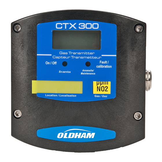
- Page 1 www.acornfiresecurity.com CTX 300 User manual Analogic Gas Detector Part Number: NP300GB Revision: N.0 → 04/2019 The Fixed Gas Detection Experts www.acornfiresecurity.com...
- Page 2 April 2019 All rights reserved. No reproduction of all or part of this document, in any form, is permitted without the written consent of Oldham Simtronics S.A.S. All information provided in this document is accurate to the best of our knowledge.
-
Page 3: Table Of Contents
www.acornfiresecurity.com Contents Chapter 1 | General Information ..........5 User Manual ....................5 Symbols used ..................... 5 Safety instructions ..................6 Important information ................. 6 Liability limits ....................7 Chapter 2 | Introduction ............9 General Information ................... 9 Composition ..................... 10 Chapter 3 | Installation and connection ........ - Page 4 www.acornfiresecurity.com Chapter 9 | Annex ..............45 Indications for calibrating the CTX 300 SC ..........45 CTX 300 overview ..................46 CTX 300 User manual www.acornfiresecurity.com...
-
Page 5: Chapter 1 | General Information
The aim of this manual is to supply simple and accurate information to the user. Oldham Simtronics cannot be held liable for any misinterpretations in the reading of this manual. In spite of our efforts to produce an error-free manual, it may nonetheless contain some unintentional technical inaccuracies. -
Page 6: Safety Instructions
www.acornfiresecurity.com This symbol indicates: You must refer to the instructions. This symbol indicates: Warning! In the present mode of use, failure to adhere to the instructions preceded by this symbol can result in a risk of electric shock and/or death. European Union (and EEA) only. -
Page 7: Liability Limits
43 control unit, injuries, loss of time, financial or material loss, or any direct or indirect consequence of loss occurring in the context of the use or impossibility of use of the product, even in the event that Oldham Simtronics has been informed of such damage. 1 – General information... - Page 8 www.acornfiresecurity.com CTX 300 User manual www.acornfiresecurity.com...
-
Page 9: Chapter 2 | Introduction
Chapter 2 | Introduction General Information CTX300 gas detectors are designed to measure toxic gases, CO or vapors and oxygen. With robust materials, a specifically-adapted design, appropriate accessories, stainless bolts and a polyamide case (IP54), CTX 300 detectors are designed to withstand the roughest conditions. -
Page 10: Composition
www.acornfiresecurity.com Composition Sensor type CTX 300 Toxic Oxygen Semi- conductor Gases detected Common toxic Oxygen. - Combustible gases detected. gas. - Solvents. - Some Freons. Detection Electrochemical Electrochemical Infrared Semiconductor method sensors (1). sensor. absorption. sensor. Type of sensor Pre-calibrated Pre-calibrated Pre-calibrated Removable... -
Page 11: Chapter 3 | Installation And Connection
www.acornfiresecurity.com Chapter 3 | Installation and connection Installing the detectors Layout While the measuring sensor is always located on the underside of the detector, several factors determine where the detector should be located: ■ If the gas being measured is lighter than the air, place the detector near the ceiling. ■... - Page 12 www.acornfiresecurity.com Mechanical installation Figure 2: overall dimensions of the CTX 300. Figure 3: drilling diagram for wall mounting (view of the side flatten onto the ceiling). CTX 300 User manual www.acornfiresecurity.com...
-
Page 13: Electrical Connections
Screw CHC LI2 6902218 Stainless Electrical connections Wiring specifications If needed, consult the grounding instructions for Oldham Simtronics instruments and related connection materials in Annex 1. Connections for the various types of sensors Wire CTX 300 (TOX/OX) CTX 300 (TOX/OX) - Page 14 Terminal number (+) V DC power supply: Output signal: Both wires are the 4-20 mA 2-wire loop. +24 VDC Control unit Detector Signal Figure 6: connection of a 2-wire sensor to an Oldham Simtronics control unit. CTX 300 User manual www.acornfiresecurity.com...
- Page 15 Other control unit +24 VDC Detector Signal Figure 7: Connection of a 3-wire CTX300 sensor to a non-Oldham Simtronics control unit. Maximal load = 200 Ω. Power supply 15 ≤ Vcc ≤ 32. 18 ≤ Vcc ≤ 30 for CO sensor.
- Page 16 Operating mode CTX300 with display ■ Remove the 4 screws (ref. 1). ■ Remove the cover (ref. 2). Figure 9 ■ Completely remove the screw (ref. 4). ■ Unscrew the screw a few turns (ref. 3). Figure 10 ■...
- Page 17 www.acornfiresecurity.com CTX 300 without display ■ Unscrew the 4 screws (ref. 1). ■ Remove the cover (rep. 2). ■ Proceed to wire the sensor according to the terminal location. Figure 12 3 - Installation and connection www.acornfiresecurity.com...
- Page 18 www.acornfiresecurity.com CTX 300 User manual www.acornfiresecurity.com...
-
Page 19: Chapter 4 | Powering Up And Use
www.acornfiresecurity.com Chapter 4 | Powering up and use Powering up ■ The sensor turns on when connected to a power supply. ■ If the sensor has a display, the green LED will be lit (ref. 2) and a value will appear on the display screen (ref. -
Page 20: 4-20 Ma Analog Output
www.acornfiresecurity.com 4-20 mA analog output For CTX 300 sensors, the 4-20 mA output current is proportional to the gas level. The various states of the 4-20 mA output are: 1 mA to indicate a fault. ■ ■ Between 4 and 20 mA for measurement values. ≥... -
Page 21: Chapter 5 | Maintenance
The frequency of calibrations shall be appropriate according to the results of the tests (humidity, temperature, dust, etc.); however, it must not exceed one year. The general manager should put safety procedures in place on-site. OLDHAM SIMTRONICS cannot be held responsible for their enforcement. Calibration... - Page 22 30% of the measurement range at a minimum). The recommended rate is 60 l/h. Note: when dealing with dangerous gases, you MUST consult a specialized Oldham Simtronics technician or use another sensor pack recently pre-calibrated at a factory.
- Page 23 www.acornfiresecurity.com ■ Wait for the measurement to stabilize (displayed on screen) and adjust the zero using ZERO potentiometer located on the sensor pack (ref. 2). ■ Inject the recommended calibration gas at a flow rate of 30 l/h. ■ Wait for the measurement to stabilize. ■...
- Page 24 www.acornfiresecurity.com case: CTX 300 without display (except for O et SC) ■ The sensor is operating. ■ Verify that the sensor is located in a clean-air environment. calibration follow recommendations. ■ Connect a voltmeter to the AF+ and AF- terminals (caliber mV/DC). Figure 18 ■...
- Page 25 www.acornfiresecurity.com ■ Adjust the displayed value using the potentiometer (Figure 19, rep.1). Example CO sensor. Scale 0-300 ppm. Standard gas concentration: 100 ppm. Reading: 533 mV. ■ Shut off the calibration gas injection. ■ Withdraw the gas injection pipe. ■ Then wait and check that the scale has returned to zero.
- Page 26 - 0 mV for 0% O Figure 21 Note: signal sent from the CTX300 (toxic or oxygen) sensor to the control unit can be measured on the main circuit by connecting a millivoltmeter to the pins designed for this purpose (Figure 22).
- Page 27 www.acornfiresecurity.com CTX 300 calibration (for Semiconductor) This is a Semiconductor type sensor. ■ Flip the switch (rep. 1) into the CAL position. Figure 23 ■ Ensure that the sensor is in clean air, otherwise inject synthetic air into it using the calibration kit and referring to the recommendations below.
- Page 28 www.acornfiresecurity.com ■ Connect a voltmeter as indicated and adjust, using potentiometer p5 (ref. 1). The output signal must be equal to 880 mV. ■ Next, inject the calibration gas at a flow rate of 30 l/h (refer to paragraph Indications for calibrating the CTX 300 SC, on page 45).
-
Page 29: Replacing A Sensor
www.acornfiresecurity.com Replacing a sensor Sensors must be replaced: ■ When calibration is no longer possible (no sensitivity); ■ During preventative maintenance. The replacement sensor should be identical to the original sensor (same gas, same range). After a sensor has been replaced, a calibration or test (for pre-calibrated sensors) must be conducted. - Page 30 www.acornfiresecurity.com CTX 300 User manual www.acornfiresecurity.com...
-
Page 31: Chapter 6 | Spare Parts
Chapter 6 | Spare parts List of spare parts for different detectors. Replacement parts must imperatively be guaranteed origin Oldham Simtronics. Otherwise, material safety could be jeopardized. CTX/COX 300 toxic or oxygen sensors Description Picture 6147868 CTX 300 tool kit. - Page 32 www.acornfiresecurity.com Description Picture 6327906 Device for remote gas introduction. 6335953 Replacement filter. PTFE protector filter. Pre-calibrated oxygen sensor pack 6313C2A CTX 300 O , 0-30 % vol sensor pack. (2years) 6313C5A CTX 300 O , 0-30 % vol sensor pack. (5years) 6313660 CTX 300 O...
- Page 33 www.acornfiresecurity.com Description Picture 6313640 CTX 300 NO - 30 ppm sensor pack. 6314001 CTX 300 NO - 100 ppm sensor pack. 6313645 CTX 300 ETO - 30 ppm sensor pack. 6313646 CTX 300 SO - 10 ppm sensor pack. 6313647 CTX 300 SO - 30 ppm sensor pack.
- Page 34 www.acornfiresecurity.com Description Picture 6815919 CTX 300 without display label. 6815921 CTX 300 wit display label. 6451466 Display card. 6815923 Localization sticker. 6451644 Motherboard. CTX 300 User manual www.acornfiresecurity.com...
-
Page 35: Csc 300 Semiconductor Sensors
www.acornfiresecurity.com CSC 300 semiconductor sensors Description Picture 6147868 CTX 300 tool kit. 6322420 Mounting brace and bolts (CTX 300 ceiling mount). 6323607 Gas collector (stainless). 6335919 Calibration kit (humidifier filter + pipe). 6335918 Humidifier filter. Replacement sensors 6313544 Sensor for R134A, R11, R23, R143A, R404A, R507, R410A, R32, R407C, R408A. - Page 36 www.acornfiresecurity.com CTX 300 User manual www.acornfiresecurity.com...
-
Page 37: Chapter 7 | Certification
www.acornfiresecurity.com Chapter 7 | Certification The following page reproduces the EC declaration of conformity. 7 - Certification www.acornfiresecurity.com... - Page 38 www.acornfiresecurity.com CTX 300 User manual www.acornfiresecurity.com...
- Page 39 www.acornfiresecurity.com 7 - Certification www.acornfiresecurity.com...
- Page 40 www.acornfiresecurity.com CTX 300 User manual www.acornfiresecurity.com...
-
Page 41: Chapter 8 Technical Specifications
(outer diameter 6 to 11 mm) 15 to 32 V DC Power supply CTX 300 (Tox and O ) without display unit: 27 mA CTX300 CO2 without display: 60mA Power consumption CTX 300 with display unit: 110 mA CTX 300 semiconductor versions: 100mA -20°C to + 50°C, -4°F to + 122°F with display (sensor... - Page 42 www.acornfiresecurity.com 30.0% -20°C to +50°C 10% to 95% RH +/-1.5% 30.0% -40°C to +50°C 10% à 95% RH +/-1.5% 100% +5°C to +40°C 10% to 95% RH +/-1.5% <20 -20°C to +50°C 10% to 95% RH +/-1.5% -20°C to +50°C 10% to 95% RH +/-1.5% 1000...
- Page 43 www.acornfiresecurity.com 3.00 -20°C to +50°C 10% to 95% RH +/-2% COCl 3.00 -20°C to +40°C 10% to 95% RH +/-1.5% Methylene -20°C to +55°C 10% to 95% RH chloride Methyl chloride -20°C to +60°C 10% to 95% RH -20°C to +50°C 10% to 95% RH Toluene 2000...
- Page 44 www.acornfiresecurity.com CTX 300 User manual www.acornfiresecurity.com...
- Page 45 www.acornfiresecurity.com Chapter 9 | Annex Indications for calibrating the CTX 300 SC This information relates to the CTX 300 semiconductor. Measurement After sale service Gas types Test gas range standard gas Methyl Chloride 2000 ppm H = 190 6313545 500 ppm 50 ppm CH ppm ±...
- Page 46 www.acornfiresecurity.com CTX 300 overview Figure 27: CTX 300 with sensor pack and display – overview. CTX 300 User manual www.acornfiresecurity.com...
- Page 47 www.acornfiresecurity.com Figure 28: CTX 300 – overview. 9 – Annex www.acornfiresecurity.com...
- Page 48 www.acornfiresecurity.com Figure 29: CTX 300 semiconductor– overview. CTX 300 User manual www.acornfiresecurity.com...
Need help?
Do you have a question about the CTX300 and is the answer not in the manual?
Questions and answers