
Subscribe to Our Youtube Channel
Related Manuals for Oldham ctx 300


Summary of Contents for Oldham ctx 300
- Page 1 CTX 300 User manual Analogic Gas Detector Part Number: NP300GB Revision: K.1 The Fixed Gas Detection Experts...
- Page 2 April 2015 All rights reserved. No reproduction of all or part of this document, in any form, is permitted without the written consent of Oldham S.A.S. All information provided in this document is accurate to the best of our knowledge.
-
Page 3: Table Of Contents
Replacing a sensor .................. 35 Disposal ....................35 Chapter 6 | Spare parts ............37 CTX/COX 300 toxic or oxygen sensors ........... 37 CSC 300 semiconductor sensors............. 40 CTX 300 – CO sensors ................41 Chapter 7 | Certification ............43 Contents... - Page 4 Chapter 8 Technical specifications ........47 Chapter 9 | Annex ..............51 Wiring specification .................. 51 Indications for calibrating the CTX 300 SC ..........53 CTX 300 overview ..................54 CTX 300 User manual...
-
Page 5: Chapter 1 | General Information
The aim of this manual is to supply simple and accurate information to the user. Oldham cannot be held liable for any misinterpretations in the reading of this manual. In spite of our efforts to produce an error-free manual, it may nonetheless contain some unintentional technical inaccuracies. -
Page 6: Safety Instructions
The modification of the material and the use of parts of an unspecified origin shall entail the cancellation of any form of warranty. The use of the unit has been projected for the applications specified in the technical characteristics. Exceeding the indicated values cannot in any case be authorized. CTX 300 User manual... -
Page 7: Liability Limits
Liability limits Neither Oldham nor any other associated company under any circumstances can be held liable for any damage, including, without limitations, damages for loss or interruption of manufacture, loss of information, defect of the MX 43 control unit, injuries, loss of time, financial or material loss, or any direct or indirect consequence of loss occurring in the context of the use or impossibility of use of the product, even in the event that Oldham has been informed of such damage. - Page 8 CTX 300 User manual...
-
Page 9: Chapter 2 | Introduction
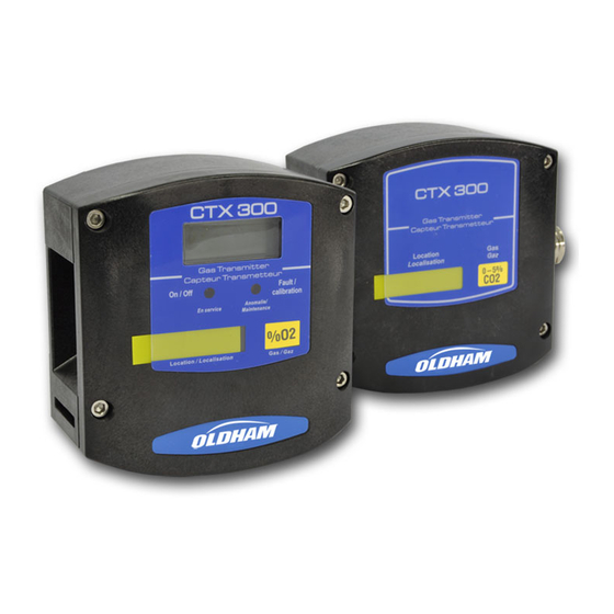
With robust materials, a specifically-adapted design, appropriate accessories, stainless bolts and a polyamide case (IP54), CTX 300 detectors are designed to withstand the roughest conditions. Figure 1: overview of a CTX 300 with display (left) and without display (right). 2 - Introduction... -
Page 10: Composition
Composition Sensor type CTX 300 Toxic Oxygen Semi- conductor Gases Common toxic Oxygen. - Combustible detected gases detected. gas. - Solvents. - Some Freons. Detection Electrochemical Electrochemical Semiconductor Infrared method sensors (1). sensor. sensor. absorption. Type of sensor Pre-calibrated Pre-calibrated... -
Page 11: Chapter 3 | Installation And Connection
Chapter 3 | Installation and connection Installing the detectors Layout While the measuring sensor is always located on the underside of the detector, several factors determine where the detector should be located: ■ If the gas being measured is lighter than the air, place the detector near the ceiling. ■... - Page 12 Mechanical installation Figure 2: overall dimensions of the CTX 300. Figure 3: drilling diagram for wall mounting (view of the side flatten onto the ceiling). CTX 300 User manual...
-
Page 13: Electrical Connections
Stainless Screw CHC LI2 6902218 Stainless Electrical connections Wiring specifications If needed, consult the grounding instructions for Oldham instruments and related connection materials in Annex 1. Connections for the various types of sensors Wire CTX 300 (TOX/OX) CTX 300 (TOX/OX) - Page 14 Output signal: +24 VDC Control unit Detector Signal Figure 5: connection of a 3-wire sensor to an Oldham control unit. Connection of a 2-wire sensor to an Oldham control unit Wire Terminal number (+) V DC power supply: Output signal: Both wires are the 4-20 mA 2-wire loop.
- Page 15 Power supply 15 ≤ Vcc ≤ 32. 18 ≤ Vcc ≤ 30 for CO sensor. I max = 130 mA. Connection of a 2-wire 4-20mA sensor to a non-Oldham control unit and to an internal power supply Other control unit...
- Page 16 ■ Connect the cable (ref. 6) to the connector. Refer paragraph Connections for the various types of sensors on page 13. ■ Return the display circuit to its original position and replace the cover. Figure 11 CTX 300 User manual...
- Page 17 CTX 300 without display ■ Unscrew the 4 screws (ref. 1). ■ Remove the cover (rep. 2). ■ Proceed to wire the sensor according to the terminal location. Figure 12 3 - Installation and connection...
- Page 18 CTX 300 User manual...
-
Page 19: Chapter 4 | Powering Up And Use
In case of a problem, verify that the maintenance switch (ref. 1), located on the main circuit, is in the MES (measure) position. Figure 14: CTX 300 circuit board. Figure 15: CTX 300 SC main circuit board. 4 – Powering up... -
Page 20: Ma Analog Output
Figure 16: CTX 300 CO main circuit board. This card does is not equipped with a MES-CAL switch. 4-20 mA analog output For CTX 300 sensors, except for the CO sensor, the 4-20 mA output current is proportional to the gas level. Notes: ■... -
Page 21: Chapter 5 | Maintenance
The adjustment operations in this paragraph are reserved for authorized, trained personnel because they may compromise detection reliability Gas detectors are safety devices. OLDHAM recommends the regular testing of fixed gas detection installations. This type of test consists of injecting the calibration gas into the detector at a sufficient concentration to activate the pre-set alarms. - Page 22 30% of the measurement range at a minimum). The recommended rate is 60 l/h. Note: when dealing with dangerous gases, you MUST consult a specialized Oldham technician or use another sensor pack recently pre-calibrated at a factory.
- Page 23 ■ Flip the maintenance switch (ref. 1) into the CAL (calibration) position: the yellow light (Figure 18, ref. 2) will be lit and the sensor will send a 2 mA current control unit (Maintenance mode). ■ Verify that the sensor is located in a clean-air environment.
- Page 24 CTX 300 without display (except for O , SC and C0 ■ The sensor is operating. ■ Flip the maintenance switch (ref. 1) into the CAL (calibration) position: the sensor will send a 2 mA current to the control unit (Maintenance mode).
- Page 25 ■ Adjust the displayed value using the potentiometer (Figure 24, rep.1). Example CO sensor. Scale 0-300 ppm. Standard gas concentration: 100 ppm. Reading: 533 mV. ■ Shut off the calibration gas injection. ■ Withdraw the gas injection pipe. ■ Then wait and check that the scale has returned to zero.
- Page 26 22. Proceed only with adjusting sensitivity (rep. 1) by injection of test gas. Figure 26 case: CTX 300 O2 without display screen nor LED ■ See paragraph 2 case: CTX 300 without display on page 24. Proceed only with adjusting sensitivity (rep.
- Page 27 CTX 300 calibration (for Semiconductor) This is a Semiconductor type sensor. ■ Flip the switch (rep. 1) into the CAL position. Figure 29 ■ Ensure that the sensor is in clean air, otherwise inject synthetic air into it using the calibration kit and referring to the recommendations below.
- Page 28 Stop injecting the calibration gas. ■ Verify that the reading returns to zero (880 mV). If it does not, repeat the entire procedure. ■ Calibration is complete. ■ Flip the switch (ref. 1) into the MES (Measure) position. Figure 32 CTX 300 User manual...
- Page 29 CTX 300 CO calibration This is a Carbone dioxide type sensor. ■ Warning: the sensor should be turned on for 15 minutes before adjustments are made. The following text describes the steps necessary to adjust the transmitter (first calibration). ■...
- Page 30 CTX 300 CO linearization card ■ If you use a linearization card, the connection is the following. Terminal A Central terminal number 2 (GND) 3 (+24V) 1 (I out) Terminal B Central terminal number Iout +24V +24V Figure 34 Calibration curves...
- Page 31 Display Current Display Current ppm CO ppm CO % range % range 5500 16.16 6.24 6000 16.64 1000 8.32 6500 17.12 1500 7000 17.6 2000 10.88 7500 18.08 2500 11.84 8000 18.4 3000 12.8 8500 18.88 3500 13.6 9000 19.36 4000 14.24 9500...
- Page 32 48.4 11.74 1,50 60.1 13.62 2,00 68.6 14.98 2,50 75.6 16.1 3,00 82.4 17.18 3,50 86.7 17.87 4,00 91.7 18.67 4,50 95.8 19.33 5,00 -IR transmitter output signal – 0-5 % scale. Figure 36: signal CO CTX 300 User manual...
- Page 33 Concentration % CO Display Current % CO % range 0,00 1,00 41.25 10,6 2,00 56.875 13,1 3,00 67.5 14,8 4,00 75.625 16,1 5,00 80.625 16,9 6,00 86.875 17,9 7,00 91.25 18,6 8,00 95.625 19,3 9,00 98.75 19,8 10,00 20,0 -IR transmitter output signal – 0-10 % scale. Figure 37 : signal CO 5 –...
- Page 34 74.2 15.87 13.4 6.14 80.4 16.86 21.6 7.46 85.6 17.7 28.4 8.54 90.7 18.51 38.1 10.1 93.8 19.01 54.6 12.74 96.9 19.5 14.87 -IR transmitter output signal – 0-50 % scale. Figure 38 : signal CO CTX 300 User manual...
-
Page 35: Replacing A Sensor
The user therefore has an obligation to separate the CTX 300 sensor from other waste to ensure that it is recycled safely for the environment. For further details on existing collection sites, contact the local administration or seller of the product. - Page 36 CTX 300 User manual...
-
Page 37: Chapter 6 | Spare Parts
Chapter 6 | Spare parts List of spare parts for different detectors. Replacement parts must imperatively be guaranteed origin Oldham. Otherwise, material safety could be jeopardized. CTX/COX 300 toxic or oxygen sensors Description Picture 6147868 CTX 300 tool kit. 6322420 Mounting brace and bolts (CTX 300) ceiling mount. - Page 38 CTX 300 O , 0-100 % vol sensor pack. Pre-calibrated toxic sensor pack 6313627 CTX 300 CO - 100 ppm sensor pack. 6313628 CTX 300 CO - 300 ppm sensor pack. 6313629 CTX 300 CO - 1000 ppm sensor pack.
- Page 39 - 30 ppm sensor pack. 6313651 CTX 300 H - 100 ppm sensor pack. 6313652 CTX 300 HCL - 30 ppm sensor pack. 6313653 CTX 300 HCL - 100 ppm sensor pack. 6313654 CTX 300 HCN - 10 ppm sensor pack.
-
Page 40: Csc 300 Semiconductor Sensors
CSC 300 semiconductor sensors Description Picture 6147868 CTX 300 tool kit. 6322420 Mounting brace and bolts (CTX 300 ceiling mount). 6323607 Gas collector (stainless). 6335919 Calibration kit (humidifier filter + pipe). 6335918 Humidifier filter. Replacement sensors 6313544 Sensor for R134A, R11, R23, R143A, R404A, R507, R410A, R32, R407C, R408A. - Page 41 CTX 300 – CO sensors Description Picture 6147868 CTX 300 tool kit. 6451618 Motherboard. 6351233 Linearization card. 6799188 Gas introduction device. Replacement sensors 6451612 - 0 - 1 % sensor. 6451611 - 0-5 % or 0-10 % sensor. 6451610 - 0 - 50 % sensor.
- Page 42 CTX 300 User manual...
-
Page 43: Chapter 7 | Certification
Chapter 7 | Certification The following page reproduces the EC declaration of conformity. 7 - Certification... - Page 44 CTX 300 User manual...
- Page 45 7 - Certification...
- Page 46 CTX 300 User manual...
-
Page 47: Chapter 8 Technical Specifications
CCSA – Class 4812 10 – Signal Appliances-Detectors CSAUS – Class 4812 86 - Signal Appliances-Miscellaneous Type 1 according to EN 50270:06 32 ohms max loop for CTX 300 with display unit and for solid states and CO sensor versions... - Page 48 -20°C to +40°C 10% to 95% RH +/-3% <20 30.0 -20°C to +50°C 10% to 95% RH +/-3% 10.0 -10°C to +30°C 10% to 95% RH +/-3% 1.00 -20°C to +50°C 10% to 95% RH +/-3% CTX 300 User manual...
- Page 49 1.00 -20°C to +50°C 10% to 95% RH +/-3% 1.00 -20°C to +50°C 10% to 95% RH +/-3% 3.00 -20°C to +50°C 10% to 95% RH +/-2% COCl 3.00 -20°C to +40°C 10% to 95% RH +/-1.5% Methylene -20°C to +55°C 10% to 95% RH chloride Methyl chloride...
- Page 50 CTX 300 User manual...
-
Page 51: Chapter 9 | Annex
Wiring specification Subject This specification defines the general principles that apply to the design and manufacture of grounding devices for Oldham instrumentation. Reference documents The electrical installation shall comply with French regulations in force, with all European directives, all AFNOR standards and codes in force, insofar as they apply, as well as the client’s general and particular specifications. - Page 52 Non-ATEX zone: LYCY. The cables listed below were not included in the electromagnetic compatibility tests for our products. Use at your own risk. ■ U1000 R2V(FV). ■ U1000 RGPFV-RH. ■ A/H07 RN-F. ■ FRN07 RN-F. ■ GVS-RH. CTX 300 User manual...
-
Page 53: Indications For Calibrating The Ctx 300 Sc
Indications for calibrating the CTX 300 SC This information relates to the CTX 300 semiconductor. Gas types Measurement After sale service Test gas range standard gas 6313545 Methane 100% LEL 20 % LEL 1 % CH Hydrogen 100% LEL 20 % LEL 0.8 % H... -
Page 54: Ctx 300 Overview
CTX 300 overview Figure 39: CTX 300 with sensor pack and display – overview. CTX 300 User manual... - Page 55 Figure 40: CTX 300 – overview. 9 – Annex...
- Page 56 Figure 41: CTX 300 semiconductor– overview. CTX 300 User manual...
- Page 57 Figure 42: CTX 300 infrared – 1% volume CO – overview. 9 – Annex...
- Page 58 Figure 43: CTX 300 infrared – 5% volume CO – overview. CTX 300 User manual...
- Page 59 Figure 44: CTX 300 infrared – 10% volume CO – overview. 9 – Annex...
- Page 60 Figure 45: CTX 300 infrared – 50% volume CO – overview. CTX 300 User manual...
- Page 64 The Fixed Gas Detection Experts EUROPEAN PLANT AND OFFICES Z.I. Est – rue Orfila CS 20417 – 62027 Arras Cedex FRANCE Tél: +33 (0)3 21 60 80 80 – Fax: +33 (0)3 21 60 80 00 Website: http://www. .com oldhamgas AMERICAS ASIA PACIFIC EUROPE...
Need help?
Do you have a question about the ctx 300 and is the answer not in the manual?
Questions and answers