Sign In
Upload
Download
Table of Contents
Contents
Add to my manuals
Delete from my manuals
Share
URL of this page:
HTML Link:
Bookmark this page
Add
Manual will be automatically added to "My Manuals"
Print this page
×
Bookmark added
×
Added to my manuals
Manuals
Brands
Oldham Manuals
Gas Detectors
CPS Series
User manual
Oldham CPS Series User Manual
Hide thumbs
1
2
3
4
5
Table Of Contents
6
7
8
9
10
11
12
13
14
15
16
17
18
19
20
21
22
23
24
25
26
27
28
29
30
31
32
33
34
35
36
37
38
39
40
41
42
43
44
45
46
47
48
49
50
51
52
53
54
55
56
57
58
59
60
61
62
63
64
65
66
67
68
69
70
71
72
73
74
75
76
page
of
76
Go
/
76
Contents
Table of Contents
Bookmarks
Table of Contents
Table of Contents
Chapter 1 Overview of the CPS System
The CPS Central Controller
Digital Addressable Modules
Digital Linking
The COM_CPS Software Application
System Architecture
Chapter 2 Assembly / Installation
Installation of the CPS Central Controller
Mounting the Metal Wall Casing
Mounting the 19" 4U Rack
Installing Digital Modules
Mounting the CPS 10 Sensor Module
Mounting the Other Modules
Connection of Modules in a Line
Chapter 3 The CPS Central Measuring Controller
View of Rack-Mounted CPS
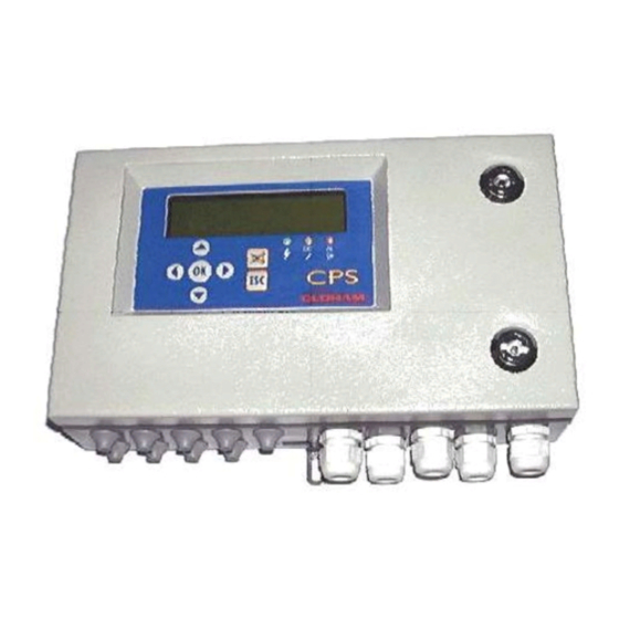
View of Wall-Mounted CPS
Central Controller Electrical Connections
Main Power Supply
Grounding the Central Controller
Digital Lines
Internal Relay Dry Contacts
RS-485 Serial Link out
Overview of the Motherboard
Inspecting the Digital Buses
Mini-Switches
Internal Relay and Buzzer
USB / RS-232 Serial Connectors
RS-485 Serial Connection (3)
Printer (Optional Feature)
The Front Panel Circuit
Display Screen
Keys
Lights
Alarm Thresholds
Alarm Acknowledgement
Chapter 4 Digital Modules
View of Digital Modules
Connecting Digital Modules
General Topology of the RS-485 Network
Wiring the Digital Network
Configuring the Communication Settings
Slave Address
End of Line Resistor
CPS 10 Detector Module
Available Detector Types
Detector Settings
External Relay Module
Relay Status Lights
Positive/Negative" Relay Security
Relay Configuration
Analog Outputs Module
Logic Input Module
Chapter 5 Detailed Menus
Menu Tree
Start-Up Phase
Control Menu
Normal Display
Sensor Display
Events
Relay Status
4-20 Ma Output Status
Printing
Acces Code
System Menu
Line, Module, Relay Action
Date and Time
Start-Up Configuration
Maintenance Menu
Simulation
Module Verification
Bus Faults
Reset Maintenance
Chapter 6 Maintenance
Program Transfer
PC CPS Transfer
CPS PC Transfer
Error Messages
Checksum Error
Testing and Calibration of Stable Installations
Sensor Replacement
Semi-Automatic Calibration
Manual Calibration
Semi-Automatic Calibration Device
Central Controller Maintenance
Lithium Battery
Back-Up Battery Pack
Scrapping of CPS System
Chapter 7 Technical Specifications
CPS Central Controller
CPS 10 Sensor Module
CPS RM4 or RM8 Relay Module
CPS DI16 Logic Inputs Module
CPS AO4 Analog Output Module
Chapter 8 Annexes
Chapter 9 UE Declaration of Conformity
Advertisement
Quick Links
1
The Cps Central Controller
Download this manual
CPS_CPS 10
User manual
System
Part Number: NPCPSGB
Revision: J.2
The Fixed Gas Detection Experts
Table of
Contents
Previous
Page
Next
Page
1
2
3
4
5
Advertisement
Table of Contents
Need help?
Do you have a question about the CPS Series and is the answer not in the manual?
Ask a question
Questions and answers
Related Manuals for Oldham CPS Series
Gas Detectors Oldham CTX300 User Manual
Analogic gas detector (48 pages)
Gas Detectors Oldham CPS10 System User Manual
(76 pages)
Gas Detectors Oldham OLCT 10N User Manual
Digital gas detector (44 pages)
Gas Detectors Oldham OLCT 20 User Manual
(36 pages)
Gas Detectors Oldham Surveyor 4B Installation, Operating And Maintenance Manual
(20 pages)
Gas Detectors Oldham OLC100 User Manual
Explosimeter, toxic gas and oxygen detector (63 pages)
Gas Detectors Oldham OLC 100 User Manual
(76 pages)
Gas Detectors Oldham SV 4B User Manual
Gas surveyor (24 pages)
Gas Detectors Oldham MX62 Installation And Utilisation Manual
Gas detection system (84 pages)
Gas Detectors Oldham OLC 10 User Manual
Analog gas detector (26 pages)
Gas Detectors Oldham OLC 10 User Manual
Analog gas detector, non atex version (28 pages)
Gas Detectors Oldham MX 62 User Manual
Gas detection system (74 pages)
Gas Detectors Oldham OLC 100 User Manual
(72 pages)
Gas Detectors Oldham CTX 300 CO2 User Manual
Analogic co2 gas detector (36 pages)
This manual is also suitable for:
Cps10 system
Table of Contents
Print
Rename the bookmark
Delete bookmark?
Delete from my manuals?
Login
Sign In
OR
Sign in with Facebook
Sign in with Google
Upload manual
Upload from disk
Upload from URL


Need help?
Do you have a question about the CPS Series and is the answer not in the manual?
Questions and answers