
Related Manuals for Oldham MX 62


Summary of Contents for Oldham MX 62
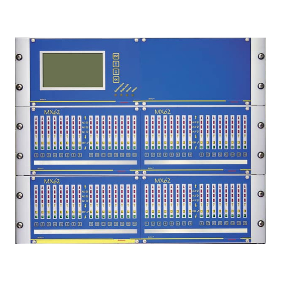
- Page 1 MX 62 User Manual Gas Detection System Part Number: NPM62GB Version: G.0 The Fixed Gas Detection Experts...
- Page 2 Subject to change without notice FE BA WinPro MX 62 R6 GB 1604CBR...
- Page 3 Wherever combustible gases, toxic gases and oxygen are to be monitored, OLDHAM is a relia- ble partner for the matters of safety engineering. This operation manual describes the functionality and mainte- nance of as well as the scope of possible connections to the gas ®...
- Page 4 Page 4...
- Page 5 It is important that you read this entire manual carefully and thoroughly. OLDHAM shall not be held responsible for any damage to the equipment or for any physical injury or death resulting in whole or in part from the inappropriate use, installation, or storage of the equipment, which is the result of not complying with the instructions and warnings, and/or with the standards and regulations in force.
- Page 6 Destruction of the equipment European Union (and EEA) only. This symbol indicates that, in conformity with directive DEEE (2002/96/CE) and according to local regulations, this product may not be discarded together with household waste. It must be disposed of in a collection area that is set aside for this purpose, for example at a site that is officially designated for the recycling of electrical and electronic equipment (EEE) or a point of exchange for authorized products in the event of the acquisition of a new product of the same type as before.
-
Page 7: Table Of Contents
contents PRESENTATION ..................... 11 SYSTEM CONFIGURATION ................11 2.1. Description of Modules ..........................12 2.1.1. Controller module (CM) ......................12 2.1.2. Analog input module (AEM)......................12 2.1.3. LED Module ..........................13 2.1.4. Basic relay (RBM) and Extension relay module (REM) ............13 2.1.5. - Page 8 OPERATION OF LCD MODULE ..............37 4.1. Display of channels ..........................37 4.2. Menu ................................. 37 4.2.1. System / LED-test.......................... 38 4.2.2. System / System status ........................38 4.2.3. System / System information......................38 4.2.4. Channel information / Actual information ................. 38 4.2.5.
- Page 9 CUT-OUT FOR CONTROL PANEL INSTALLATION ........57 10. ACCESSORIES AND SPARE PARTS ............59 11. CERTIFICATIONS ................... 61 11.1. CE accreditation ..........................61 11.2. Performance approvals ........................61 11.3. Special conditions for safe use ......................62 12. EU DECLARATION OF CONFORMITY ............65 13.
- Page 10 Page 10...
-
Page 11: Presentation
Presentation ® WinPro / MX62 is a stationary control system to be used in combination with a variety of detectors for continuous detection of combustible gases, toxic gases and oxygen. Main features are a high reliability and flexibility. The flexibility refers to all areas, as there are free programmability, installation of relay and analog output modules and the optional installation in wall-mounted housings, 19 inch racks or control panels. -
Page 12: Description Of Modules
Profibus module (PBM) Analog input extension module (AEAM) LCD copy module MIMIC module Each RBM provides eight relays to be freely allocated. The REM allows the addition of eight relays with a minimum of space. The AAM provides either 4-20 mA or 0-10 V outputs. The AEAM can be used in combination with the AEM to connect smoke ... -
Page 13: Led Module
2.1.3. LED Module The status of each channel is indicated by LEDs. Each detector can be connected to any channel. Operation of the buttons for the respective channels displays additional information about the connected detector on the LCD module and triggers further channel functions such as alarm suspension, operational test, channel disconnection and calibration mode. -
Page 14: Loop Module (Loopm)
ATTENTION! It is not allowed to use the ADVANCED relay functions in a safety related ATEX application with measuring function for explosion protection or a SIL application. Up to eight relay modules with a total of 128 relays can be integrated into the system. -
Page 15: Analog Output Module (Aam)
2.1.6. Analog output module (AAM) The employment of up to eight AAMs with a total of 64 outputs allows transmission of detector signals (4-20 mA or 0-10 V). An address between 1 and 8 is allocated to each module by rotary switch. ATTENTION! Though the AAM has two microcontrollers, only one controller is able to transmit data to the outputs. -
Page 16: Analog Input Extension Module (Aeam)
2.1.9. Analog input extension module (AEAM) The AEAM is intended for the connection of smoke detectors. It is possible to connect up to 8 smoke detectors at each AEAM. The AEAM is an extension module and has to be plugged on the AEM. ATTENTION! It is not allowed to connect gas detectors to the AEAM. -
Page 17: Redundancy Of Winpro / Mx62
Each MIMIC module copies exactly one LED module. It is possible to connect a further LED module to the MIMIC module or to copy the primary LED module by using the open collector outputs of the MIMIC modules. The MIMIC Module just shows status information of the channels. The buttons of the LED Module are deactivated. - Page 18 Page 18...
-
Page 19: Operation Of The System Winpro / Mx62
Operation of the System WinPro / MX62 ® During normal operation, the WinPro / MX62 continuously processes signals of the connected detectors. ® Besides, WinPro / MX62 can enter into other modes for servicing or in case of malfunction. This chapter describes the various operating modes and the respective system performance. -
Page 20: Isa Procedure (Slow Flashing Channel Led)
These blinking LEDs indicate a certain system status. For detailed description, please see: System failure (see chapter 3.6) Single mode (see chapter 3.5) Service mode (see chapter 3.4) On the CM a separate relay output is allocated to each of these three modes. The blinking LED Battery signals power failure, which provides an emergency power supply (optional). -
Page 21: Sytem Start-Up
minimum one channel is still deactivated, this relay will operate and the user is informed that not all channels are activated. The alarm suppression and deactivation of a channel have effect on the activation of the general buzzer relay. ... -
Page 22: Operating Status
3.3.1. Operating status The measured signal is within the measuring range and the preset alarm levels. Display, messages, outputs: LED module: LED Power is on System: all LED are off, no relay is activated RBM/REM: no relay is activated AAM: 4-20 mA or 0-10 V (corresponding to the detected gas concentration) LCD module:... -
Page 23: Negative Measured Values
In case the communication with an AEM or LOOPM fails, all corresponding channels will show fault inbetween 10 s. This signal is not latching (see chapter 3.7). Display, messages, outputs: LED module: LED Fault is on System: all LED are off, no relay is activated RBM/REM: corresponding relay Fault is activated AAM:... -
Page 24: Over Scale (Os)
–10% of the detection range can only be configured by OLDHAM). Though the detector should be calibrated measuring is still given. The signal is not latching. Display, messages, outputs: LED module: LED Under scale (arrow down) is on... -
Page 25: Resetting Of Alarm Signals
LCD module: measured value: end scale value with profiles x% LEL or LEL: > end scale value measured value is frozen message: Over scale Printer: message: 3.3.7. Resetting of Alarm Signals There are two different types of resetting: Resettable: Resetting of audible alarm signals: Relays can be configured to be reset even if alarm condition is still present. -
Page 26: Service Mode
Operating the button third time resets a latching alarm signal (gas concentration < alarm threshold). Should neither an LCD module nor a relay for audible alarm signals be employed, the latching alarm signal will be reset when the button is operated first. -
Page 27: Operational Test (Switch Position 2)
ATTENTION! Previously activated relay outputs are reset when, after selecting alarm suspension, conditions for triggering these relays are no longer given. Alarm suspension must not be used for calibration purposes. 3.4.2. Operational test (switch position 2) This operational test allows checking of channel LEDs, relay and analog outputs. -
Page 28: Pc Communication (Switch Position 5)
Should a channel be deactivated, the measured signal is no longer evaluated. Alarm and fault conditions on the deactivated channel will not be signalled. The corresponding LEDs and relay will not be activated. Channel deactivation will be extant even after the service mode is closed. The channel can be re-activated by renewed selection. -
Page 29: Ignore Communication Fault With Relay Modules (Switch Position 6)
AAM: as operation status LCD module: as operation status Printer: as operation status 3.4.6. Ignore communication fault with relay modules (switch position 6) This function allows the replacement of a defective relay module during the normal operation mode without setting a system failure message. In normal operation mode a replacement of a defective relay module would cause a communication fault with relay modules and the system would have a system failure. -
Page 30: General Alarm Suspension
During replacement of the defective module disturbances on the output bus are possible, e.g. relays of other relay modules can be affected and switch. 3.4.7. General alarm suspension The general alarm suspension is a special case of the channel depended alarm suspension. -
Page 31: System Failure
Display, messages, outputs: LED module: as operation status or all LED Fault are flashing System: LED Single Mode flashes, the relay Single mode is activated RBM/REM: as operation status AAM: as operation status LCD module: message: Single mode or display failure Printer: message: Emergency operation relay activated... -
Page 32: Measures Against Faults
3.7. Measures against Faults Display: Possible Reason: Measures against Faults: Line disconnection Measure signal current LED Fault Insulation defect Check connection Defective detector Check gas concentration Wrong connected line separately, e.g. with portable ... - Page 33 After rectifying system errors, a resetting of the micro controllers on the modules might be necessary. The CM should always be resetted at last. The reset keys are positioned on the modules (see chapter 7). Page 33...
-
Page 34: Error Codes Of The Cm
3.8. Error Codes of the CM The redundant controllers A and B on the CM have both an LED display (status µC) for indication of error codes, assisting fast repair of any malfunction of the gas detection system by simplifying the search of errors within a limited range. Always of the first error recognized by the system is indicated. -
Page 35: Overview Of Led Indications
Hardware malfunction: Error in testing of internal UART. Hardware malfunction: Error in testing of external UART (input modules). Processor is in the course of resetting which will be completed after a few seconds. The following messages of digital detectors can be displayed if a LCD module is used. - Page 36 Channel-related Indications: LEDs Standard Channel Alarm Calibration Operational Power selected suspension test failure (LCD) logic Over scale on/off on/off/ off/blinking off/blinking blinking on/off on/off/ off/blinking off/blinking Alarm 3 blinking on/off on/off/ off/blinking off/blinking Alarm 2 blinking Alarm 1 on/off on/off/ off/blinking off/blinking blinking...
-
Page 37: Operation Of Lcd Module
Operation of LCD module The optional LCD module is operated by its four buttons as well as those for the respective channels. Besides display of the individual channels indicating information on measuring points and system events, menu-driven operation allows calling up of all settings and information plus controlling of data logger and printer. -
Page 38: System / Led-Test
The menu is left 60 seconds after the last operation automatically and the display returns to the logo display. Generally, the following applies for any operation of the menu: OK button: for going one menu level lower or acknowledgement of entry and modification respectively ... -
Page 39: Analog Outputs
4.2.7. Analog outputs The respective analog output is selected by the arrow buttons. For selection, only configured analog outputs are taken into consideration and displayed. After selection of an analog output, its configuration and actual value are indicated. 4.2.8. Datalogger / Set-up After selection of the respective channel, data recording for this channel can be configured. -
Page 40: Datalogger / 8-Hour Mean Values
Show events: All events are shown in chronological and declining order, i.e. the most recent events come first. The channels are indicated on the LED module according to their configuration, e.g. A03 means rack A, channel 3. As to the display of relays, first the module address and then the relay number is shown, e.g. - Page 41 Contrast: By the arrow buttons, contrast can be increased or decreased. Scroll mode: As already mentioned in chapter 4.1 operation of the arrow buttons allows the actual measured values of all configured and activated channels to be automatically shown for approx. 5 seconds while the company logo is displayed.
- Page 42 Menu for LCD module System LED test (for LED modules) System status System information Channel information (selection of channel) Current values Configuration data Relay information (selection of channel) Information on analogue outputs (selection of channel) Data logger Set-up (selection of channel) 8-hour mean value (on/off) Data recording (on/off) Mode (at events/continuous)
-
Page 43: Commissioning And Maintenance
For safe and regular maintenance we provide you service contracts for your gas detection system. With our skilled and trained service technicians we will give you a high level of safety and confidence in your safety devices. Please contact: Oldham S.A.S. Rue Orfila Z.I. Est – CS 20417 F –... -
Page 44: Calibration And Adjustment
5.1. Calibration and adjustment ® The system WinPro / MX62 provides three different methods of calibration that depend on the detector to be calibrated as well as the prevailing conditions on site. 5.1.1. Direct calibration at the detector DetectorsTransmitters with a standardized output of 4-20 mA are directly adjusted with, for example, the aid of potentiometers fitted inside the detectors. -
Page 45: Technical Data
Technical Data Parameter Description up to 64 detectors für combustible gases, toxic gases or Detection channels oxygen connectable (e.g. 8 AEM with 8 detectors each) Power supply for detectors 24 Vdc (by regulated power supply) Power consumption for detectors maximum 3,5 VA / 150 mA (per detector) - standard 4-20 mA (by AEM), 2 or 3 wire, current = 200 Ω... - Page 46 4 system relays (on CM) 4-20 mA or 0-10 v (by AAM); load for - 4-20 mA: maximum 450 Ω Signal outputs - 0-10 V: minimum 100 kΩ signal accuracy: < 2,5% upper range value Datalogger 64 Mbit storage card (on CM) - RS485, for communication with digital detectors (on AEM / LOOPM) Digital interfaces...
-
Page 47: Connection And Configuration Of The Modules
Connection and configuration of the modules 7.1. Controller module (CM) The CM, consisting of two PCBs, is fitted with relays for indication of service mode (make contact), single mode (make contact) as well as system failure (break contact). The relays are only provided for signals of up to 30 V DC, 0.1 The rotary switch allows setting of the various functions for servicing (see chapter 3.4). -
Page 48: Analog Input Module (Aem)
7.2. Analog input module (AEM) Different addresses between 1 and 8 are to be allocated to the AEMs with help of the fitted rotary switch. Five terminals each are available for all eight input channels: 24 V: Power input requirement of the detector ... -
Page 49: Analog Input Extension Module (Aeam)
7.3. Analog input extension module (AEAM) The AEAM needs to have the same address as the respective AEM. The smoke detector has to be connected to the AEM, excepting the 24 V supply. The connection of the 24 V supply has to be done on the AEAM. Therefore the terminals 24 V of the AEM and AEAM are connected. -
Page 50: Basic Relay Module (Rbm) And Extension Relay Module (Rem)
7.4. Basic relay module (RBM) and extension relay module (REM) Different addresses between 1 and 8 have to be allocated to the relay modules with help of the fitted rotary switch. The REM with relays 9 to 16 is plugged onto the RBM with relays 1 to 8. All 16 relays have a change-over contact (make contact, input, break contact). -
Page 51: Loop Module (Loopm)
7.5. Loop module (LOOPM) The address of the LOOPM has to be allocated with help of the fitted rotary switch. Possible addresses for loop modules are 1, 3, 5 and 7. In case of a wrong address (even numbers), the loop module activates its LED Fault. The last module of the output bus has to form a bus end with two jumpers. -
Page 52: Analog Output Module (Aam)
7.6. Analog output module (AAM) Different addresses between 1 and 8 have to be allocated to the AAMs with the help of the fitted rotary switch. Each output has a pertaining jumper by which 0-10 V or 4-20 mA can be selected. -
Page 53: Lcd Module / Lcd Copy Module
7.7. LCD module / LCD copy module The LCD module with integrated data logger can accommodate a storing chip of 64 MB memorizing measured values, alarms and system events as well as 8- hour mean values. All information stored can be shown on the LCD screen. The recorded values are shown on the LCD in form of a histogram. -
Page 54: Mimic Module
7.8. MIMIC Module The address of the copied LED module has to be set with the address select switch at the MIMIC module. The switch is on the main PCB of the MIMIC module. The maximum current of the OC outputs of the MIMIC module is 200mA. For connection of external LED a 24V supply is needed. -
Page 55: Connection And Installation
Connection and Installation ATTENTION! It is not allowed to install the WinPro / MX62 in a hazardous areas. 8.1. Wiring 8.1.1. Mains supply ® The electric installation for WinPro / MX62 has to provide an isolator (e.g. an overload release) to guarantee secure disconnection from the ®... -
Page 56: Installation Of Winpro / Mx62
8.2. Installation of WinPro / MX62 ATTENTION! Make sure power supply is cut off prior opening the unit. 8.2.1. Wall-mounted housing The size of the wall-mounted housing depends on the number of modules. Safety systems should always be installed at a distance from any devices with high generic emission. -
Page 57: Cut-Out For Control Panel Installation
Cut-out for control panel installation The cut-out and bores apply to all three front panels (LED, LCD and Logo front panels). 215,00 mm bore (3,5 mm) 86,35 mm 208,30 mm The front panels have a total size of 243 x 149 mm. The front panels project from the cut-out at top and bottom by 20 mm, left and right by 14 mm. - Page 58 Page 58...
-
Page 59: Accessories And Spare Parts
Basic relay module (RBM 8) 31160 Extension relay module (REM 8) 31130 Analog output module (AAM 8) 31445 LCD copy module set for 19 inch rack Please ask OLDHAM or your local distributor for further accessories and spare parts. Page 59... - Page 60 Page 60...
-
Page 61: Certifications
11. Certifications 11.1. CE accreditation ® WinPro / MX62 complies with the basic safety requirements of the following European directives (see also chapter 12). ATEX Directive (94/9/EC): The gas detection system is approved for measurements in explosive areas for safety functions using certified detectors as TBGW EX. The corresponding EC type examination certificate is: BVS 03 ATEX G 002 X For details, certified applications and special conditions of safe use please refer... -
Page 62: Special Conditions For Safe Use
0-25 %vol. O 0-1000 ppm NH 0-300 ppm CO; MBU/NA:1 1.2/2.4 ppm CO 0-500 ppm CO; MBU/NA: 2/4 ppm CO 0-3000 ppm CO MBU/NA: 20/25 ppm CO 0-5 %vol. CO MBU/NA: 0.02/0.04 %vol. CO ... - Page 63 Indication on the LCD display must not be used for any safety control purposes. Alarm 3 must be configured to be latching when measuring combustible gases or oxygen. This EC examination certificate includes the use of LOOPM in combination with the detector TBGW EX (see BVS 03 ATEX E 101).
- Page 64 Page 64...
-
Page 65: Eu Declaration Of Conformity
12. EU declaration of conformity Page 65... - Page 66 Page 66...
-
Page 67: Translation Of Data Logger Messages
13. Translation of data logger messages In the foreign language versions of the operation manual for WinPro this chapter contains the translations for the data logger messages which are in English language originally. Page 67... - Page 68 Page 68...
-
Page 69: Requirements For Functional Safety (Sil)
14. Requirements for Functional Safety (SIL) This chapter describes the requirements for the installation of the gas detection system WinPro / MX62 in safety related applications. 14.1. Basics Functional safety considers only aspects to avoid or control the disturbance of the normal system functionality. -
Page 70: Configuration Of Winpro / Mx62
System failure relay on CM Relay outputs on the relay modules Non-safety related outputs: Visual indications (LED-, LCD- and logo module) Analog outputs (AAM) Relays for indication of emergency operation and service mode The requirements for the safety related functions of WinPro / MX62 are result of the safety plan of a safety related application. -
Page 71: Requirements For Sil 3 Configurations
If only SIL 1 capable detectors are available, two (2) redundant detectors for each detection point are needed. Two redundant detectors, that are assigned to the same detection point, have to be connected in one detection group by software ConfigPro (If these detectors are not connected to one detection group, each detector has to release the safety related function independently. -
Page 72: Remarks For Relay Configuration
b) Both detectors are connected by OR logic to one relay output. A second relay has to be configured identically. The switching of one relay releases the safety related function. A system failure of WinPro is indicated by redundant system failure relays on the controller module (CM). -
Page 73: Failure Rates For Winpro / Mx62 (Pfd Value)
14.5. Failure rates for WinPro / MX62 (PFD value) For integration in a safety related system, additional to the SIL capability a value for probability of failures in alarm state is needed. This value is named PFD (Probability of Failure on Demand). The maximum PFD value is defined for a complete safety chain. -
Page 74: Directions For Use In Safety Related Applications
≤ 2 mA, under scale and over scale have to be detected and evaluated by WinPro . For detectors of Oldham this is ensured automatically. It is not allowed to use ADVANCED relay configurations for safety related functions.
Need help?
Do you have a question about the MX 62 and is the answer not in the manual?
Questions and answers