
Related Manuals for Oldham OLCT 10N


Summary of Contents for Oldham OLCT 10N
- Page 1 OLCT 10N User Manual Digital Gas Detector Part Number: NPO10NGB Version: I.1 The Fixed Gas Detection Experts...
- Page 2 March 2019 All rights reserved. No reproduction of all or part of this document, in any form, is permitted without the written consent of OLDHAM S.A.S. All information provided in this document is accurate to the best of our knowledge.
-
Page 3: Table Of Contents
Contents Chapter 1 | Overview .............. 7 Purpose ...................... 7 Composition of the Detector Assembly ............7 Type of detector available ................8 Chapter 2 | Installation ............9 Regulations and conditions of use ............. 9 Location of the detector................9 Detector positioning ................... - Page 4 It is important that you read this entire manual carefully and thoroughly. Limitation of Liability OLDHAM shall not be held responsible for any damage to the equipment or for any physical injury or death resulting in whole or in part from the inappropriate use or installation of the equipment, non-compliance with any and all instructions, warnings, standards and/or regulations in force.
- Page 5 Warnings This is not a contractual document. OLDHAM reserves the right to alter the technical features of its equipment at any time and for any reason without prior notice. READ THESE INSTRUCTIONS CAREFULLY BEFORE USING FOR THE FIRST TIME: these instructions should be read by all persons who have or will have responsibility for the use, maintenance, or repair of the instrument.
- Page 6 OLCT 10N User Manual...
-
Page 7: Chapter 1 | Overview
Chapter 1 | Overview Purpose The OLCT 10N is a digital detector designed to detect a particular gas, depending on the type of sensor used. This range of digital detectors is compatible only with the Oldham MX 43 or MX32v2 controller. -
Page 8: Type Of Detector Available
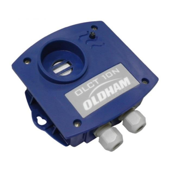
Figure 1: Component parts of an OLCT 10N Type of detector available Range Methane (CH 0-100% LEL (5% vol.) 0-100% LEL (4.4% vol.) Hydrogen (H 0-100% LEL (4% vol.) Butane (C 0-100% LEL (1,5% vol.) Propane (C 0-100% LEL (2% vol.) Oxygen (O 0-30% vol. -
Page 9: Chapter 2 | Installation
Do not cover the detector Do not paint the detector Avoid dust The OLCT 10N may be used only with the OLDHAM MX 43 or MX 32v2 measurement and alarm controller. versions are not certified to use in ATEX area... -
Page 10: Connection
MX 32v2 controller. RS485 transmission The OLCT 10N has 2 cable glands that are used for the input cable and the output cable to the next module. The detectors must be connected using MPI-22A cable type, minimum core size is 0.22 mm²... - Page 11 modules in the line and then to the corresponding line connector of the MX 43 or MX 32v2 controller. The cable shielding must be connected to a ground terminal. The 120 end-of-line resistor must be placed at the end of the line. This simply involves switch #8 being moved to the ON position on the last module (cf.
-
Page 12: Configuration Of Communication
The Addressing Table below lists the possible Figure Switches combinations. address configuration Switches Switches (ON = 1 ; OFF = 0) (ON = 1 ; OFF = 0) Table 1: Addressing table (address depends on switch positions) OLCT 10N User Manual... - Page 13 Remarks: ■ During module replacement, all the configuration switches of a new module must be positioned in the same configuration as those of the previous module. ■ Switch #6 (FRAME FILLING) must be set to OFF (unused option). ■ Switch #7 (DELAY) must be set to ON. End of line resistance For the last detector, set switch #8 (EOL RESISTOR) to ON.
-
Page 14: Scope Of Use
Scope of use The OLCT 10N may be used only with the OLDHAM MX 43 or MX 32v2 measurement and alarm controller. The sensors have certain limitations; it is essential to fully recognize these limitations. Presence of specific components Vapor from components containing silicone or sulfur can affect the catalytic sensors and thereby distort measurements. -
Page 15: Chapter 3 | Maintenance
ATEX marking shall be observed (see Chapter 8). When first powered up or after a sensor replacement, wait for 1 hour before performing a calibration. It is impossible to calibrate an OLCT 10N within 10 minutes after a power cycle. Maintenance Frequency Gas detectors are safety devices. -
Page 16: Semi-Automatic Calibration
1000 ppm NH Semi-automatic calibration While the OLCT 10N is calibrating, the MX 43 or the MX 32v2 inhibits alarms triggered by the detector and displays a maintenance code. Up to 32 sensors can be calibrated at the same time. - Page 17 LED is OFF Mode START Cal ON Inject zero air Cal OFF (Nitrogen in the case of an OLCT 10N O2) GREEN blinking and wait for stabilization Zero is stable Internal processing (20 to 60 s) GREEN steady Zeroing is complete...
- Page 18 Semi-automatic calibration device (P/N 6331163) OLCT 10N User Manual...
-
Page 19: Sensor Replacement
In order to comply with the ATEX rules, the sensor of LEL detectors is soldered to the card and cannot be changed separately. The entire OLCT 10N detector will need to be replaced. As the detector is factory calibrated, there is no point attempting manual calibration. -
Page 20: Manual Calibration
Ensure that the sensor is in clean air (in absence of O2 in the case of OLCT 10N O2). If not, inject zero air (Nitrogen in the case of an OLCT 10N O2) into the sensor at a flow rate of 1 l/min, then wait for voltmeter signal to stabilize (use the calibration gas kit: zero air cylinder, calibration cap, tube). - Page 21 SENS ZERO OLCT 10N OLCT 10N connector - P/N 6116291 MAINTENANCE WIRES: S- (grey) / S+ (yellow) = signal from 0 mV to 1600 mV for zero and sensitivity settings GND (black) = circuit board ground +VCC (red) = + power supply Note: Blue and green wires are not used.
- Page 22 OLCT 10N User Manual...
- Page 23 Chapter 4 | Part Numbers Accessories Part Number Description OLCT 10N-001 OLCT 10N Digital detector, range 0-100% LIE CH (5% vol.) OLCT 10N-002 OLCT 10N Digital detector, range 0-100% LIE CH (4.4% vol.) OLCT 10N-003 OLCT 10N Digital detector, range 0-100% LIE H (4% vol.)
- Page 24 OLCT 10N User Manual...
-
Page 25: Chapter 5 | Spare Parts
Chapter 5 | Spare Parts Spare parts list for the different detectors. Part Number Description 6798301 CO sensor 6314196 sensor - 5000ppm range 6314195 sensor - 5% vol range 6314197 sensor - 100% vol range 6313990 S sensor 6314118 sensor - 100 ppm range 6314119 sensor - 1000 ppm range 6113331... - Page 26 OLCT 10N User Manual...
-
Page 27: Chapter 6 | Ue Declaration
Chapter 6 | UE Declaration UE Declaration... - Page 28 OLCT 10N User Manual...
-
Page 29: Chapter 7 | Specifications
Chapter 7 | Specifications Detector Dimensions 118x110x63 mm Ingress protection IP65 Enclosure UV-resistant ABS Cable entries 2 cable glands, M16, outer diameter 4 to 8 mm Type of cable Type MPI-22A Power supply 12-30V Consumption (under normal Electrochemical sensor: 2.5 mA operating conditions @ 24 V) Catalytic sensor: 50 mA Infrared sensor: 20 mA... -
Page 30: Sensor Specifications
-20 to +55 Butane (0-70% LEL) -20 to +50 ± 3% 15/40 Carbon monoxide 1000 5000 18/32 -40 to +50 ± 3% 0-5% vol. 19/33 Carbon dioxide 0-100% vol. 13/22 -20 to +50 ± 3% 15/30 Hydrogen sulfide OLCT 10N User Manual... - Page 31 ± 5 ppm 25/70 -20 to +40 Ammonia 1000 ± 20 ppm 20/60 -20 to +50 ± 3% 10/30 Nitric oxide -20 to +50 ± 3% 30/60 Nitrogen dioxide (2 years) 0,4 Vol.% 0-30 Vol.% -20 to +50 6/15 Oxygen (15-22 %) (5 years) 0-30 Vol.%...
-
Page 32: Line Length (Use With Mx 32)
MX 32v2 controller. TOX and O MX 32v2 with internal 100-240Vac power supply or powered externally 24Vdc Distance in meters Line cross-section Number of OLCT 10N detectors used to 0.75 mm² 0.5 mm² 0.22 mm² detect toxic gases or oxygen (except CO... - Page 33 MX 32v2 with internal 100-240Vac power supply or powered externally 24Vdc Distance in meters Line cross-section 0.75 mm² 0.5 mm² 0.22 mm² Number of OLCT 10N detectors used to (AWG 18) (AWG 20) (AWG 24) detect CO 1000 1000 1000...
- Page 34 Catalytic MX 32v2 with internal 100-240Vac power supply Distance in meters Line cross-section 0.75 mm² 0.5 mm² 0.22 mm² Number of OLCT 10N detectors equipped (AWG 18) (AWG 20) (AWG 24) with a catalytic sensor (LEL versions) 1000 1000 1000 Maximum load for an MX 32V2 line (>610mA).
-
Page 35: Line Length (Use With Mx 43)
MX 43 controller. TOX and O With any MX 43 mother board version Distance in meters Line cross-section Number of OLCT 10N detectors used to 0.75 mm² 0.5 mm² 0.22 mm² detect toxic gases or oxygen (except CO... - Page 36 MX 43 with Rev. A or Rev. B mother board Distance in meters Line cross-section 0.75 mm² 0.5 mm² 0.22 mm² Number of OLCT 10N detectors used to (AWG 18) (AWG 20) (AWG 24) detect CO 1000 1000 1000 1000...
- Page 37 MX 43 with Rev. A or Rev. B mother board Distance in meters Line cross-section 0.75 mm² 0.5 mm² 0.22 mm² Number of OLCT 10N detectors equipped (AWG 18) (AWG 20) (AWG 24) with a catalytic sensor (LEL versions) 1000...
- Page 38 OLCT 10N User Manual...
-
Page 39: Chapter 8 | Specific Instructions For Use In Explosive
Directive 94/9/EC General comments OLCT 10N detectors comply with the requirements of European ATEX Directive 94/9/EC on Gas and Dust explosive atmospheres. OLCT 10N transmitter detectors are used to measure certain explosive or toxic gases or oxygen. They can be installed in ATEX zones 2 or 22 (except for CO versions which should be installed in safe area only). -
Page 40: Marking For Toxic Gas Or Oxygen Detector Versions
Marking for toxic gas or oxygen detector versions (except CO versions) The marking will be as follows: OLDHAM Arras OLCT 10N TOX II 3 GD Ex nA IIC T4 Gc Ex tc IIIC T135°C Dc IP 65 Amb. Temp.: -20°C to +55°C INERIS 11ATEX3023X IECEx INE 11.0029X... - Page 41 Specific instructions...
- Page 42 OLCT 10N User Manual...
- Page 44 The Fixed Gas Detection Experts EUROPEAN PLANT AND OFFICES Z.I. Est – rue Orfila CS 20417 – 62027 Arras Cedex FRANCE Tél: +33 (0)3 21 60 80 80 – Fax: +33 (0)3 21 60 80 00 Website: https://gasdetection.3m.com AMERICAS ASIA PACIFIC EUROPE Tel: +1-713-559-9280 Tel: +86-21-3127-6373...
Need help?
Do you have a question about the OLCT 10N and is the answer not in the manual?
Questions and answers