
Related Manuals for Oldham OLC 10


Summary of Contents for Oldham OLC 10
- Page 1 OLC 10 OLCT 10 User Manual Analog Gas Detector Non ATEX version Part Number : NPO10GB-NEX Revision : ZZ.1...
- Page 2 User Manuals in others language are available on Website https://teledynegasandflamedetection.com Copyright © December 2019 by OLDHAM SIMTRONICS S.A.S. All rights reserved. No reproduction of all or part of this document, in any form, is permitted without the written consent of Oldham Simtronics S.A.S.
-
Page 3: Table Of Contents
MOUNTING ..........................3 III. ELECTRICAL INSTALLATION OF DIFFERENT VERSIONS ........5 1. Connection of OLC 10, OLCT 10 EXPLO or OLCT 10 SC (Semi-Conductor) to a controller for combustible gas detection: ................5 2. Connection of two OLC 10 TWIN to a controller ..............6 3. - Page 4 OLDHAM SIMTRONICS products. OLDHAM SIMTRONICS shall not be responsible for any direct or indirect damage, or any direct or indirect consequence, resulting from the sale and use of any of its products UNLESS SUCH PRODUCTS HAVE BEEN SELECTED BY OLDHAM SIMTRONICS ACCORDING TO THE APPLICATION.
- Page 5 Destruction of the equipment European Union (and EEA) only. This symbol indicates that, in conformity with directive DEEE (2002/96/CE) and according to local regulations, this product may not be discarded together with household waste. It must be disposed of in a collection area that is set aside for this purpose, for example at a site that is officially designated for the recycling of electrical and electronic equipment (EEE) or a point of exchange for authorized products in the event of the acquisition of a new product of the same type as before.
-
Page 7: Presentation Of Different Versions
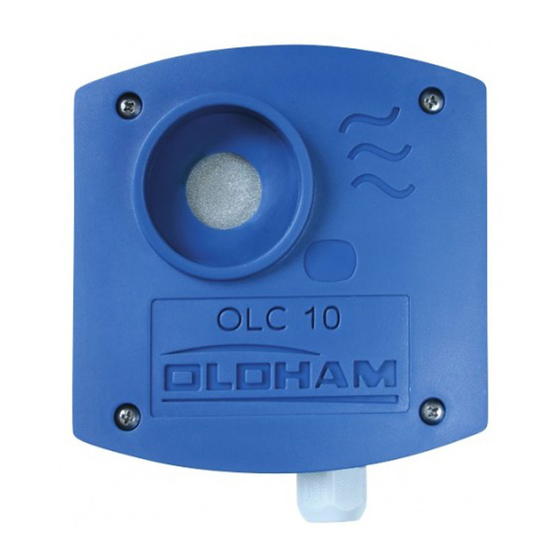
P R E S E N T A T I O N O F D I F F E R E N T V E R S I O N S The OLC 10, OLC 10 TWIN and OLCT 10 EXPLO combustible gas detectors are detectors fitted with catalytic sensors and intended for use in boiler rooms and parking lots. -
Page 9: Electrical Installation Of Different Versions
Conductor) to a controller for combustible gas detection: Notes: The controller configuration will be different based upon the use of an OLC 10 or OLCT 10 Cable to be used: 3 conductors, 3x1 mm² LiYCY type e.g., CONTROLLER MX 15... -
Page 10: Connection Of Two Olc 10 Twin To A Controller
Connection of two OLC 10 TWIN to a controller Cable to be used: 3 and 4 core cable, 3x1 mm² and 4x1 mm² LiYCY type Connect the 3 wires based on the corresponding numbering on the controller. MX 15 CONTROLLER... -
Page 11: Connection Of Two Olct 10 Tox (Maximum 5) To A Controller For Detection Of The Same Toxic Gas
Connection of two OLCT 10 TOX (maximum 5) to a controller for detection of the same toxic gas Cable to be used: One pair (0.75 mm²) screened cable Connect the 2 wires based on the corresponding numbering on the controller. CONTROLLER MX15 for example OLCT 10 TOX 3 1 3 1 3 1 3 1... -
Page 12: Controller
Connection of two OLCT 10 TOX networks (5 detectors max. per netw ork) for detection of two different toxic gases or monitoring of tw o conjoined areas to a tw o-channel controller Cable to be used: Two pairscreened cable (0.75 mm²) Example: one zone, 2 gases Detector 3 Detector 4... -
Page 13: Maintenance
60 l/h, then wait for the stabilisation of measurement Perform the zero setting of the controller (see manual of relevant product) Now inject the calibration gas (flow rate 60l/h) into the OLC 10 sensor and wait for signal stabilisation on the controller display If necessary, calibrate the sensitivity using the “S”... - Page 14 ZERO (4mA) potentiometer SENSITIVITY (20mA) potentiometer CHANGER-OVER Ref 2.5V S Signal Voltmeter + 4-20 mA - 4-20 mA +VDC MAINTENANCE CONNECTOR WIRES: +VDC/red = + power supply - 4-20 mA/blue = - of voltage, image of 4-20mA Read on the voltmeter 400mV for 4mA and 2000mV for 20mA + 4-20 mA/green = + of voltage, image of 4-20mA S Signal /yellow = signal from 0mV to 1600mV for zero and sensitivity setting voltmeter...
-
Page 15: Periodic Maintenance With Several Olct 10 Transmitters For Toxic Gas
Notes regarding the OLCT 10 version for combustible gases: the transmitter controls an “ambiguity resolution” function: if the sensor detects a gas concentration over 100% LEL (20 mA), it will be locked on a signal of 23.2 mA acknowledgeable through power supply shut-off or toggling of maintenance switch. -
Page 17: Technical Specifications
MX 15 controller - 1 cable gland M16: cable diameter 4 to 8 mm OLC 10 Twin Version (two sensors on channel input MX 15) - 1 3-wire terminal block to the controller - 1 4-wire terminal block to the second sensor - maximum total distance 300 m in 1.5 mm²... -
Page 18: Technical Specifications - Olct 10 Explo Transmitter
TECHNICAL SPECIFICATIONS - OLCT 10 Explo Transmitter Combustible gas transmitter Detection principle: Catalytic Range: 0-100% LEL methane, propane or butane. 4 – 20 mA, default 0.5 mA or 23.2 mA Signal output: signal sets at 23.2 mA if measurement 100% LEL Ambiguity resolution: Acquit by power cycling the transmitter Ambiguity resolution may be deleted through point of programming... -
Page 19: Technical Specifications - Olct 10 Co Transmitter
TECHNICAL SPECIFICATIONS - OLCT 10 CO Transmitter Detection principle: Electrochemical sensor Range: 0-300 ppm CO 4 – 20 mA Signal output: Settings: Local through Zero and Sensitivity potentiometers Position Maintenance 2 mA 6-pin connector for gas measuring and current image (100-ohm shunt) Power supply: 15 to 30 VDC... -
Page 20: Technical Specifications - Olct 10 Sc Transmitter
TECHNICAL SPECIFICATIONS - OLCT 10 SC Transmitter Detection principle: semi-conductor sensor Range: 0-2000 ppm R134A, R22 4 – 20 mA Signal output: Settings: Local through Zero and Sensitivity potentiometers Position Maintenance 2 mA 4-pin connector for gas measuring and current image (100-ohm shunt) Power supply: 15 to 30 VDC... -
Page 21: Technical Specifications - Olct 10 No Transmitter
TECHNICAL SPECIFICATIONS - OLCT 10 NO Transmitter Detection principle: electrochemical sensor Range: 0-100 ppm NO 4 – 20 mA Signal output: Settings: local through Zero and Sensitivity potentiometers Position Maintenance 2 mA 4-pin connector for gas measuring and current image (100-ohm shunt) Power supply: 15 to 30 VDC... -
Page 22: Technical Specifications - Olct 10 No2 Transmitter
TECHNICAL SPECIFICATIONS - OLCT 10 NO2 Transmitter Detection principle: electrochemical sensor Range: 0-30 ppm NO2 4 – 20 mA Signal output: Settings: local through Zero and Sensitivity potentiometers Position Maintenance 2 mA 4-pin connector for gas measuring and current image (100-ohm shunt) Power supply: 15 to 30 VDC... -
Page 23: Detail Specifications For Use
V I . D E T A I L S P E C I F I C A T I O N S F O R U S E Special precautions ▪ Sensors are sensitive to some poisons that may cause their desensitisation: emanation of siliconized vapours with concentrations >... -
Page 25: Declarations Of Conformity
V I I . D E C L A R A T I O N S O F C O N F O R M I T Y... - Page 28 Pour toute intervention de notre Service Après-Vente en France, contactez-nous gratuitement par téléphone 0 800 653 426 (choix n°1) ou par email à oldham-servicecenter@mmm.com. Z.I. Est – rue Orfila CS 20417 – 62027 Arras Cedex FRANCE Tél: +33 (0)3 21 60 80 80 – Fax: +33 (0)3 21 60 80 00 Website: https://teledynegasandflamedetection.com...
Need help?
Do you have a question about the OLC 10 and is the answer not in the manual?
Questions and answers