
Related Manuals for Oldham OLC 100


Summary of Contents for Oldham OLC 100
- Page 1 OLC/OLCT 100 USER M ANUAL Gas Detector Part Number: NPO100GB Revision: L.6 The Fixed Gas Detection Experts...
- Page 2 All rights reserved. No reproduction of all or part of this document, in any form, is permitted without the written consent of Oldham Simtronics S.A.S. All of the information that is provided in this document is accurate to the be s t of our knowledge.
-
Page 3: Table Of Contents
Composition of the detector ............... 10 Internal elements................11 Identifiers ..................12 Chapter 2 | Ranges ..............13 OLC 100 and OLCT 100 ranges ............13 Chapter 3 | Installation ............15 Regulations and conditions of use ............15 Necessary equipment ................ 15 Electrical power supply .............. - Page 4 Chapter 7 | Accessories ............41 Cable gland ..................44 Chapter 8 | Spare parts............45 Chapter 9 | Declarations of EU conformity ......47 Chapter 10 | Technical specifications ........53 Dimensional characteristics ..............53 General Specifications ............... 54 Catalytic sensor (OLCT 100 XP ) ............
- Page 5 OLDHAM SIMTRONICS does not support or authorise any business, person, or legal entity in assuming responsibility on behalf of OLDHAM SIMTRON IC S , even though they may be involved in the sale of OLDHAM SIMTRONICS products.
- Page 6 Warning This is not a contractual document. In the best interest of its customers and with the aim of improving performance, OLDHAM SIMTRONICS reserves the right to alter the technical features of its equipment without prior notice. READ THESE INSTRUCTIONS CAREFULLY BEFORE THE FIRST USAGE: these instructions should be read by all persons who have or will have responsibility for the use, maintenance, or repair of the instrument.
- Page 7 Guarantee Under normal conditions of use and on return to the factory, parts and workmanship are guaranteed for 3 years, excluding such consumables as sensors, filters, etc. Destruction of the equipment European Union (and EEA) only. This symbol indicates that, in conformity with directive DEEE (2002/96/CE) and according to local regulations, this product may not be discarded together with household waste.
- Page 8 OLC(T) 100 User manual...
-
Page 9: Chapter 1 | Presentation
(as with the OLC 100 explosimeter) that operates on the principle of the Wheatstone bridge. Such a measurement unit is available in the OLDHAM SIMTRONICS range. -
Page 10: Composition Of The Detector
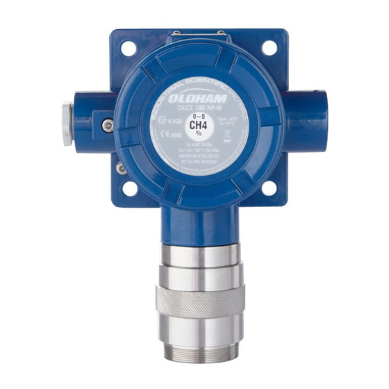
Composition of the detector A detector comprises the following elements: Description Company label Cover PCB protector (for OLCT version). PCB. Cable gland inlet. (cable gland not supplied). Enclosure. Sensor block. Nozzle. Ground connection. LEL sensor (high temperature). Figure 1 : com ponent parts of an OLCT 100 detector OLC(T) 100 User manual... -
Page 11: Internal Elements
Sensor block connector. Calibration ribbon connector. 4 mA adjustment. Push button access for 4 mA adjustment. Zeroing. Sensitivity adjustment. OLC 100 detector OLCT 100 explosimeter OLCT 100 detector for toxic gases Figure 2 : internal view of the detectors 1 - Presentation... -
Page 12: Identifiers
Description Manufacturer's name Name of product ATEX Marking CE symbol and the number of the 0-100% LIE organisation that provided the OLDHAM SIMTRONICS production quality certification (INERIS Warning Type of gas detected and range of measurement Figure 3 : Firm plate (example) -
Page 13: Chapter 2 | Ranges
Chapter 2 | Ranges OLC 100 and OLCT 100 ranges The OLC 100 range is reserved for the detection of explosive vapor by using a Wheatstone bridge sensor. The OLCT 100 range of detectors is provided with an amplifier producing a 2 o r 3 wire 4-20 mA analog output. - Page 14 OLC(T) 100 User manual...
-
Page 15: Chapter 3 | Installation
Chapter 3 | Installation It is recommended that the guides relating to the installation, use, and maintenance of flammable gas and oxygen detectors (standard EN/IEC 60079- 29-2) and toxic gas detectors (standard EN 45544-4) should be clearly understood. Installation shall be in accordance with the standards in forc e, classification of the zone, and in conformity w ith standards EN/IEC 60079-14 and EN/IEC 61241-14, the editions in force, or w ith other national and/or local standards. -
Page 16: Electrical Power Supply
OLCT 100 IS EC 11 to 32 23,5 OLCT 100 XP SC 15,5 to 32 1550 By Oldham Simtronics OLC 100 (VQ1) controller By Oldham OLC 100 (4F) Simtronics controller (1) Depends on the gas controller Location of the detector... -
Page 17: Connector Cable
Installation of the enclosure shall be secured with 4 x M6 screws and the appropriate plugs for the supporting material Figure 6 : fixing tem plate for the enclosure A special holder is available for mounting the detector on the ceiling (see s e cti o n on accessories. -
Page 18: Cable Connection
Type of detector Type of sensor Maximum length (km) for Maximum cable of cross-section as load indicated resistance for 4-20 Ma 0, 5 mm² 0, 9 mm² 1,5 mm² Upstream l i n e vol t age (Vcc) Catalytic or OLCT 100 XP semiconductor OLCT 100 XP (1) - Page 19 Cable preparation The cable shall be taken from the controller (measurement and automation) to th e point of measurement (see Figure 8). The passage, support, and protection of th e cable shall be according to best practice. Cable entry The detector is supplied w ithout cable gland. It is essential that the instructions provided by the manufacturer of the compression gland are follow ed and the braided screen is correctly connected.
- Page 20 4 - Insert the part back into the OLCT100 and then mount the cable gland (not supplied). Cable connection The connection of the cable betw een the detector and controller should be made w ith the pow er off. The site should be at equal potential Connect the cable to the detector side before connecting the controller side.
- Page 21 Figure 9: connection for an intrinsically safe, 2-w ire 4-20 Ma detector with a Z e n er diode Figure 10: connection for a 3-w ire 4-20 Ma detector Figure 11: connection for a 3-w ire OLC 100 type detector 3 - Installation...
- Page 22 Connecting the enclosure to ground Connect the enclosure ground terminal to earth according to the regulations. Th i s ground connection may, however, be taken from the terminal on the screw fixing the PCB to the inside of the housing. Figure 12 : Ground connection terminal Closing the cover Before connecting the cable to the terminal on the controller, it is essential that the...
-
Page 23: Chapter 4 | Calibration
Chapter 4 | Calibration The tasks described in this chapter are reserved for authorised trained personnel only, since these tasks are liable to affect detection reliability This procedure describes: zero adjustment; Sensitivity adjustment. Necessary equipment Multimeter (ranges 0-30 mA and 0-2 V), intrinsically safe if necessary. Cylinder of pure air. -
Page 24: Stabilization Time
Stabilization time After mounting, it is essential to allow the detector temperature to stabilize. In addition, after turning the power on, certain sensors require a further pre-h e a ti n g time. Any adjustment before the time indicated will result in an incorrect measurement, which may in turn compromise the safety of the goods and personnel. -
Page 25: Calibrating The Olc 100
30 by using the recommended gas and corresponding coefficient. Zeroing Proceed as follows : Figure 13 : Zeroing (OLC 100) 1. Inhibit any alarm signals on the controller. 2. Place the calibration cup onto the detector head (Figure 13, "A"). - Page 26 Adjustment of gas sensitivity This procedure takes place after the zeroing stage: 1. Inhibit any alarm signals on the controller. 2. Place the calibration cup on the detector head (Figure 13, "A"). 3. Connect the calibration cup to the calibration gas cylinder "D" by using a flexible hose "B".
-
Page 27: Calibrating The Olct 100
Calibrating the OLCT 100 Wait for the stabilization time on power-up. For a LEL detector, it is recommended to calibrate with the targeted gas. Should the operator calibrate with another gas, please refer to tables on pages 28 to 30 to know the recommended calibration gas and the cross sensitivity factor. - Page 28 7. After the measurement has stabilized (approx. 2 minutes), read the value on the multimeter "B". A measurement of 0.4 V corresponds to 4 mA, i.e. 0% gas. Note: for the oxygen detector, inject pure nitrogen instead of air. 8. If a different value is displayed, adjust the "0" control ("C") in order to correct the value until 0.4 V is exactly displayed.
- Page 29 Use the following formula to determine the voltage value that is to be displayed : 1600 �� ���������������������� ������ �������������������������� Voltage displayed (mV) = 400 + ���������������� ���������� For example, for a range of 1000 ppm CO with a calibration gas cylinder of 300 ppm, the voltage displayed will be: 1600 ��...
- Page 30 Calibration coefficients of explosive gases for catalytic detectors When a VQ1 type sensor is used (available for OLC 100 and OLCT 100), the coefficients are as follows: Chemical Flash Vapor Coefficient Coefficient Coefficient Coefficient C a libr a tion ga s...
- Page 31 Chemical Flash Vapor Coefficient Coefficient Coefficient Coefficient C a libr a tion ga s C a libr a tion ga s C a libr a tion ga s C a libr a tion ga s Formula point (°C) density C H 4 (m e tha ne ) H 2 (H y dr oge n) C 4 H 1 0 (B uta ne ) C 5 H 1 2 (Pe nta ne )
- Page 32 When an anti-poison 4F type sensor is used (only available for OLCT 100), the coefficients are as follows: Chem ical LEL % Vapor Form ula density Coef Coef Coef Acetone 2.15 13.0 Acety lene Ammoniac 15.0 30.2 Benzene C6H6 2.10 1.05 n-Butane C4H10...
-
Page 33: Chapter 5 | Preventive Maintenance
(humidity, temperature, dust, etc.); however, it must not exceed one year. The general manager should put safety procedures in place on -site. OLDHAM SIMTRONICS cannot be held responsible for their enforcement. -
Page 34: Actions
Actions Periodic maintenance comprises the following actions: Removal of dust from the sensor’s protective housing, using only a dry cloth. No water or solvents should be used. Severely dusty heads or sensors should be replaced immediately. For use in dusty explosive atmospheres, the user should undertake full and regular cleaning to avoid the build-up of dust. -
Page 35: Chapter 6 | Maintenance
The 4 mA level is factory-set. This value cannot be changed or adjusted. This check does not concern explosimeter OLC 100. Opening the cover This stage is necessary for the 4 mA check, zeroing, and calibration of the detector. -
Page 36: Checking The Current Generator
Checking the current generator Although this setting is made in the factory, it is possible that the tran smitter and controller may have to be matched. In this case, proceed as follows Figure 15: checking the current generator 1. Insert the blue and green plugs on the measurement lead into the + and – multimeter sockets, respectively. -
Page 37: Possible Errors
Possible errors The table below summarizes the various possible detector errors : OLC 100 explosim eter Observed fault Possible cause Action Zero setting not Sensor Replace the sensor possible Cable Check cable Main unit detector module Check module Sensitivity Sensor... - Page 38 OLCT 100 Detector Observed fault Possible cause Action Line current 0 mA Connector cable Check cable Pow er supply Check voltage Replace the PCB Line current < 1mA Pow er the detector dow n then pow er it up (Off/On) Replace the sensor Sensor Replace the PCB...
-
Page 39: Replacing Sensor Block
Replacing sensor block Standard Version First follow the instructions in the section Opening the cover The sensor block encloses the actual detector sensor itself. A sensor block can only be associated with a defined detector. A guide pin ensures that the sensor block g o e s together correctly Figure 16: The sensor block (the black com ponent) - Page 40 High temperature version Proceed as follows for the high temperature version. Inhibit any alarm signals on the controller. Switch off the supply to the detector. Loosen the maintenance screw (Figure 17, "B") on the detector head cover and remove it. Replace the defective detector head and replace the maintenance screw "B"...
-
Page 41: Chapter 7 | Accessories
Chapter 7 | Accessories Accessory Utilization Illustration Reference Tools kit Tool kit for OLCT 100 6147879 including calibration cup, Allen key, sensor removal key and connector cable humidifier kit Used for the calibration of the 6335918 semi-conductor transmitters Calibration cup Facilitates the injection of 6331141 calibration gas on the sensor Plastic material. - Page 42 Accessory Utilization Illustration Reference Stainless steel Protects the detector against 6129010 Splash-guard splashes Effect on measurement: no effect. Effect on response time: response time for natural diffusion can increase for certain gases. Contact us for details. Remote Enables the detection of 6327911 calibration cup ambient gases simultaneously...
- Page 43 Accessory Utilization Illustration Reference Sunshield Protects any detector 6123716 mounted on the outside of a building. Effect on measurement: no effect. Effect on response time: negligible. Wall mounting Allow s the sensor to detect 6331169 gas collector more quickly the gas. (Wall mounting) Effect on measurement: no effect.
-
Page 44: Cable Gland
Cable gland Purpose Reference M20 cable gland for non-armoured cable 6343493 Material: stainless steel M20 cable gland for non-armoured cable 6343499 Material: Nickel-plated brass (not recommended for use w ith ammonia or acetylene) M20 cable gland for armoured cable 6343489 Material: stainless steel M20 cable gland for armoured cable. -
Page 45: Chapter 8 | Spare Parts
Chapter 8 | Spare parts List of spares for the various detectors Part Num ber Description Catalytic sensor 0-100% LEL VQ1 for OLC 100 and OLCT 100 6 314 010 (Standard version only) Catalytic sensor 0-100% LEL 4F for OLCT 100 (poison resistant 6 313 994 version only. - Page 46 Semiconductor sensor for ethanol, toluene, isopropanol, 2-butanone 6 314 039 and xylene for OLCT 100 6 451 626 OLC 100 Board 6 451 646 OLCT 100 IR Board (CO 6 451 700 OLCT 100 IR Board (R1234yf, R134a, R407f and SF6)
-
Page 47: Chapter 9 | Declarations Of Eu Conformity
Chapter 9 | Declarations of EU conformity The document hereafter (2 pages) reproduces the EU declaration of conformity. 9 – Declarations of EC conformity... - Page 48 OLC(T) 100 User manual...
- Page 49 9 – Declarations of EC conformity...
- Page 50 The document below (1 page) reproduces the 96/98/EC Marine Directive declaration of conformity. OLC(T) 100 User manual...
- Page 51 9 – Declarations of EC conformity...
- Page 52 OLC(T) 100 User manual...
-
Page 53: Chapter 10 | Technical Specifications
Chapter 10 | Technical specifications Dimensional characteristics M44 pitch 1 M44 pitch 1 M44 pitch 1 Figure 18: dim ensional characteristics of the detectors 10 – Technical specifications... -
Page 54: General Specifications
General Specifications Supply voltage at the detector OLC 100 : 340 mA (current supply) terminals (Vdc) : OLCT 100 XP HT : 15.5 V to 32 V OLCT 100 XP LEL : 15.5 V to 32 V OLCT 100 XP IR : 13.5 V to 32 V OLCT 100 XP EC : 11 V to 32 V OLCT 100 XP SC : 15.5 V to 32 V... -
Page 55: Catalytic Sensor (Olct 100 Xp)
(sensor with OLCT 100 : 2% of the measurement between 71 and identifying mark) 100% LE L OLC 100 : 5% of the measurement between 71 and 100 % LE L 1% LEL betw een 0-70%LEL VQ1 sensor, high -20 to +200°C... -
Page 56: Toxic Sensors (Olct 100 Xp And Olct 100 Is)
Mark on sensor VQ1 4F poison resistant sensor Figure 19: m ark on VQ1 sensor Toxic sensors (OLCT 100 XP and OLCT 100 IS) Common characteristics Measurement principle : Electrochemical sensor Pressure : Atmospheric ± 10% OLC(T) 100 User manual... - Page 57 Measurement IS Version Temperature Accuracy Lyfe Reponse Storage Warm- Type of gas % RH range Version range °C (ppm) (months) time conditio up time (at 20°C) max (h) (ppm) Arsine 1.00 -20 to +40 20 - 90 +/- 0.05 30/120 Formaldehy de 50.0 -20 to +50...
- Page 58 Measurement IS Version Temperature Accuracy Lyfe Reponse Storage Warm- Type of gas % RH range Version range °C (ppm) (months) time conditio up time (at 20°C) max (h) (ppm) +/- 5 50/90 Ammonia 1,000 -20 to +40 15 - 90 +/- 20 50/90 5,000...
-
Page 59: Semiconductor Sensors (Olct 100 Xp)
Semiconductor sensors (OLCT 100 XP) Common characteristics Measurement principle : semiconductor Temperature range : -20°C to +55°C Relative humidity : 20 to 95% RH (non-condensing relative humidity) Pressure : atmospheric ± 10% Lifetime (typical) : 40 months Storage conditions : -20 to 50 °C, 20 to 60% RH, 1 bar ±... -
Page 60: Infrared Sensors (Olct 100 Xp-Ir)
Infrared sensors (OLCT 100 XP-IR) Measurement range : 0-100% LEL R1234yf 0-2000 ppm R1234yf, R134a, R407f, SF 0 – 5000 ppm CO (carbon dioxide) 0 – 5% CO (carbon dioxide) 0 – 10% CO 0 – 100% CO Measurement principle : - Infra-red absorption Pressure : 1 bar ±... - Page 61 Measurement XP Version Temperature Accuracy Lyfe Reponse Storage Type of gas % RH range range °C (ppm) (months) time conditions m-up time (ppm) 5,000 +/- 150 +/- 0.15% 15 - 90 carbon dioxide -25 to +50 15/30 +/- 0.3% 100% +/- 3% +/- 40 (from 0 to 50% FS) 2,000...
- Page 62 OLC(T) 100 User manual...
-
Page 63: Chapter 11 | Specific Instructions For Use In Explosive Atmospheres And Operational Safety
Chapter 11 | Specific instructions for use in explosive atmospheres and operational safety General comments OLC/OLCT 100 conforms to the requirements of European Directive ATEX 2014/34/UE relating to explosive Dust and Gas atmospheres. On account of th e i r metrological performance as tested by the accredited organization INERIS (in process), the OLC/OLCT 100 transmitter detectors intended for the measuremen t of explosive gases are classed as safety devices in the sense of the European... -
Page 64: Cable Entries
Directive and may, therefore, contribute to limiting the risks of explosion. For this to be so, they must be connected to Oldham Simtronics type MX 15, MX 32, MX 42A, MX 48, MX 43, MX 52 or MX 62 detection controllers, or connected to measuring systems that are certified according to IEC / EN standards 60079-29-1 and compatible with their characteristics (see transfer curve). -
Page 65: Transfer Curve
If the user connects the Fault transmitter to a controller other than provided Oldham Simtronics, they should be certain that the transfer curve is fully compatible with the input characteristics of their equipment to ensure the proper... -
Page 66: Functional Safety
Functional safety The detector is certified by INERIS (in process) to be in conformity with the requirements of standard EN 50402 for SIL capability 1 and 2 for the CH and H C versions. Applicable since 2005, this standard is concerned with electrical apparatuses for the detection and measurement of oxygen or toxic or flammable gases or vapors, and defines the requirements relating to the safety function of fixed gas detection systems. -
Page 67: Special Conditions Of Use
Special conditions of use In case of exposure above the measuring range, it is mandatory to bump test the instrument with gas and/or to perform a calibration. In the event of a change of position, it is necessary to re -calibrate the detector. - Page 68 OLC(T) 100 User manual...
-
Page 69: Appendix | Ordering Information
Appendix | Ordering information Gas List Please find below the list of gases that the OLC/OLCT 100 detector can detect. Gas Code Methane 0-100 % LEL Methane 0-100% LEL (4.4% vol) Hydrogen 0-100% LEL Butane 0-100% LEL Propane 0-100% LEL Ammoniac 0-100% LEL Ethyl Acetate 0-100% LEL Butyl Acetate 0-100% LEL... - Page 70 Gas Code Diesel 0-100% LEL Natural gas 0-100% LEL Heptane 0-100 % LEL Hexane 0-100% LEL Isobutane 0-100% LEL Isobutene 0-100% LEL Isopropanol 0-100% LEL Kerosene (JP4) 0-100% LEL Methyl Methacrylate 0-100% LEL Methanol 0-100% LEL Methylamine 0-100% LEL Naphta 0-100% LEL Naphtalene 0-100% LEL Nonane 0-100% LEL Octane 0-100% LEL...
- Page 71 Gas Code NO, 0-100 ppm NO, 0-300 ppm NO, 0-1,000 ppm , 0-10 ppm , 0-30 ppm , 0-10 ppm SO2, 0-30 ppm , 0-100 ppm , 0-10 ppm , 0-2,000 ppm HCl, 0-30 ppm HCl, 0-100 ppm HCN, 0-10 ppm HCN, 0-30 ppm , 0-100 ppm , 0-300 ppm...
- Page 72 Gas Code R11, 0-1% volume R23, 0-1% volume Dichloromethane, 0-500 ppm Chloromethane (Methylchloride), 0-500 ppm R123, 0-2,000 ppm FX56, 0-2,000 ppm R143a, 0-2,000 ppm R404a, 0-2,000 ppm R507, 0-2,000 ppm R410a, 0-1,000 ppm R32, 0-1,000 ppm R407c, 0-1,000 ppm R408a, 0-4,000 ppm R407f, 0-1,000ppm R407f, 0-2,000ppm , 0-2,000ppm...
- Page 73 Appendix...
- Page 74 OLC(T) 100 User manual...
- Page 75 Appendix...
- Page 76 The Fixed Gas Detection Experts EUROPEAN PLANT AND OFFICES Z.I. Est – rue Orfila CS 20417 – 62027 Arras Cedex FRANCE Tel: +33 (0)3 21 60 80 80 – Fax: +33 (0)3 21 60 80 00 Website: https://gasdetection.3m.com AMERICAS ASIA PACIFIC EUROPE Tel: +33-321-608-080 Tel: +1-713-559-9280...
Need help?
Do you have a question about the OLC 100 and is the answer not in the manual?
Questions and answers