Oldham SV 4B User Manual
Gas surveyor
Hide thumbs
Also See for SV 4B:
- User manual (36 pages) ,
- Installation, operating and maintenance manual (20 pages)

Related Manuals for Oldham SV 4B


Summary of Contents for Oldham SV 4B
- Page 1 Surveyor 4B User Manual Part Number: NPS4BGB Version: C The Fixed Gas Detection People...
- Page 3 * None of this information may be reproduced, copied, divulged or translated, by physical, electronic or any other means, nor used as the basis for the manufacture or sale of OLDHAM equipment or for any other reasons without prior consent from OLDHAM.
- Page 4 The values indicated must not be exceeded in any circumstances. This is not a contractually binding document. In the interest of its customers, OLDHAM reserves the right to make any changes, without notice, to the technical characteristics of its equipment in order to improve performance levels.
-
Page 5: Table Of Contents
Contents I. DESCRIPTION II. MOUNTING OF THE SURVEYOR 4B III. CONNECTIONS 3.1. Alternative power supply 3.2. DC power supply 3.3. Explosimetric detectors 3.4. External components 3.5. Examples of installation IV. OPERATING INSTRUCTIONS 4.1. Switching on 4.2. Switching off 4.3. Alarms 4.3.1. -
Page 7: Description
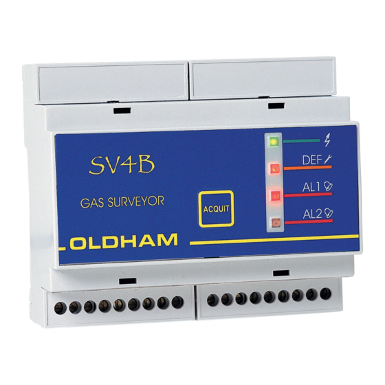
I. DESCRIPTION Surveyor 4B is equipped with a small "NORMAL" box (58 x 105 x 90 mm). It can be snap-fastened onto a standard symmetrical DIN rail and is easily integrated in an electric equipment cabinet. The components used in operation are located on the front of the appliance: adjustments and tests on the top (item 1), indicator lights on the FRONT face (item 2), connections at the bottom (item 3). -
Page 9: Connections
III. CONNECTIONS Electrical connections must be made by a specialist and must comply with the regulations in force. They must also be in conformance with standard NF C 15-100. The nature of the current and line voltage must be checked. The line voltage must match the voltage specified on the plate fitted on the Surveyor 4B. -
Page 10: Explosimetric Detectors
Relay 1 (REL 1), which is in mode, corresponds to the first gas alarm threshold and to the "FAULT" alarm. This relay is equipped with SPDT contacts available on the SV 4B terminal block (item 3, Fig. Relay 2 (REL 2), which is "negative safety" mode, corresponds to the second gas threshold only. -
Page 11: Examples Of Installation
OLC twin 2 Breaking capacity of rating relays switch contact : 120VA ou 30W Important: The relay's contacts are shown on the SV 4B label, unit switch off. The AL1/ DEF relays are normally energized and the AL2 relay is unenergized. - Page 12 1 2 3 Detector Breaking capacity of rating relays switch contact : 120VA ou 30W Important: The relay's contacts are shown on the SV 4B label, unit switch off. The AL1/ DEF relays are normally energized and the AL2 relay is unenergized.
-
Page 13: Operating Instructions
It is assumed that all the necessary connections have been made and that the whole installation complies with the standards currently in force. As soon as the SV 4B is supplied with power, it is ready to use and the GREEN light-emitting diode lights up (item 1, Fig. 6). -
Page 14: Fault Alarms
4.3.2. FAULT alarms The SV 4B is equipped with a fault alarm (visual alarm (item 2, Fig. 6), audio alarm and relay 1) which is activated in the following cases: One or more wires of the telemetry line interrupted, ... -
Page 15: Adjusting The "Gas Alarm" Thresholds
4.4.1. Adjusting the "gas alarm" thresholds Using a "reference gas kit" (gas cylinder + pressure regulator, etc.), inject the reference gas with a content level higher than the first threshold desired. (For example, threshold 1 will be 20% LEL, so a minimum of 25% LEL should be injected). -
Page 16: Acknowledgement Of Gas Alarms
If you wish to lock the alarm relays (inhibiting the relays) during these alarm threshold adjustments: set the maintenance switch to the high position (item 2, Fig. 7). Maintenance Normal Caution: When the adjustments have been made, do not forget to place the switch back in its normal position. -
Page 17: Adjusting The Zero
4.4.3. Adjusting the ZERO Necessary when a cell is replaced. At least twice a year. Connect a voltmeter to the two terminal posts provided for that purpose (MF and MES), as shown below. Rep 3 Rep 2 Rep 1 FIGURE 8 Be sure to be in pure atmosphere (without gas) (If not, inject air) Adjust the ZERO (0 mV) with the potentiometer, item 1.Figure8 4.4.4. - Page 18 Inject reference gas with content > threshold Alarm 1 triggered? Cell sensitivity is satisfactory Cell sensitivity is inadequate Can AL 1 be triggered by adjusting the alarm potentiometer (item 2, Fig. 8)? Cell sensitivity is inadequate: Cell sensitivity is now satisfactory. replace the cell and repeat calibration (O/S).
-
Page 19: Replacing The Fuse
4.5. Replacing the fuse It is mandatory that spare parts must be guaranteed original OLDHAM parts as, otherwise, the reliability of the equipment could be adversely affected. The fuse (Fig. 9, item 1) must be replaced by qualified personnel only. -
Page 21: Technical Specifications
The user thus has the obligation to separate the SV 4B of the other waste so as to guarantee that it is recycled in a sure way at the environmental level. For more details of the existing sites of... -
Page 22: Ec Declaration Of Conformity
VII. EC DECLARATION OF CONFORMITY... - Page 24 The Fixed Gas Detection People Ex-Ox-Tox Gasdetectie Westerdreef 5V 2152 CS Nieuw-Vennep Telefoon: 0252 620885 E-mail: info@exoxtox.n Website www.exoxtox.nl...
Need help?
Do you have a question about the SV 4B and is the answer not in the manual?
Questions and answers