
Related Manuals for Oldham MX62


Summary of Contents for Oldham MX62
- Page 2 OLDHAM SA GAS AND FLAME DETECTION STACK GAS AND DUST MONITORING We thank you for choosing an OLDHAM SA instrument. We have taken every step to ensure that this equipment continues to give you complete satisfaction. Please read the instruction manual carefully before using the instru-...
- Page 3 OLDHAM SA does not allow or authorize any company, person or legal entity to as- sume such responsibility on the part of OLDHAM SA, even if involved in the sale of the products of OLDHAM SA.
-
Page 4: Table Of Contents
THE SYSTEM WINPRO®..............7 1.1. THE MX62 SYSTEM BRIEFLY ................8 1.2. THE MX62 SYSTEM SYNOPSE ................9 1.3. MX62 SYSTEM : FUNCTIONAL DRAWING............10 CONFIGURATION ................11 2.1. DESCRIPTION OF MODULES................12 2.1.1. Controller Module (CM) ................12 2.1.2. - Page 5 MAINTENANCE ................... 32 5.1. CALIBRATION AND ADJUSTMENT ..............32 5.1.1. Direct Calibration at the Transducer ............32 5.1.2. Remote Calibration for Standard Transducers ..........32 5.1.3. Automatic Calibration of Transducer TBGW EX........33 5.1.4. Remote Calibration of Transducer TBGW EX ..........33 5.2.
-
Page 6: The System Winpro
1. The System WinPro® The system WinPro® is a stationary gas control unit to be used in combination with a variety of transducers for continuous detection of combustible and toxic gases. Main features are high reliability as well as remarkable flexibility. This flexibil- ity refers to all areas, such as free programmability and placing of relays and analog outputs as well as optional installation in wall-mounted housings, 19”- racks or control panels. -
Page 7: The Mx62 System Briefly
1.1. The MX62 system briefly MX 62 / ® WinPro For 64 detectors maximum Central unit, with redundant controllers, composed of : • main module, CPU with 2 processors • Panel* with alarm LED(s) and keyboard Input side : •... -
Page 8: The Mx62 System Synopse
1.2. The MX62 System synopse Del Panel LCD Panel + events memory Distant LCD Panel Controller A Controller B RS232 control interface Plant format Auxiliaries interfaces On field Bus RS485 converted output MODBUS or PROFIBUS formats Centronics printer interface... -
Page 9: Mx62 System : Functional Drawing
1.3. MX62 system : functional drawing INPUTS DETECTORS OUTPUTS 128 relays / 64 analog. Remote modules Local modules Input module I Module 1 to 8 / 8 to 16 relays 4..20 mA analog. + RS 485 (maintenance) Controller A Module II... -
Page 10: Configuration
2. Configuration The system consists of a controller module plus various other modules linked by digital bus. Basic configuration is as follows: Analog Input Module (AEM) • Controller Module (CM) • LED Module • The analog input module converts the 4-20mA of the transducers into digital bus signals to be transmitted to the controller module where these are evaluated and separately indicated for each channel according to the respective presetting. -
Page 11: Description Of Modules
2.1. Description of Modules 2.1.1. Controller Module (CM) The controller module is the central control unit of the system for all 64 chan- nels of maximum configuration. The values measured and conveyed to the ana- log input module are redundantly processed by two synchronously working 16- bit microcontrollers. -
Page 12: Analog Input Module (Aem)
2.1.2. Analog Input Module (AEM) The transducers are connected through the analog input modules. Each module accommodates up to any eight transducers of 4-20mA and provides an addi- tional RS 485 interface per channel. Via this interface, communication can be established during maintenance between a PC connected to the controller mod- ule and the respective transducer. -
Page 13: Led Module
2.1.3. LED Module The status of every channel is indicated by LEDs. (One transducer can be con- nected to each channel.) Operation of the key buttons for the respective channels displays additional information on the relevant transducers on the LCD module and triggers further functions such as alarm suppression, operational test, chan- nel disconnection and calibration mode. -
Page 14: Basic Relay Module (Rbm) And Extension Relay Module (Rem)
2.1.4. Basic Relay Module (RBM) and Extension Relay Module (REM) Dim (lg. 160 x h;90 x e.100) Output relays modules Basic module with 8 re- lays (lg.195 x h. 90 x e. 70) (RBM) ref : 6124880 Extension of 8 relays (lg. - Page 15 A basic relay module has eight relays and can be extended by a further eight re- lays through a pluggable extension relay module. Redundant triggering of the relays is via two 8-bit microcontrollers. Free param- eterization of the relays with the aid of the software ConfigPro meets all indi- vidual requirements: •...
-
Page 16: Analog Output Module (Aam)
2.1.5. Analog Output Module (AAM) The employment of up to eight analog output modules with a total of 64 outputs allows transmission of transducer signals (4-20mA or 0-10V). An address of 1-8 is allocated to each module by rotary switch. -
Page 17: Lcd Module
2.1.6. LCD Module The system WinPro® can be equipped with a graphic LCD display (240 x 128 pixels) showing, for example, information on measuring points, all relevant sys- tem parameters as well as system events and histograms. The LCD module is provided with an integrated data logger having a storage capacity of up to 32 Le panneau LCD esclave, distant, n’est pas équipé... -
Page 18: Adapter Module (Numeric Loop)
2.1.8. Adapter module (numeric loop) • This adaptator module is the interface between the controller module "CMN" (CPU) and the numeric loop. On this numeric loop, it will be possible to connect directly : Up to 16 numeric and addressable transmitters, Or 2 analogical input modules Or 16 analogical transmitters connected to the numeric loop thanks to "address boxes". -
Page 19: Description Of Redundancy
2.2. Description of Redundancy The redundant structure of the system WinPro® means that the complete safety functions are provided twice. From conversion of the analog signals into bus signals to evaluation in the controller module and relay connection, any single error will not lead to failure of the safety functions. -
Page 20: Operation Of The System Winpro
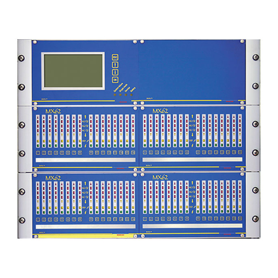
Example of a front side with LCD pannel And keyboard for 64 detectors A del(s) module is dedicated to channels. A pannel with keyboard gets 2 DEL(s) modules The channels are numbered from 1 to 16. The pannel with keys are extensibled and are numbered from A to D 3. - Page 21 LEDs for Channel Information: Excess of Measuring Range Alarm 3 Alarm 2 Alarm 1 Insufficient Signal Fault (Channel Malfunction) Power (Operation) Key Button The four LEDs on the logo module or optional LCD module serve for system monitoring. LEDs for System Information: These blinking LEDs indicate a certain system status.
-
Page 22: Connecting Status
3.2. Connecting Status Upon switch-on or directly after voltage cutoff, alarms are suppressed for 1 to 10 minutes, depending on the type of transducer (setting via software Config- Pro). Ü Ü As many transducers signal undefined values after switch-on, this mode eliminates any false alarms. -
Page 23: Insufficient Signal
3.3.3. Insufficient Signal The measuring signal has, for example, drifted below 3.2mA. Measuring is still given though the transducer should be calibrated. This signal is not latching. 3.3.4. Alarms The system WinPro® has three freely adjustable alarm levels within the measur- ing range of 4-20mA. -
Page 24: Maintenance Mode
Resetting is via the key buttons for the respective channels. In case an LCD module is used, pressing the key button the first • time is for the LCD display. Pressing the key button a second time resets an existing relay for •... -
Page 25: Forcing Of The Alarm Relays Into "Out Of Alarm" Position
Channel Selection: After positioning of the rotary switch, one or several channels in succession can be selected for a function by pressing the respective key button (for more than two seconds). After the two seconds have elapsed, all LEDs for the relevant channel briefly light up. -
Page 26: Operational Test
3.4.2. Operational Test Switch Position 2 The operational test is indicated by blinking of the LED for ‘fault’, the relays are activated whatever the type of (positive/negative) security chosen. All other LEDs for the channel and the allocated relays are activated. The analog output signal is set to 2mA. -
Page 27: Pc Communication
3.4.5. PC Communication Switch Position 5 PC communication allows configuration of the system WinPro® by means of the software ConfigPro. 3.5. Single Mode The single mode is indicated by blinking of the yellow LED for ‘single mode’. During this status, redundancy or comparison of the two controllers with each other is disturbed. -
Page 28: Measures Against Faults
3.7. Measures against Faults Display: Possible Cause: Measures against Faults: LED for ‘fault’ Line disconnection Measure signal current Insulation defect Check connection Defective transducer Check gas concentration sepa- Wrongly connected line rately A transducer has exceeded Exchange transducer 24.5mA. (Attention! Danger!) Part of the LEDs for An analog input module is de- Check connection between ana-... -
Page 29: Operating Of Lcd Module
4. Operating of LCD Module The optional LCD module (240 x 128 pixels) is operated via its four key buttons as well as those for channel information. Besides display of the individual chan- nels indicating information on measuring points and system events, menu-driven operation allows calling up of settings and information plus controlling of the data logger and printer. -
Page 30: Menu
4.2. Menu The menu is entered by operating the key buttons for “OK” or “ESC” and automatically left 60 seconds after the last operation or via the key button for “ESC”. The following information can be obtained: • System • Channel information •... -
Page 31: Maintenance
5. Maintenance Maintenance of gas detection systems includes inspection, servicing, calibration and adjustment. Inspection and servicing by specialists comprise verification of key buttons, LEDs and relay contacts, operational check of alarm thresholds with test gas to ensure correct triggering of alarms, checking of the LCD display as well as cali- bration and adjustment of transducers. -
Page 32: Automatic Calibration Of Transducer Tbgw Ex
! ! Attention ! ! Since the 4-20mA are altered, the signal of 4-20mA is to be restored in case the transducer is changed or directly calibrated. This is achieved via the function for calibration of the maintenance mode. 5.1.3. Automatic Calibration of Transducer TBGW EX The transducer TBGW EX has an analog as well as an RS 485 con- nection to the system WinPro®. -
Page 33: Technical Data
6. Technical Data Mains Supply: 230V AC, 50Hz or 24V DC Power Consumption: Power consumption is determined by the num- ber of modules and current requirement of transducers. Maximum Input: 64 transducers (8 analog input modules with 8 inputs each) Input Signal: standardized 4-20 mA with a load of 200 ohms (3-wire and 2-wire technique) as well as RS... -
Page 34: Terminal Connections, Jumpers And Rotary Switch
Operation: one key button per channel as well as four key buttons for the optional LCD module Temperature Range: 0 °C to + 55 °C Storage Temperature: - 25 °C to + 60 °C Relative Humidity: 5 % to 90 % Pressure: 80 kPa to 120 kPa Installation:... - Page 35 Status Status Rotary Switch Display of µC B µC A Reset Reset for Servicing Rotary Switch µC B µC A Analog Input Modules EPS Signal or +24 V Display Output Module +24V Service Single M. Controller Module with basic PCB and additional Error plugged PCB...
-
Page 36: Analog Input Module (Aem)
7.2. Analog Input Module (AEM) Different addresses between 1 and 8 are to be allocated to the analog input mod- ules with the aid of the fitted rotary switch. Five terminals each are available for all eight input channels: • 24 V Input requirement of the transducer •... -
Page 37: Basic Relay Module (Rbm) And Extension Relay Module (Rem)
7.3. Basic Relay Module (RBM) and Extension Relay Module (REM) Different addresses between 1 and 8 are to be allocated to the relay modules with the aid of the fitted rotary switch. The extension relay module with relays 9 to 16 is plugged onto the basic relay module with relays 1 to 8. -
Page 38: Analog Output Module (Aam)
7.4. Analog Output Module (AAM) Different addresses between 1 and 8 are to be allocated to the analog output modules with the aid of the fitted rotary switch. Each relay has a pertaining jumper via which 0-10V or 4-20mA can be se- lected. -
Page 39: Lcd Module
Module Contrôleur ( CM ) - long. Max 2 m Module Sorties Analogiques ( AAM ) - long. Max 0,5 m Module Relais ( RM ) - long. Max 0,5 m Sélecteur Cavalier Fin de Bus rotatif Limande ( 16 fils ) Adresses de Gauche FIN DE BUS... -
Page 40: Led Module
7.6. LED Module The LED panels are supplied with electronic modules fixed on the back of the LED front plate. An electronic module supplies 8 measurement channels. CANAUX 9 à 16 CANAUX 1 à 8 ( LEDM ) ß ß ( LEDM ) 3.2 ( CM ) 1.1 ß... -
Page 41: Loop-Module Loopm
As does the standard LCD module, le LCD copy module indicates the system status of the WinPro® by means of four LED. If the LCD copy module is the last module to be operated on the display bus, the bus will have to be terminated on the LCD copy module with the help of bus end jumper J1 (see drawing of LCD module). -
Page 42: Connection And Installation
8. Connection and Installation 8.1. Wiring 8.1.1. Mains Supply ® The electric installation for the WinPro has to provide an isolator (eg an overload release) to guarantee a secure disconnection from the ® mains supply. The WinPro must not be installed in hazardous areas. ®... - Page 43 EXAMPLES OF CONNECTING Ø 24Vcc CAPTEURS LEL et/ou O2 Avec utilisation du RS485 R BOUCLE < 17 Rs485 24Vcc O2 experimental cavern R BOUCLE < 7 R BOUCLE < 50 Boite de jonction...
- Page 44 LEL experimental cavern R BOUCLE < 16 Boite de R BOUCLE < 16 jonction 24Vcc Boite de jonction R BOUCLE < 7 24Vcc CAPTEURS OLCT IR (GD10) R BOUCLE < 10 VERIFIER BORNES...
- Page 45 24Vcc O2 SERVOMEX (liaisons électriques) R BOUCLE < 16 VERIFIER BORNES 24Vcc Boîtier BRIS DE GLACE Non adressable Rt BOUCLE FILAIRE < 32 3.9K...
- Page 46 Safeye type 204 (liaisons électriques) R BOUCLE < 16 VERIFIER BORNES 24Vcc R BOUCLE < 14 80m. R BOUCLE < 14 VERIFIER BORNES...
- Page 47 R BOUCLEs à calculer selon architecture < ?? 24Vcc CAPTEURS 4/20mA LEL et/ou O2 Câblage en variante 1 TGBW TGBW TGBW RS485 pour étalonnage RS485 RS485 RS485 1,2,3…...
- Page 48 24Vcc 24Vcc CAPTEURS 4/20mA LEL et/ou O2 Câblage en variante 2 - module ANA. déporté TGBW TGBW RS485 RS485 1,2,3… … R BOUCLE à calculer selon architecture < ?? RACCORDEMENT DU MODULE ADAPTATEUR A WinPro 24Vcc 24Vcc 24Vcc CABLES POUR RESEAU RS485 Options d’alimentation quand A pas B...
- Page 49 CAPTEURS numériques adressables LEL et/ou O2 Montage en boucle Capteur TGBW TGBW TGBW 24Vcc RS485 RS485 RS485 RS485 1,2,3… R BOUCLE à calculer selon architecture < ?? RS485 1,2,3… CABLE POUR RESEAU RS485...
- Page 50 BRIS DE GLACE adressables Montage en boucle adresse adresse adresse TGBW TGBW TGBW 24Vcc RS485 RS485 RS485 RS485 1,2,3… R BOUCLE à calculer selon architecture < ?? RS485 1,2,3… CABLE POUR RESEAU RS485...
- Page 51 24Vcc Adresses Device x Device y Device z Montage en boucle 4/20mA 3fils 4/20mA 2fils 4/20mA 2fils adresse adresse adresse TGBW TGBW TGBW 24Vcc RS485 RS485 RS485 RS485 1,2,3… R BOUCLE à calculer selon architecture < ?? RS485 1,2,3… CABLE POUR RESEAU RS485...
-
Page 52: Installation Of The Winpro
8.2. Installation of the WinPro® ! ! Attention ! ! Make sure power supply is cut off prior to opening the unit. 8.2.1. Wall-mounted Housing The size of the wall-mounted housing depends on the number of modules. Attention is to be paid to free accessibility. Safety systems should always be installed at a distance from any devices with high generic emission. -
Page 53: Accessories
9. Accessories Optional Accessories: Order No. Software COM62 for parameterization of the Win- 6 312 395 Pro ® Alarm Supervision software 10. Approvals 10.1. CE Marking EMC Directive 89/336/EWG: The unit has passed EMC testing according to EN 50081-1 and EN 50270 and can be employed in domestic and industrial areas in view of generic emission and immunity. -
Page 55: Logicom 62 Software
11. LOGICOM 62 SOFTWARE After having started COM 62, the user has to enter his Usernames. This name will be stored with every relevant action, i.e. storing a configuration into a file or uploading a configuration in the controller module. Furthermore the administrator of the system can set different rights for every user;... - Page 56 Permits to select : - automatically 1 , - manually 2 . 1 Selection of ComPort/automatic detection During Startup COM62 checks all available COM ports for a WinPro Controller Module. If a WinPro has been found, an acoustic ok-signal is given and the transmission menu is enabled;...
- Page 57 Permits to choose the language which will be used into the software.
- Page 58 The screen displays the different possibilities of the COM62 software.
- Page 59 Examples of programmed possibilities.
- Page 60 To indicate the different parameters related to an established installation : Use the available menus into the window 1 .
- Page 61 8 x 4..20mA + RS485 8 x 4..20mA + RS485 Permits to configure : - the imput modules, - the relay modules, - the analog modules. The first important step is the configuration of the I/O modules. I/O modules are divided in the groups of Input modules, Relay modules and Analog Output modules.
- Page 62 Permits to configure the main characteristics of an established installation. - The inhibition time at the imput, - The authorized time for an adjustment - Cadence of the preventive maintenance etc…...
- Page 63 8 x 4..20mA + RS485 8 x 4..20mA + RS485 Initial Calibration Re-Calibration 16 existing channels þ description 1 þ description 2 þ description 3 þ description 4 þ description 5 þ description 6 þ description 7 mismatched mismatched mismatched mismatched mismatched mismatched...
- Page 64 - Configuration up to the inputs (measurement channel type)
-
Page 65: Detector Settings
8 x 4..20mA + RS485 8 x 4..20mA + RS485 Initial Calibration Re-Calibration LCD display LED display Profile channel 2-3 [No.11] B,1,2 Normal mode Rack A-11 16 existing channels 85120-667512 Beschreibung1 Beschreibung2 TCOD-IR5 Beschreibung3 TCOD-IR5 Beschreibung4 TCOD-IR5 Methan TBGW-EX Beschreibung5 TCOD-IR5 Beschreibung6 TCOD-IR5... - Page 66 - configuration of detector's caracteristics.
- Page 67 - Test / calibrating up to a detector.
- Page 68 Permits to analyse for a defined detector the zero and sensitivity derives...
- Page 69 LED PANEL CONFIGURATION 13 16 Beschreibung 10 Beschreibung 1 LC 2-2 Beschreibung 12 Beschreibung 2 LC 2-4 Beschreibung 3 LC 2-7 Beschreibung 15 Beschreibung 4 Beschreibung 5 Beschreibung 6 Beschreibung 7 Beschreibung 8 Beschreibung 9 Beschreibung 11 Beschreibung 2 Beschreibung 13 Beschreibung 16 Permits to configure a LED module.
- Page 70 ALARM SETTINGS 8 x 4..20mA + RS485 8 x 4..20mA + RS485 Beschreibung1 Beschreibung2 Beschreibung3 Beschreibung4 100% disabled Beschreibung5 Beschreibung6 Beschreibung7 Beschreibung8 Beschreibung9 Beschreibung10 2-2 Beschreibung11 2-3 Beschreibung12 2-4 Beschreibung13 2-5 Beschreibung14 2-6 Beschreibung15 2-7 TBGW -EX 60.0 % LEL Beschreibung16 2-8 A-11 Normal mode...
-
Page 71: Configuration Of Relays
Alarm1 HF DPL015 user defined SIRENE/FLASH HF COULOIR Alarm1 AMB HF DPL015/014 user defined SIRENE/FLASH HF LOCAL PLASMA Alarm1 COMB HF DPL015 user defined SIRENE/FLASH HF COMBLES PLASMA Alarm1 HF DPL014 user defined Alarm1 HF DPL013 user defined SIRENE/FLASH H2 LOCAL PLASMA Alarm1 AMB HF DPL013/011 user defined... - Page 72 Then the logical function which shall be used has to be selected: • • • VOTING The basic configuration of a relay is done by selecting the events on the left side and pushing them (by drag and drop) on a relay on the right side. Relays which shall not be used have to marked as "Rejected".
- Page 73 This window gives an overview about the existing configuration an allows to change the fol- lowing properties of a relay: Buzzer Relay y/n Description (click on the field) Add Events to the existing configuration Delete Events from the existing configuration The timing for the relays is only displayed in this window and has to be configured under [Relays ->...
-
Page 74: Configuration Of Analog Outputs
Description Profile Group: lowest actual Beschreibung1 Group: lowest actual Beschreibung2 Beschreibung3 Group: lowest actual Beschreibung4 Group: lowest actual Beschreibung5 Group: lowest actual Beschreibung6 Group: lowest actual Beschreibung7 Group: lowest actual Beschreibung8 Beschreibung9 Group: lowes t actual Beschreibung10 Beschreibung11 Beschreibung12 Beschreibung13 Beschreibung14 Beschreibung15 Beschreibung16... - Page 75 Putting into memory of some used parameters (type, connection of 4/20mA in accordance with values…)
- Page 76 - Choice of the detected gas into a list putted into memory : window 1 , - Automatic display of the gas characteristics 2 , - This window 3 allows to programme another gas which is not avail- able into the present list.
- Page 77 Allows to choose a type of pre-programmed detector...
- Page 78 Allows to define a detection profile...
- Page 79 Profile (continuation) : type of alarm...
- Page 80 Type of alarm (continuation)
- Page 81 Type of alarm (continuation)
-
Page 83: Upload / Download
If the configuration has passed all plausibility checks, it may be uploadd in the controller module by selecting the menu item [Transmission->Upload] in the main menu. This menu is only enabled if a COM62 Controller module has been connected to a serial interface of the PC.
Need help?
Do you have a question about the MX62 and is the answer not in the manual?
Questions and answers