Table of Contents
Advertisement
Quick Links
Advertisement
Table of Contents

Related Manuals for Labomed CxL


Summary of Contents for Labomed CxL
- Page 1 C x L Laboratory Microscopy User Manual To ensure proper use of this instrument as well as to avoid injury while operating Part No: 9135000-795 Instrument, understanding this manual completely before use is highly recommended. Issue 1.5 Printed on June,2020...
-
Page 3: Table Of Contents
1. INTRODUCTION 2. SAFETY INFORMATION GETTING STARTED MAINTENANCE & STORAGE CAUTION CARE & MAINTENANCE CLEANING & DISINFECTION 3. CxL MONOCULAR 4. CxL BINOCULAR 5. CxL TRINOCULAR 6. UNPACKING YOUR MICROSCOPE 7. STANDARD COMPONENTS 8. OPTIONAL ACCESSORIES 11-12 9. INITIAL SETUP 10. -
Page 4: Introduction
INTRODUCTION The CxL is a laboratory microscope reflecting a modern design as well as the latest in optical and mechani- cal advancements. Designed for professionals as well as students, this microscope offers many features and functions for a diverse set of applications. -
Page 5: Safety Information
Do not place microscope on a flexible surface, as this could result in blocking the air vents and cause overheating. 4. Always use the power cord provided by LABOMED. If the proper power cord is not used, product safety performance cannot be warranted. -
Page 6: Getting Started
[Warning against risk of electric shock] [Warning against damage in non- compliance with instructions manual] If the warning label is stained or peeled off, contact your LABOMED distributor. GETTING STARTED 1. A microscope is a precision instrument with delicate glass compo- nents. -
Page 7: Caution
CAUTION If the microscope is used in a manner not specified by this manual, the safety of the user may not be warranted. In addition, the equipment may also suffer damage. Always use the equipment as outlined in this instruction manual. CARE &... -
Page 8: Cleaning & Disinfection
Caution: Do not use aggressive organic solvent such as acetone for cleaning painted surfaces and plastic parts of the microscope. 3. Never attempt to dismantle : Never attempt to dismantle the instrument so as to avoid the possibility of impairing its operational efficiency and accuracy. -
Page 9: Cxl Monocular
CxL MONOCULAR Monocular viewing tube Revolving nose piece Objectives Mechanical stage Abbe condenser Coarse and fine focus knob Light regulator X-Y movement control knob Issue 1.5 9135000-795 Printed on June,2020... -
Page 10: Cxl Binocular
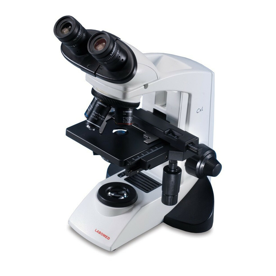
CxL BINOCULAR Focusable eyepieces Binocular viewing tube Revolving nose piece Objectives Mechanical stage Abbe condenser Coarse and fine focus knob Light regulator X-Y movement control knob 9135000-795 Issue 1.5 Printed on June,2020... -
Page 11: Cxl Trinocular
CxL TRINOCULAR Port for camera adapter Focusable eyepieces Trinocular viewing tube Revolving nose piece Objectives Mechanical stage Abbe condenser Coarse and fine focus knob Light regulator X-Y movement control knob 9135000-795 Issue 1.5 Printed on June,2020... -
Page 12: Unpacking Your Microscope
UNPACKING YOUR MICROSCOPE Mirror attachment (if ordered) Eyepieces Power Cord Camera (if ordered) Observation tube Software CD (if ordered) Microscope Arm Issue 1.5 9135000-795 Printed on June,2020... -
Page 13: Standard Components
STANDARD COMPONENTS • After removing your microscope from its packaging, make sure that all of the following contents are present. • The differences in configurations are the number of objectives, type of observation head, type of illumi- nation and purchased optional accessories. •... -
Page 14: Optional Accessories
OPTIONAL ACCESSORIES SYSTEM DIAGRAM OF OPTIONAL ACCESSORIES ATLAS CMOS CAMERA TOUCH SCREEN C-MOUNT ATLAS C-MOUNT TOUCH SCREEN MONOCULAR BINOCULAR TRINOCULAR WF 10x WF 16x WF 20x LP 4x LP 20x LP 40x LP 100x LP 100x IRIS LP 10x PHASE LP 40x PHASE LP 10x LP 60x... - Page 15 REFLECTION MIRROR The reflection mirror is designed to be used in out door observation settings wherein a power source is not readily available. The mirror attachment makes it possible to use natural light to illuminate your specimen. The microscope should be installed in any place that is not exposed to direct sunlight.
-
Page 16: Initial Setup
INITIAL SETUP OBJECTIVES Objectives are factory set. Objectives are par-centered and parfo- calised during assembly. All objectives have been secured for a tight fit to prevent them from coming loose during transit. To remove an objective, rotate it counterclockwise while holding it with a rubber grip to avoid any slippage. -
Page 17: Replacement Of Critical Components
Applicable bulb: 6V20W Halogen bulb P/N CX-013 Always use the designated bulb. Using a bulb other than those specified by LABOMED may lead to a fore hazard or and low illumination. Fingerprints or stains on the lamp bulb reduce its life. If contamination occurs, wipe bulb surface with a cloth slightly moistened with alcohol. - Page 18 3. Detach connector of connecting wires (shown as 4) 4. Remove two screws (shown as 6) provided on battery clamp with Cross head screw driver. 5. Replace existing Battery with new battery from LABOMED (Refer part no. below) 6. Reverse steps 5 to 1, to complete the process.
-
Page 19: Summary Of Bright Field Observation Procedure
SUMMARY OF BRIGHT FIELD OBSERVATION PROCEDURE Flip the main switch to “ON” Place the specimen on the stage. Main switch Fuse Holder Engage the 10X objective in the light path. Bring the specimen in focus. Adjust the observation tube and eyepieces Adjust the interpupillary distance. -
Page 20: Detailed Observation Procedure
DETAILED OBSERVATION PROCEDURE TURNING THE LAMP ON 1. Flip the main switch to “I” (ON) as shown in figure 15. Fig. 15 2. Rotating the light intensity adjustment knob (Fig. 16) in the direction of the arrow increases brightness and rotating knob in the opposite direction decreases brightness. - Page 21 Cover glass Cover glass This is the glass plate paced on the specimen. For optimum optical performance, the cover glass thickness, which is the distance from its surface to the specimen surface, should be 0.17mm. Slide glass Slide glass This glass plate should ideally have a length of 76mm, width of Fig.
- Page 22 ADJUSTING THE INERPUPILLARY DISTANCE (IPD) The inter-pupillary distance adjustment consists of regulating the two eyepieces to align with both eyes’ pupils so that you can observe a single microscope image through two eyepieces in stereo vision. This greatly helps to reduce fatigue and discomfort during observation.
- Page 23 ADJUSTING THE CONDENSER POSITION AND APERTURE IRIS DIAPHRAGM The condenser is most often used in the highest position. If the observed field of view is not bright enough, brightness may be improved by lowering the condenser slightly. Rotate the condenser height adjustment knob (1) in clockwise direction to move the condenser to the highest or desired position.
- Page 24 USING THE 100X IMMERSION OBJECTIVE The designated immersion oil should be in contact with the cover lens of the 100X immersion objective. If not, the specimen will appear distorted and dull. It is recommended that LABOMED immersion oil is always used. Immersion Process 1.
-
Page 25: Troubleshooting Guide
Under certain conditions, performance of the unit may be adversely affected by factors other than defects. If problems occur, please review the following list and take corrective action as needed. If problem persists, please contact LABOMED or your local LABOMED dealer. OBSERVATION... - Page 26 OBSERVATION CAUSE REMEDY Set the specimen correctly with the The specimen slide is upside down 8. Objective hits the specimen when cover glass facing upwards an objective is switched to a higher magnification objective The cover glass is too thick Use a cover glass with thickness of 0.17mm The stage is raised too high...
-
Page 27: Specifications
SPECIFICATIONS 1. Illumination Built-in illumination system Halogen/ LED 2. Focusing mechanism Stage height adjustment mechanism Fine adjustment scale: 3.0µm per graduation Fine adjustment stroke: 0.2mm per turn Total stroke: 12.7mm Co-axial coarse and fine focusing on ball drive 3. Revolving nose piece Quadruple positions fixed (Reverse angle) 4. - Page 28 920 Auburn Court Fremont, CA 94538 U.S.A. Phone: 510-445-1257 Fax: 510-991-9862 E-mail: sales@laboamerica.com www.laboamerica.com EU REP. Labomed Europe Essebaan 50 NL-2908 LK Capelle a/d IJssel The Netherlands Tel: +31 (0)10 4584222 Fax: +31 (0)10 4508251 E-mail: info@labomedeurope.com A28240 ISO9001 LABOMED...
Need help?
Do you have a question about the CxL and is the answer not in the manual?
Questions and answers