Table of Contents
Advertisement
Quick Links
Advertisement
Table of Contents

Related Manuals for Bosch Worcester Greenstar Comfort II RF


Summary of Contents for Bosch Worcester Greenstar Comfort II RF
- Page 1 Installation and operating instructions Radio Frequency Twin Channel Programmable Room Thermostat and Receiver Greenstar Comfort II RF For EMS compatible Worcester Greenstar condensing boilers se le ct se le ct ad va nc e m en u ad va nc e 6720810965-00.1Wo UK/IE...
-
Page 2: Table Of Contents
Contents Contents Key to symbols and safety instructions ... 3 Fault finding and resolution ....16 1.1 Key to symbols . -
Page 3: Key To Symbols And Safety Instructions
Key to symbols and safety instructions Key to symbols and safety instructions Key to symbols General safety instructions These installation instructions are intended for heating Warnings engineers, and electricians. Warnings in this document are identified by a ▶ Read any installation instructions (boiler, heating controls, etc.) carefully before starting the installation. -
Page 4: Comfort Ii Rf
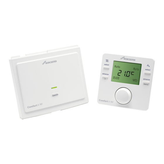
Comfort II RF Comfort II RF The Comfort II RF comprises a wall mounted twin channel RF programmable room thermostat and a boiler or wall mounted RF receiver. Programmable room thermostat The wall mounted unit is a twin channel RF Programmable room thermostat. The Programmable room thermostat is for central heating and hot water control with modulating/enhanced load compensating boiler regulation. -
Page 5: Receiver
Comfort II RF installation Receiver ▶ Set time and date on the Programmable room thermostat ▶ The units will automatically connect to each other This unit is only used in conjunction with the Programmable room thermostat. ▶ Ensure that the signal strength is adequate at the The unit can be mounted in the boiler fascia, refer to your boiler Programmable room thermostat before mounting in a Installation, Commissioning and Servicing instruction manual... -
Page 6: Programmable Room Thermostat Mounting
Comfort II RF installation Optional wall mounting kit The Comfort II RF connects to your boiler’s EMS BUS connections only, on an edge connector identified either with B B or Using the wall plate as a template, mark the position of the mounting screws. - Page 7 Comfort II RF installation Room Thermostat positioning The thermostat requires free air flow and should be mounted in an open area and not obscured by curtains or furniture. The Before mounting the room Programmable room thermostat on thermostat should be mounted no closer than 300mm to metal the wall, it is good practice to find a position that affords good objects, including metal wall boxes.
-
Page 8: Date And Time Set Up
Operation Date and time set up Low RF signal strength The A21 fault code indicates no RF signal, refer to section 5.2 A21 will be displayed at initial switch on until Installer/Radio settings and section 6.2 Pairing/ the two units have established an RF Unpairing. -
Page 9: Room Temperature Indication In Auto Mode
Operation 1. Current room temperature 4.2.3 Room temperature indication in the Off mode 2. HW operational status When the Programmable room thermostat is in the Off mode, pressing the knob once and releasing will display 3. Current day “Permanently”and the temperature of 5 °C. 4. -
Page 10: Programmable Room Thermostat Settings
Programmable room thermostat settings Press the Return button at any time to return to the Programmable room thermostat settings previous higher level. In the Time program you can set up to 6 time and temperature There are two levels of settings: periods for CH. -
Page 11: Hw (Hot Water)
Programmable room thermostat settings ▶ Repeat the process to set the hours and minutes for Time ▶ Press the knob to select the first DHW ON setting setting 4 ▶ The hours flash ▶ Temp. setting 4 flashes, this will be the temperature that is ▶... -
Page 12: Info
Programmable room thermostat settings When the Holiday function is set, via this program, the function 2. Time/Date will become active at midnight of the day set and inactive at This function allows the current time and date to be set, this midnight on the last day set. -
Page 13: Installer
Programmable room thermostat settings Time format The Programmable room thermostat will be reset to factory default settings, as shown in the table below, any customised ▶ Turn the knob to select Time format times for heating or hot water will have to be re-entered. ▶... -
Page 14: System Data
Installer menu are reset back to default settings, four dashes progress across the display until the reset has taken Landlords: place, ▶ Call the Worcester Bosch technical support if NO is chosen, no reset takes place team for instructions of how to set the 5.2.3 Heat circuit... -
Page 15: System Info
Receiver 5.2.5 System info Pairing/Unpairing 1. Turn the knob to select System info The Programmable room thermostat and 2. Press the knob and Install date is displayed Receiver are delivered together and are 3. Press the knob and the install date is displayed factory paired, they will automatically 4. -
Page 16: Fault Finding And Resolution
Fault finding and resolution Fault finding and resolution If a fault code is displayed the user must first press the knob to return to the main display. The last 5 control faults can be viewed in the Faults history (refer to 5.2.4 Maintenance). If a fault appears that is not listed within the table it could be that a boiler fault has occurred. -
Page 17: Unit Replacement - Single Zone Heating, Or Multi-Zone Heating Utilising A Greenstar Wiring Centre
Fault finding and resolution Fault code Problem Description Resolution Multiple pairing fault Displayed when no zone is available for Unpair units and pair back up using a different this room thermostat zone setting for each room thermostat. Up to 3 zones can be set up. -
Page 18: Servicing
Servicing Servicing These units can not be serviced. Should either unit fail to function correctly check that the: ▶ Programmable room thermostat settings are correct ▶ RF signal link between the units is set up correctly, sections 6.2 and page 15 Radio settings ▶... -
Page 19: Erp Class
Environment / disposal Environmental protection is a fundamental corporate strategy of the Bosch Group. The quality of our products, their economy and environmental safety are all of equal importance to us and all environmental protection legislation and regulations are strictly observed. - Page 20 TRAINING: 0330 123 0166 SALES: 0330 123 9669 Worcester, Bosch Group Cotswold Way, Warndon, Worcester WR4 9SW. Tel. 0330 123 9559 Worcester, Bosch Group is a brand name of Bosch Thermotechnology Ltd. worcester-bosch.co.uk *2703726_REV1* Comfort II 6 720 810965 (2017/02)
Need help?
Do you have a question about the Worcester Greenstar Comfort II RF and is the answer not in the manual?
Questions and answers