Table of Contents
Advertisement
Quick Links
Advertisement
Table of Contents

Related Manuals for Bosch WORCESTER Greenstar Comfort I RF


Summary of Contents for Bosch WORCESTER Greenstar Comfort I RF
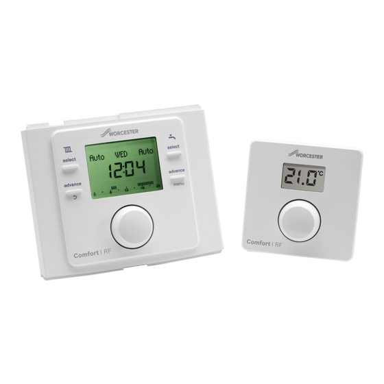
- Page 1 Installation and operating instructions Radio Frequency Twin Channel Programmer/Receiver and Room Thermostat Greenstar Comfort I RF For EMS compatible Worcester Greenstar condensing boilers se le ct se le ct a d va n ce m e n u a d va n ce 6720810964-00.1Wo UK/IE...
-
Page 2: Table Of Contents
Contents Contents Key to symbols and safety instructions ... 3 Servicing ........18 1.1 Key to symbols . -
Page 3: Key To Symbols And Safety Instructions
Key to symbols and safety instructions General safety instructions Key to symbols and safety instructions These installation instructions are intended for heating engineers, and electricians. Key to symbols ▶ Read any installation instructions (boiler, heating controls, Warnings etc.) carefully before starting the installation. ▶... -
Page 4: Comfort I Rf
Comfort I RF Comfort I RF The Comfort I RF comprises a boiler or wall mounted twin channel Programmer/Receiver and wall mounted Room thermostat. Programmer/Receiver The boiler fascia mounted unit is a twin channel Programmer/Receiver and is connected to an RF Room thermostat transmitter. The Programmer/Receiver is for central heating and hot water control with modulating/enhanced load compensating boiler regulation. -
Page 5: Rf Room Thermostat
Installation RF Room thermostat Installation The Room thermostat can only be used in conjunction with the Programmer/Receiver. The Room thermostat displays the CAUTION: Mains supplies current room temperature and is also used to set a new ▶ Isolate the mains supplies to the boiler temperature set point. - Page 6 Installation Programmer/boiler connection NOTICE: EMS Connections ▶ The Programmer must NOT be connected to the boiler’s 230 volt supply or an external 230 volt supply. ▶ Ensure that the EMS cable is at least 100mm away from any power cables to eliminate any mains interference ▶...
-
Page 7: Room Thermostat Mounting
Installation Room thermostat mounting ▶ Turn the knob to select S 2 Before mounting the Room thermostat wall plate, fit batteries in the Room thermostat unit and turn the boiler on to identify a location that offers good RF signal. Fitting the batteries Ensure that the batteries are correctly oriented ▶... -
Page 8: Time And Date Set Up
Installation Wall mounting plate Time and date set up To remove the wall mounting plate: A21 will be displayed at initial switch on until 1. Insert a suitable flat bladed screwdriver into the slot on the the two units have established an RF bottom edge of the thermostat communication link 2. -
Page 9: Operation
Operation 1. Central heating operational status Operation 2. Current day 3. HW operational status The Programmer/Receiver is supplied with factory set default 4. Current time ON and OFF times, for central heating (CH) and hot water 5. Graphical indication of the current time program (HW), that are shown in the table below. -
Page 10: Programmer/Receiver Settings
Programmer/Receiver settings Time program Programmer/Receiver settings Select Time program with the knob, and press to enter. Press the Return button at any time to return to the There are two levels of settings: previous higher level. 1. User In the Time program you can select ON and OFF times for the 2. -
Page 11: Hot Water
Programmer/Receiver settings 5.1.2 Hot water To cancel the holiday function: This Time program is used to set your required ON and OFF ▶ Press the menu key for more than three seconds to enter times for the hot water. The Programmer has default time user menus and select Holiday, ON will be displayed. -
Page 12: Installer
Programmer/Receiver settings ▶ Turn the knob to select ON or OFF, if ON is selected the Installer Programmer will automatically adjust the time in These functions are only used by the installer/service engineer conjunction with daylight savings time and are useful during installation. ▶... -
Page 13: Reset All
The tenant should call this number to arrange a convenient date for the service. Normal operation Landlords, call the Worcester Bosch technical support team for Under normal operation the display shows the current room instructions of how to reset the Maintenance message or temperature in centigrade. -
Page 14: Settings
Room thermostat Low RF signal strength The A21 fault code will be displayed at initial switch on until the two units have established an RF communication link A continuous A21 fault code indicates no RF signal, refer to section 6.7 for the signal strength indication on the Room Thermostat. -
Page 15: E 1 Room Temperature Sensor Adjustment
Room thermostat E 1 Room temperature sensor adjustment rF 1 Pair with other devices If it is suspected that the temperature display is off by a few The Programmer/Receiver and Room degrees and if there is a precision temperature gauge/meter thermostat are delivered together and are available, the display can be offset by ±... -
Page 16: Fault Finding And Resolution
Fault finding and resolution Fault finding and resolution If a fault code is displayed the user must first press the knob to return to the main display. The last 5 control faults can be viewed in the Faults history (refer to 5.2.2 Maintenance). Fault table Fault code... -
Page 17: Unit Replacement
Fault finding and resolution Unit replacement IMPORTANT ▶ When replacing one unit, unpair the unit from the associated Receiver or Room thermostat, before pairing the new unit ▶ Only one Room thermostat can be connected to the Receiver 7.2.1 Unpair 7.2.2 Pair Set the Programmer/Receiver to the unpairing mode: Set the Programmer/Receiver to the pairing mode:... -
Page 18: Servicing
Servicing Servicing These units can not be serviced. Should either unit fail to function correctly check that the: ▶ Programmer/Receiver settings are correct ▶ RF signal link between the units is set up correctly, sections 6.5 and page 13 Radio settings ▶... -
Page 19: Erp Class
The data represented in the table below is required for the Environmental protection is a fundamental corporate strategy completion of Energy Related Product (ErP) Directive System of the Bosch Group. Package fiche and, subsequently, the ErP system data label. The quality of our products, their economy and environmental... - Page 20 0330 123 9119 TRAINING: 0330 123 0166 SALES: 0330 123 9669 Worcester, Bosch Group Cotswold Way, Warndon, Worcester WR4 9SW. Tel. 0330 123 9559 Worcester, Bosch Group is a brand name of Bosch Thermotechnology Ltd. worcester-bosch.co.uk *2703724_rev1* 6 720 810 964 (2017/02)
Need help?
Do you have a question about the WORCESTER Greenstar Comfort I RF and is the answer not in the manual?
Questions and answers