Table of Contents
Advertisement
Harbor Breeze® is a registered trademark
of LF, LLC. All Rights Reserved.
ATTACH YOUR RECEIPT HERE
Purchase Date _________________________
Questions, problems, missing parts? Before returning to your retailer, call our customer
service department at 1-800-643-0067, 8 a.m. - 6 p.m., EST, Monday - Thursday, 8 a.m. - 5 p.m.,
EST, Friday.
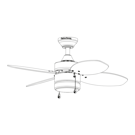
ITEM #0806201, 0806202, 0806203
RIVERVIEW CEILING FAN
1
MODEL #40661, 40662, 40663
Lowes.com/harborbreeze
Advertisement
Table of Contents

Related Manuals for Harbor Breeze 40662


Summary of Contents for Harbor Breeze 40662
- Page 1 ITEM #0806201, 0806202, 0806203 RIVERVIEW CEILING FAN MODEL #40661, 40662, 40663 Harbor Breeze® is a registered trademark of LF, LLC. All Rights Reserved. ATTACH YOUR RECEIPT HERE Purchase Date _________________________ Questions, problems, missing parts? Before returning to your retailer, call our customer service department at 1-800-643-0067, 8 a.m.
-
Page 2: Table Of Contents
TABLE OF CONTENTS Package Contents . . . . . . . . . . . . . . . . . . . . . . . . . . . . . . . . . . . . . . . . . . . . . . . . . . . . . . . . . . . . . . . . . 3 Hardware Contents . -
Page 3: Package Contents
PACKAGE CONTENTS PART DESCRIPTION QUANTITY Downrod Downrod Pin (preassembled to the Downrod [A]) Downrod Clip (preassembled to the Downrod [A]) Mounting Bracket Canopy Canopy Cover Motor Assembly Light Kit (preassembled to the Motor Assembly [G]) Yoke Cover Bulb Glass Bowl Blade Arm Blade Motor Screw (preassembled to the Motor Assembly [G]) -
Page 4: Hardware Contents
(shown actual size) HARDWARE CONTENTS Wire Connector Blade Screw Blade Washer Screw Cap Pull Chain Extension Qty . 3 Qty . 12 Qty . 12 Qty . 12 Qty . 2 + 1 extra + 1 extra + 1 extra + 1 extra Secondary Support... -
Page 5: Safety Information
SAFETY INFORMATION Please read and understand this entire manual before attempting to assemble, operate or install the product . • Before you begin installing the fan, disconnect the power by removing fuses or turning off the circuit breakers . • Make sure all electrical connections comply with local codes, ordinances, the National Electrical Code and ANSI/NFPA 70-199. Hire a qualified electrician or consult a do-it-yourself wiring handbook if you are unfamiliar with installing electrical wiring . • Make sure the installation site you choose allows a minimum clearance of 7 ft . -
Page 6: Preparation
SAFETY INFORMATION CAUTION: Be sure the outlet box is properly grounded or that a ground (green or bare) wire is present . CAUTION: Carefully check all screws, bolts and nuts on the fan motor assembly to ensure they are secured . PREPARATION Before beginning the assembly of this product, ensure that all parts are present . -
Page 7: Initial Installation
INITIAL INSTALLATION 1 . Turn off the circuit breakers and the wall switch to the fan supply line leads . DANGER: Failure to disconnect the power supply prior to installation may result in serious injury or death . 2 . Determine the mounting method to use . Standard mounting is best suited for ceilings 8 ft . or higher . - Page 8 INITIAL INSTALLATION 4 . Attach mounting bracket (D) to outlet box (not Standard or included) using screws and washers provided with Closemount the outlet box . Mounting CAUTION: It is very important to use the proper hardware when installing the mounting bracket (D) as this will support the fan .
- Page 9 INITIAL INSTALLATION 6 . Insert the downrod (A) -- or a longer downrod, if required -- through the canopy (E), canopy cover (F) and yoke cover (I) . Feed the wires and braided cable from the fan through the downrod (A) . 7 .
- Page 10 INITIAL INSTALLATION 9 . If you decided to cut back the lead wire in Step 8, strip 1/2 in . of insulation from the end of the white wire . Twist the stripped ends of each strand of wire within the insulation with pliers (not included) .
-
Page 11: Secondary Hanging System
SECONDARY HANGING SYSTEM WARNING: Secondary support is required for this Braided Cable product . Failure to follow the steps below could result in property damage and/or personal injury . 1 . Feed the loop of the braided cable, preassembled to the motor assembly (G), up through the outlet box mounted Brace in the ceiling . -
Page 12: Wiring
WIRING WARNING: To reduce the risk of fire, electrical shock or personal injury, wire connectors provided with this fan are designed to accept only one 12-gauge house wire and two lead wires from the fan . If your house wire is larger than 12 gauges and there is more than one house wire to connect to the two fan lead wires, consult an electrician for the proper size wire connectors to use . -
Page 13: Final Installation
FINAL INSTALLATION 1 . Remove the canopy screw (O) from the round screw hole in the bottom of the mounting bracket (D) . Slide the key slot in the canopy (E) over the head of the canopy screw (O) preassembled to the mounting bracket (D) . - Page 14 FINAL INSTALLATION 4 . Remove the eight motor screws (N) from the bottom of the motor assembly (G) using a Phillips screwdriver (not included) . Slot Note: A magnetic Phillips screwdriver (not included) might make this step easier . Note: The slot in the light kit (H) allows access to the preassembled motor screws (N) .
- Page 15 FINAL INSTALLATION 7 . Attach the glass bowl (K) by inserting the three spring clips inside the neck of the glass bowl (K) and firmly push the glass bowl (K) up until it is secured to the light kit (H) . Note: The glass bowl (K) will snap into place once installed properly .
-
Page 16: Operating Instructions
OPERATING INSTRUCTIONS 1 . The fan pull chain is located to the right of the reverse switch . It has four positions to control fan speed . One pull is HIGH, two is MEDIUM, three is LOW and four turns the fan OFF . -
Page 17: Care And Maintenance
CARE AND MAINTENANCE At least twice each year, lower the canopy to check the downrod assembly, and then tighten all screws on the fan . Clean the motor housing with only a soft brush or lint-free cloth to avoid scratching the finish. Clean the blades with a lint-free cloth. - Page 18 TROUBLESHOOTING PROBLEM POSSIBLE CAUSE CORRECTIVE ACTION 1 . The blades and/or blade arms 1 . Check and tighten all screws that hold are loose . the fan blades to the blade arms and the blade arms to the motor . 2 .
-
Page 19: Limited Lifetime Warranty
LIFETIME LIMITED WARRANTY The manufacturer warrants this fan to be free from defects in workmanship and materials present at time of shipment from the factory for a lifetime from the date of purchase by the original purchaser . The retailer also warrants that all other fan parts, excluding any glass or plexiglass blades, to be free from defects in workmanship and material at the time of shipment from the factory for a period of one year after the date of purchase by the original purchaser . -
Page 20: Replacement Parts List
Glass Bowl 0806201-K 0806202-K 0806203-K Blade Arm 0806201-L 0806202-L 0806203-L Blade 0806201-M 0806202-M 0806203-M Hardware Kit 0806201-HW 0806202-HW 0806203-HW Printed in China Harbor Breeze® is a registered trademark of LF, LLC . All Rights Reserved . 9171 · 090116 Lowes .com/harborbreeze...
Need help?
Do you have a question about the 40662 and is the answer not in the manual?
Questions and answers