H3C MSR 930 Installation Manual
Routers
Hide thumbs
Also See for MSR 930:
- Installation manual (42 pages) ,
- Installation, quick start (4 pages) ,
- Configuration manual (80 pages)

Related Manuals for H3C MSR 930


Summary of Contents for H3C MSR 930
- Page 1 H3C MSR 930 Routers Installation Guide New H3C Technologies Co., Ltd. http://www.h3c.com Document version: 6W103-20191216...
- Page 2 The information in this document is subject to change without notice. All contents in this document, including statements, information, and recommendations, are believed to be accurate, but they are presented without warranty of any kind, express or implied. H3C shall not be liable for technical or editorial errors or omissions contained herein.
- Page 3 Preface The H3C MSR 930 Routers Installation Guide includes five chapters, which describe the preparing for installation, installing the router, troubleshooting, chassis views and technical specifications, and LEDs. This preface includes the following topics about the documentation: • Audience. •...
- Page 4 Convention Description Multi-level menus are separated by angle brackets. For example, File > Create > > Folder. Symbols Convention Description An alert that calls attention to important information that if not understood or followed WARNING! can result in personal injury. An alert that calls attention to important information that if not understood or followed CAUTION: can result in data loss, data corruption, or damage to hardware or software.
- Page 5 It is normal that the port numbers, sample output, screenshots, and other information in the examples differ from what you have on your device. Documentation feedback You can e-mail your comments about product documentation to info@h3c.com. We appreciate your comments.
-
Page 6: Table Of Contents
Contents Preparing for installation ················································································ 1 Safety recommendations ··································································································································· 1 Examining the installation site ···························································································································· 1 Temperature and humidity ························································································································· 1 Cleanliness ················································································································································· 2 Cooling system ··········································································································································· 2 ESD prevention ·········································································································································· 2 EMI ····························································································································································· 2 Lightning protection ···································································································································· 3 Installation accessories and tools ······················································································································ 3 Pre-installation checklist·····································································································································... - Page 7 MSR 930 ·················································································································································· 31 MSR 930-GU ············································································································································ 32 MSR 930-GT ············································································································································ 32 MSR 930-W ·············································································································································· 33 MSR 930-DG ············································································································································ 34 MSR 930-SA ············································································································································ 34 MSR 930-W-GU ······································································································································· 35 MSR 930-W-GT ······································································································································· 36 MSR 930-LM ············································································································································ 36 MSR 930-W-LM ······································································································································· 37 Technical specifications ···································································································································...
-
Page 8: Preparing For Installation
Make sure the resistance reading between the chassis and the ground is less than 1 ohm. Examining the installation site The H3C MSR 930 router series can only be used indoors. To ensure that the router can operate correctly and prolong its service lifetime, the installation site must meet the following requirements. -
Page 9: Cleanliness
Cleanliness Table 2 Dust concentration limit in the equipment room Substance Concentration limit (particles/m ≤ 3 x 10⁴ (No visible dust on desk in three days) Dust particles NOTE: Dust particle diameter ≥ 5 µm Table 3 Harmful gas concentration limits Max. -
Page 10: Lightning Protection
• Use electromagnetic shielding when necessary. • Take measures against interference from the power grid. • Do not use the router together with the grounding or lightning-prevention equipment of power equipment, and keep the router far away from them. • Keep the router far away from radio transmitting stations, radar stations, and high-frequency devices. -
Page 11: Pre-Installation Checklist
Figure 2 User-supplied tools and equipment Claw hammer Flathead screwdriver Phillips screwdriver Needle-nose pliers Wire-stripping pliers ESD wrist strap Diagonal pliers Heat gun Drill Marker Pre-installation checklist Table 4 Pre-installation checklist Item Requirements Result • There is a minimum clearance of 10 cm (3.94 in) around the router chassis inlet and outlet vents for heat dissipation. - Page 12 Item Requirements Result • The router is far away from any heat or moisture sources. Safety • The emergency power switch in the equipment room is identified and precautions accessible. • Installation accessories supplied with the router are ready. Tools •...
-
Page 13: Installing The Router
• Keep the tamper-proof seal on a mounting screw on the chassis cover intact, and if you want to open the chassis, contact H3C for permission. Otherwise, H3C shall not be liable for any consequence. - Page 14 Figure 3 Installation flow Start Wall-mounting Workbench-mounting Determine the installation method Mount the router on a Mount the router on a wall workbench Connect the grounding cable Install antennas Connect interface cables Connect the router to a configuration terminal Connect the power cable Verify the installation Power on the router Troubleshoot the router...
-
Page 15: Installing The Router
Mark the locations of the two mounting holes on the wall with the separations listed as follows: Router model Separation MSR 930, MSR 930-GU, MSR 930-GT, MSR 930-W, and MSR 930-LM 180 mm (7.09 in) MSR 930-DG, and MSR 930-SA, MSR 930-W-GU, MSR 930-W-GT, and 240 mm (9.45 in) -
Page 16: Grounding The Router
Figure 5 Wall-mounting the router ≥ 22 mm (0.87 in) 180 mm (7.09 in): MSR 930, MSR 930-W, MSR 930-GU, MSR 930-GT, and MSR 930-LM ≥ 1.5 mm 240 mm (9.45 in): MSR 930-W-GU, MSR 930-W-GT, (0.06 in) MSR 930-DG, MSR 930-SA, and MSR 930-W-LM... -
Page 17: Grounding The Router With A Grounding Strip
Secure the metal part of the cable to the ring terminal with needle-nose pliers. Cover the joint with the insulation covering, and heat the insulation covering with a heat gun to completely cover the metal part. Figure 6 Attaching the ring terminal Grounding the router with a grounding strip Remove the grounding screw from the router chassis. -
Page 18: Grounding The Router With A Grounding Conductor Buried In The Earth Ground
Grounding the router with a grounding conductor buried in the earth ground If the installation site does not have any grounding strips, but earth ground is available, hammer a 0.5 m (1.64 ft) or longer angle iron or steel tube into the earth to serve as a grounding conductor. Figure Figure 8 Grounding the router with a conductor buried in the earth ground Earth... - Page 19 Figure 9 Removing the 3G SIM card socket cover 3G SIM card socket cover Slide the 3G SIM card holder in the direction of the "OPEN" arrow so the holder projects upwards. Do not directly insert the 3G SIM card into the holder, or lift the holder as shown in Figure Figure 10 Incorrect installation methods Insert the 3G SIM card along the slide rails to the holder.
- Page 20 Figure 11 Installing the 3G SIM card Install the socket cover and use a screw to secure it into place. Figure 12 Installing the cover...
-
Page 21: Installing A 3G Antenna
M2.9 Antenna bracket On a dual-3G MSR 930-DG router, the SIM1 (supporting CDMA2000) and SIM2 (supporting WCDMA/GSM) cards are associated with the antenna connectors on the front and rear panels, respectively. Make sure you install the antennas at the correct positions. -
Page 22: Installing A Standard 4G Sim Card
Figure 14 SIM card locations on a dual-3G MSR 930-DG router SIM1 SIM2 Figure 15 SIM cards and antenna connectors Installing a standard 4G SIM card CAUTION: To avoid damage to the 4G SIM card holder, do not use extra force when installing the 4G SIM card. - Page 23 Figure 16 Removing the 4G SIM card socket cover Slide the 4G SIM card holder in the direction of the "OPEN" arrow so the holder projects upwards. Do not insert the 4G SIM card into the card holder or lift the holder directly as shown in Figure Figure 17 Incorrect installations Insert the 4G SIM card along the slide rails to the holder.
-
Page 24: Installing A 4G Antenna
Figure 18 Installing the 4G SIM card Install the 4G SIM card socket cover and use the screw to secure it into place. Figure 19 Installing the 4G SIM card socket cover Installing a 4G antenna For a WLAN & 4G router, the WLAN antenna is located at the front panel, and the 4G antenna is located at the rear panel. -
Page 25: Connecting A 3G/4G Antenna Extension Cable To A 4G Router
Figure 20 Identifying antenna positions To install a 4G antenna: Change the angle of the antenna orientation from vertical to horizontal. Attach the antenna to the router, as shown in Figure 21. Avoid over-tightening. Change the antenna orientation to vertical to achieve better signal coverage. Figure 21 Installing a 4G antenna 4G antenna Connecting a 3G/4G antenna extension cable to... -
Page 26: Installing A Wlan Antenna
Figure 22 Installing the 3G/4G antenna extension cable to a 4G router Male connector 3G/4G antenna extension cable M2.9 Antenna bracket Installing a WLAN antenna For a WLAN & 3G router or WLAN & 4G router, the WLAN antenna is located at the front panel, and the 3G/4G antenna is located at the rear panel. -
Page 27: Connecting Interface Cables
Figure 24 Installing a GPS antenna GPS antenna Connecting interface cables Connecting an Ethernet cable Because fixed Ethernet ports support MDI/MDIX autosensing, you can use either a straight- through cable or a crossover cable for connection. To connect an Ethernet cable: Connect one end of the cable to an Ethernet port on the router. -
Page 28: Connecting A Console Cable And Setting Terminal Parameters
Figure 26 Connecting a serial port cable Connecting a console cable and setting terminal parameters Connecting a console cable CAUTION: When using a console cable to connect a PC to the router, first connect the DB-9 end of the console cable to the PC serial port. Then connect the RJ-45 connector of the console cable to the router console port. -
Page 29: Setting Terminal Parameters
Setting terminal parameters Select Start > All Programs > Accessories > Communications > HyperTerminal. The Connection Description dialog box appears. Enter the name of the new connection in the Name field and click OK. Figure 28 Connection description Select the serial port to be used from the Connect using list, and click OK. Figure 29 Setting the serial port used by the HyperTerminal connection... - Page 30 Set Bits per second to 9600, Data bits to 8, Parity to None, Stop bits to 1, and Flow control to None, and click OK. NOTE: To restore the default settings, click Restore Defaults. Figure 30 Setting the serial port parameters Select File >...
-
Page 31: Connecting The Power Adapter
On the Settings tab, set the emulation to VT100 or Auto Detect, and click OK. Figure 32 Setting the terminal emulation parameters Connecting the power adapter The router's power adapter converts AC power to DC power, as follows: • AC rated voltage range: 100 VAC to 240 VAC @ 50 Hz to 60 Hz •... -
Page 32: Verifying The Installation
Figure 33 Connecting the power adapter Verifying the installation After you complete the installation, verify the following information: • There is enough space around the router for heat dissipation. • The router is mounted securely on the wall or on a sturdy workbench. •... -
Page 33: Checking After Power-On
H3C MSR930 BootWare, Version 2.01 **************************************************************************** Copyright (c) 2004-2017 New H3C Technologies Co., Ltd. Compiled Date : Aug 19 2012 CPU Type : P1010 CPU L1 Cache : 32KB CPU L2 Cache : 256KB CPU Clock Speed : 533MHz Memory Type... -
Page 34: Configuring Basic Settings For The Router
Configuring basic settings for the router After the router is powered on for the first time, configure basic settings for the router. For more information, see H3C MSR Series Routers Configuration Guides (V5) and H3C MSR Series Routers Command References (V5). -
Page 35: Troubleshooting
• Keep the tamper-proof seal on a mounting screw on the chassis cover intact, and if you want to open the chassis, contact H3C for permission. Otherwise, H3C shall not be liable for any consequence. -
Page 36: Garbled Terminal Display
Terminal Emulation—VT100. Verify that the console cable is operating correctly. If the issue persists, contact H3C Support. Garbled terminal display Symptom Terminal display is garbled. Solution To resolve the issue: Make sure the Data bits field for the console terminal is set to 8. If the Data bits field is set to 5 or 6, the console terminal will display garbled characters. -
Page 37: Restoring The Factory Settings
Solution Press the Reset button for a short time to reboot the router. Reset button usage guidelines An MSR 930 router provides the Reset button. You can use the button to reboot the system or restore the factory settings. •... -
Page 38: Appendix A Chassis Views And Technical Specifications
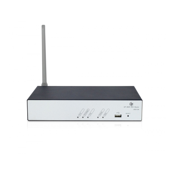
Appendix A Chassis views and technical specifications Chassis views The figures in this appendix are for illustration only. MSR 930 Figure 34 MSR 930 front view (1) USB port (2) Reset button (RESET) Figure 35 MSR-930 rear view (1) Power adapter receptacle... -
Page 39: Msr 930-Gu
MSR 930-GU Figure 36 MSR 930-GU front view (1) USB port (2) Reset button (RESET) Figure 37 MSR 930-GU rear view (1) 3G antenna main connector (2) Power adapter receptacle (3) Console/AUX port (CON/AUX) (MAIN) (4) Gigabit Ethernet WAN port... -
Page 40: Msr 930-W
Figure 39 MSR 930-GT rear view (1) 3G antenna auxiliary connector (2) Power adapter receptacle (3) Console/AUX port (DIV) (CON/AUX) (4) Gigabit Ethernet WAN port (5) Gigabit Ethernet LAN ports (6) 3G antenna main connector (GE0) (GE1 to GE4) (MAIN) -
Page 41: Msr 930-Dg
MSR 930-DG Figure 42 MSR 930-DG front view (1) 3G antenna auxiliary connector (DIV1) (2) USB port (3) Reset button (RESET) (4) 3G antenna main connector (MAIN1) Figure 43 MSR 930-DG rear view (1) Power adapter receptacle (2) Console/AUX port... -
Page 42: Msr 930-W-Gu
Figure 45 MSR 930-SA rear view (1) Synchronous/asynchronous (2) Gigabit Ethernet WAN port (3) Gigabit Ethernet LAN ports serial port (Serial0) (GE0) (GE1 to GE4) (4) Grounding screw (5) Power adapter receptacle (6) Console/AUX port (CON/AUX) MSR 930-W-GU Figure 46 MSR 930-W-GU front view... -
Page 43: Msr 930-W-Gt
MSR 930-W-GT Figure 48 MSR 930-W-GT front view (1) WLAN antenna port (2) USB port (3) Reset button (RESET) (4) WLAN antenna port Figure 49 MSR 930-W-GT rear view (1) Power adapter receptacle (2) Console/AUX port (3) Gigabit Ethernet WAN port... -
Page 44: Msr 930-W-Lm
Figure 51 MSR 930-LM rear view (1) 4G antenna port (M1) (2) Gigabit Ethernet WAN port (3) Gigabit Ethernet LAN ports (GE0) (GE1 to GE4) (4) GPS antenna port (5) 4G antenna port (M0) (6) Grounding screw (7) Power adapter receptacle... -
Page 45: Technical Specifications
Technical specifications MSR 930- Item MSR 930 MSR 930-GU MSR 930-GT MSR 930-W Console/AUX port USB port GE WAN port GE LAN port Serial port LTE FDD (China Built-in WCDMA (China CDMA2000 Unicom) and 3G/4G Unicom) (China Telecom) LTE TDD... - Page 46 MSR 930-W- MSR 930-W- MSR 930-W- Item MSR 930-DG MSR 930-SA Console/AUX port USB port GE WAN port GE LAN port Serial port LTE FDD CDMA2000 (China Built-in (China WCDMA CDMA2000 Unicom) and 3G/4G Telecom) and (China Unicom) (China Telecom)
-
Page 47: 4G Antenna Specifications
4G antenna specifications Item Specification Frequency range 698-960 MHz/1710-2700 MHz Voltage Standing Wave Ratio (VSWR) < 2.5 Input impedance 50 ohms Gain 2 dBi Max power consumption Input interface TNC male Length 214 mm (8.43 in) Color Black Weight 50 g (0.11 lb, estimated) Operating temperature –40°C to +85°C (–40°F to +185°F) 3G antenna specifications... - Page 48 Item Specification Color Black Weight 25 g (0.06 lb) Operating temperature –10°C to +60°C (14°F to 140°F)
-
Page 49: Appendix B Leds
Appendix B LEDs LEDs MSR 930 Figure 54 Front panel LEDs (1) System status LED (SYS) (2) Network status LED (INTERNET) (3) VPN status LED (VPN) Figure 55 Rear panel LEDs (1) GE port status LED (yellow) (2) GE port status LED (green) -
Page 50: Msr 930-Gt
Figure 57 Rear panel LEDs (1) GE port status LED (yellow) (2) GE port status LED (green) MSR 930-GT Figure 58 Front panel LEDs (1) System status LED (SYS) (2) Network status LED (INTERNET) (3) VPN status LED (VPN) (4) 3G status LED (WWAN) -
Page 51: Msr 930-W
MSR 930-W Figure 60 Front panel LEDs (1) System status LED (SYS) (2) Network status LED (INTERNET) (3) VPN status LED (VPN) (4) WLAN status LED (WLAN) Figure 61 Rear panel LEDs (1) GE port status LED (yellow) (2) GE port status LED (green) -
Page 52: Msr 930-Sa
Figure 63 Rear panel LEDs 1 2 1 2 (1) GE port status LED (yellow) (2) GE port status LED (green) MSR 930-SA Figure 64 Front panel LEDs (1) System status LED (SYS) (2) Network status LED (INTERNET) (3) VPN status LED (VPN) -
Page 53: Msr 930-W-Gu
MSR 930-W-GU Figure 66 Front panel LEDs (1) System status LED (SYS) (2) Network status LED (3) VPN status LED (VPN) (INTERNET) (4) WLAN status LED (WLAN) (5) 3G status LED (WWAN) (6) Received 3G signal strength indication LED (RSSI) -
Page 54: Msr 930-Lm
Figure 69 Rear panel LEDs (1) GE port status LED (yellow) (2) GE port status LED (green) MSR 930-LM Figure 70 Front panel LEDs (1) System status LED (SYS) (2) Network status LED (3) VPN status LED (VPN) (INTERNET) (4) GPS status LED (GPS) -
Page 55: Msr 930-W-Lm
MSR 930-W-LM Figure 72 Front panel LEDs (1) System status LED (SYS) (2) Network status LED (3) VPN status LED (VPN) (INTERNET) (4) WLAN status LED (WLAN) (5) 4G status LED (WWAN) (6) Received 4G signal strength indication LED (RSSI) - Page 56 Location Status Description No IPSec VPN tunnel is present. VPN status LED Front panel (VPN) Steady on A minimum of one IPSec VPN tunnel is present. No link is present or no wireless network is available. The router has been connected to the wireless Steady green network and is operating in 3G mode.
- Page 57 Location Status Description Serial port link No link is present. status LED Rear panel Steady green A link is present. (LINK)
Need help?
Do you have a question about the MSR 930 and is the answer not in the manual?
Questions and answers