H3C MSR 930 Installation Manual
Hide thumbs
Also See for MSR 930:
- Installation manual (57 pages) ,
- Installation, quick start (4 pages) ,
- Configuration manual (80 pages)
Table of Contents
Advertisement
Quick Links
Download this manual
See also:
Configuration Manual
Advertisement
Table of Contents

Related Manuals for H3C MSR 930


Summary of Contents for H3C MSR 930
-
Page 1: Installation Guide
H3C MSR 930 Routers Installation Guide Hangzhou H3C Technologies Co., Ltd. http://www.h3c.com Document version: 6W100-20130301... - Page 2 Copyright © 2013, Hangzhou H3C Technologies Co., Ltd. and its licensors All rights reserved No part of this manual may be reproduced or transmitted in any form or by any means without prior written consent of Hangzhou H3C Technologies Co., Ltd.
- Page 3 Preface The H3C MSR 930 Routers Installation Guide includes five chapters, which describe the preparing for installation, installing the router, troubleshooting, chassis views and technical specifications, and LEDs. This preface includes: Audience • • Conventions About the H3C MSR 930 documentation set •...
-
Page 4: Obtaining Documentation
Obtaining documentation You can access the most up-to-date H3C product documentation on the World Wide Web at http://www.h3c.com. Click the links on the top navigation bar to obtain different categories of product documentation: [Technical Support & Documents > Technical Documents] –... -
Page 5: Technical Support
Technical support service@h3c.com http://www.h3c.com Documentation feedback You can e-mail your comments about product documentation to info@h3c.com. We appreciate your comments. -
Page 6: Table Of Contents
Scenario 1 ······························································································································································ 23 Scenario 2 ······························································································································································ 24 Scenario 3 ······························································································································································ 24 Reset button usage guidelines ······························································································································ 24 Appendix A Chassis views and technical specifications ························································································ 25 Chassis views ································································································································································· 25 MSR 930 ································································································································································ 25 MSR 930-GU ························································································································································· 26 MSR 930-GT ·························································································································································· 26... - Page 7 MSR 930-DG ························································································································································· 27 MSR 930-SA ·························································································································································· 28 Technical specifications ················································································································································· 28 Antenna specifications ··················································································································································· 29 Appendix B LEDs ························································································································································ 30 LEDs ················································································································································································· 30 MSR 930 ································································································································································ 30 MSR 930-GU ························································································································································· 31 MSR 930-GT ·························································································································································· 31 MSR 930-DG ························································································································································· 32 MSR 930-SA ··························································································································································...
-
Page 8: Preparing For Installation
Preparing for installation Safety recommendations WARNING! Compliance and Safety Guide Before installation and operation, read all of the safety instructions in supplied with your router. Follow these general safety recommendations: • Turn off all power and remove all power cables before opening the chassis. Unplug all power and external cables before moving the chassis. -
Page 9: Esd Prevention
Max. (mg/m 0.05 0.01 To prevent overheating: Provide adequate clearance for air flow, including at least 10 cm (3.94 in) ventilation space • around the router's air intake and outlet vents. • Make sure the site has an adequate cooling system. ESD prevention To prevent the electronic components from being damaged by ESD, follow these guidelines: •... -
Page 10: Installation Tools
Installation tools Accessories provided with the router • Power cord Console cable • • Ring terminal User-supplied tools and equipment Phillips screwdriver • • Flat-blade screwdriver Wire-stripping pliers, needle-nose pliers • Screws with various specifications • Meters and equipment such as HUB, terminal, and multimeter •... - Page 11 Item Requirements Yes No • The grounding cable of the chassis is grounded properly. • The grounding terminal of the AC power receptacle is grounded properly. Lightning protection • A port lightning arrester is installed. (Optional.) • A power lightning arrester is installed. (Optional.) •...
-
Page 12: Installing The Router
Keep the tamper-proof seal on a mounting screw on the chassis cover intact, and if you want to open • the chassis, contact H3C for permission. Otherwise, H3C shall not be liable for any consequence. Installation prerequisites You have read "Preparing for... -
Page 13: Installing The Router
Figure 1 Installation flowchart Installing the router When installing the router:... -
Page 14: Mounting The Router On A Workbench
Mark the locations of the two mounting holes on the wall with the separations listed as follows: Router model Separation MSR 930, MSR 930-GU, and MSR 930-GT 180 mm (7.09 in) MSR 930-DG, and MSR 930-SA 240 mm (9.45 in) The holes must be level (on the same horizontal line.) -
Page 15: Grounding The Router
Figure 3 Wall-mounting the router Grounding the router WARNING! Connecting the router grounding cable correctly is crucial for protecting the router from lightning and EMI. The grounding resistance should be less than 5 ohms. You can ground the router with a grounding strip or to a buried grounding conductor. The router provides only a ring terminal but no grounding cable. - Page 16 Cover the joint with the insulation covering, and heat the insulation covering with a blow dryer to completely cover the metal part. Figure 4 Attaching the ring terminal Grounding the router with a grounding strip Remove the grounding screw from the router chassis. Put the ring terminal of the grounding cable on the grounding screw.
-
Page 17: Installing A Sim Card
Grounding the router to a buried grounding conductor If the installation site has no grounding strips but offers the option of grounding to earth, hammer a 0.5 m (1.64 ft) or longer angle iron or steel tube into the earth to serve as a grounding conductor, as shown in Figure Figure 6 Grounding to a conductor buried in the earth... - Page 18 Figure 8 Installing the SIM card Position the socket cover and use a screwdriver to fasten the screws on the cover. Figure 9 Installing the cover CAUTION: • To avoid damage to the holder, use proper strength when you install the SIM card. •...
-
Page 19: Installing A 3G Antenna
WCDMA) cards are associated with the antenna connectors on the front and rear panel, respectively. When you install a 3G antenna on a dual-3G MSR 930-DG router, choose the correct connectors. Figure 12 SIM card locations on a dual-3G MSR 930-DG router... -
Page 20: Installing A 3G Antenna Extension Cable
Figure 13 SIM cards and antenna connectors Installing a 3G antenna extension cable The 3G antenna extension cable is not supplied with the router. Prepare it yourself. To install a 3G antenna extension cable: Thread the male connector of the cable through the hole on the bracket, and use screws (from behind the bracket) to secure the male connector to the bracket. -
Page 21: Connecting The Console Cable And Setting Terminal Parameters
Connect the other end of the cable to the peer device. Examine the port LED status. For more information, see "LED description." Figure 15 Connecting the router to a computer Connecting a synchronous/asynchronous serial port cable Verify the port type of the peer device and choose a serial port cable of correct type. Plug the D28 end of the serial port cable into the D28 port of the SAE interface module. -
Page 22: Setting Console Terminal Parameters
Connect the DB-9 connector (female) of the console cable to the RS-232 serial port of the console terminal and the RJ-45 connector to the console port of the router. Figure 17 Connecting the console cable Setting console terminal parameters To set console terminal parameters: Select Start >... - Page 23 Figure 19 Setting the serial port used by the HyperTerminal connection Set Bits per second to 9600, Data bits to 8, Parity to None, Stop bits to 1, and Flow control to None, and click OK. NOTE: To restore the default settings, click Restore Defaults. Figure 20 Setting the serial port parameters...
- Page 24 Select File > Properties in the HyperTerminal window. Figure 21 HyperTerminal window On the Settings tab, set the emulation to VT100 or Auto Detect, and click OK. Figure 22 Setting the terminal emulation parameters...
-
Page 25: Connecting The Power Adapter
Connecting the power adapter The router's power adapter converts AC power to DC power, as follows: AC rated voltage range: 100 VAC to 240 VAC @ 50 Hz to 60 Hz • • DC Rated voltage: 12 VDC To connect the power adapter, as shown in Figure Make sure the router is properly grounded. -
Page 26: Startup Process
System is starting... Booting Normal Extend BootWare The Extend BootWare is self-decompressing......Done! **************************************************************************** H3C MSR930 BootWare, Version 0.00 **************************************************************************** Copyright (c) 2004-2012 Hangzhou H3C Technologies Co., Ltd. Compiled Date : Aug 19 2012 CPU Type : P1010 CPU L1 Cache... -
Page 27: Power-On Check
Configuring basic settings for the router After the router is powered on for the first time, configure basic settings for the router. For more information, see H3C MSR Router Series Configuration Guide and H3C MSR Router Series Command Reference. -
Page 28: Troubleshooting
Keep the tamper-proof seal on a mounting screw on the chassis cover intact, and if you want to open • the chassis, contact H3C for permission. Otherwise, H3C shall not be liable for any consequence. Power supply failure If the router cannot be powered on and LEDs on the front panel are off, it indicates that the power supply is faulty. -
Page 29: No Response From The Serial Port
If you specify the simple keyword, the password is stored in plain text. You can use the display current-configuration command to view the password in the current configuration. After modifying the user password, save it by executing the save command. H3C recommends saving the modifications as the default configuration file. -
Page 30: Sim Card And 3G Antenna Failures
On the main BootWare menu, select 8. This setting (Clear Super Password) is valid only for the first reboot of the router. The super password is restored after the second reboot. ========================<EXTEND-BOOTWARE MENU>======================== |<1> Boot System |<2> Enter Serial SubMenu |<3>... -
Page 31: Scenario 2
Press the Reset button for a short time to reboot the router. Reset button usage guidelines An MSR 930 router provides the Reset button. You can use the button to reboot the system or restore the factory settings. Press the Reset button for a short time to reboot the router. -
Page 32: Appendix A Chassis Views And Technical Specifications
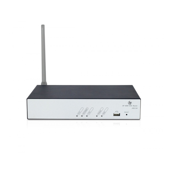
Appendix A Chassis views and technical specifications The MSR 930 routers include the following models: MSR 930, MSR 930-GU, MSR 930-GT, MSR 930- DG, and MSR 930-SA. Chassis views The figures in this appendix are for illustration only. MSR 930... -
Page 33: Msr 930-Gu
MSR 930-GU Figure 26 MSR 930-GU front view (1) USB port (2) Reset button Figure 27 MSR 930-GU rear view (1) 3G antenna main connector (MAIN) (2) Power adapter port (3) Console/AUX port (4) Ethernet WAN port (GE0) (5) Ethernet LAN ports (GE1 to... -
Page 34: Msr 930-Dg
Figure 29 MSR 930-GT rear view (1) 3G antenna auxiliary connector (DIV) (2) Power adapter port (3) Console/AUX port (4) Ethernet WAN port (GE0) (5) Ethernet LAN ports (GE1 (6) 3G antenna main to GE4) connector (MAIN) (7) Grounding screw... -
Page 35: Msr 930-Sa
MSR 930-SA Figure 32 MSR 930-SA front view (1) USB port (2) Reset button Figure 33 MSR 930-SA rear view (1) Synchronous/asynchronous serial (2) Ethernet WAN port (GE0) (3) Ethernet LAN ports (GE1 to port (Serial0) GE4) (4) Grounding screw... -
Page 36: Antenna Specifications
Item 930-GU 930-GT 930-DG 930-SA Dimensions (H 44.2 × 300 × W × D) × 200 mm (excluding 43.6 × 230 × 160 mm (1.72 × 9.06 × 6.30 in) (1.74 × rubber feet 11.81 × and mounting 7.84 in) brackets) 1.0 kg (2.20 1.6 kg (3.53... -
Page 37: Appendix B Leds
Appendix B LEDs LEDs MSR 930 Figure 34 Front panel LEDs (1) System status LED (SYS) (2) Network status LED (INTERNET) (3) VPN status LED (VPN) Figure 35 Rear panel LEDs (1) GE port status LED (yellow) (2) GE port status LED (green) -
Page 38: Msr 930-Gu
MSR 930-GU Figure 36 Front panel LEDs (1) System status LED (SYS) (2) Network status LED (INTERNET) (3) VPN status LED (VPN) (4) 3G status LED (WWAN) (5) Received 3G signal strength indication LED (RSSI) Figure 37 Rear panel LEDs... -
Page 39: Msr 930-Dg
Figure 39 Rear panel LEDs (1) GE port status LED (yellow) (2) GE port status LED (green) MSR 930-DG Figure 40 Front panel LEDs (1) System status LED (SYS) (2) Network status LED (INTERNET) (3) VPN status LED (VPN) (4) 3G status LED (WWAN) -
Page 40: Msr 930-Sa
MSR 930-SA Figure 42 Front panel LEDs (1) System status LED (SYS) (2) Network status LED (INTERNET) (3) VPN status LED (VPN) Figure 43 Rear panel LEDs (1) GE port status LED (yellow) (2) GE port status LED (green) (3) Serial port data receiving status LED (ACT) - Page 41 Location Status Description No link is present or no 3G network is available. The router has been connected to the wireless Steady green network and is operating in 3G mode. Data is being received or transmitted. The router is Flashing green (8 Hz) WWAN Front panel operating in 3G mode.
-
Page 42: Index
Index A C I L P R S T Password loss,22 Power supply failure,21 Antenna specifications,29 Powering on the router,18 Pre-installation checklist,3 Chassis views,25 Restoring the factory settings,23 Installation flowchart,5 Installation prerequisites,5 Safety recommendations,1 Installation tools,3 SIM card and 3G antenna failures,23 Installing the router,6...
Need help?
Do you have a question about the MSR 930 and is the answer not in the manual?
Questions and answers