
Related Manuals for WamBam NERVOUS NELLY VG25100


Summary of Contents for WamBam NERVOUS NELLY VG25100
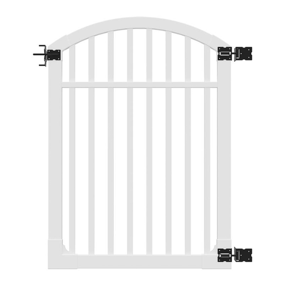
- Page 1 VG25100 ASSEMBLY INSTRUCTIONS NERVOUS ASSEMBLY NELLY INSTRUCTIONS VG25100 VINYL GATE (66” H X 48” W) 60 MIN Approximate assembly time Want to see a video on how to assemble this product? Scan the QR code WWW.WAMBAMFENCE.COM WWW.WAMBAMFENCE.COM VER. 052021...
- Page 2 VG25100 ASSEMBLY INSTRUCTIONS GENERAL IMPORTANT INFORMATION Check the inside of the larger pieces in your box for other materials packed inside. When assembling components, place on a non-abrasive surface (i.e. shipping box) to avoid scratching. We recommend an area approximately 5’x 8’ for unobstructed assembling.
- Page 3 VG25100 ASSEMBLY INSTRUCTIONS INFORMATION GENERAL 1. Read over fence instructions first. Your gate and fence will work better together if you first take the time to read and understand your fence. 2. Pre-assemble the gate frame. Please do not screw the gate frame together until you have temporarily assembled the gate frame.
- Page 4 ASSEMBLY INSTRUCTIONS DETAILED PRODUCT DIMENSIONS AND SPECIFICATIONS 3.56in. 1.5in. 7.75in. 1.5in. 68in. 61.5in. 66.05in. 46.75in. 36in. 43.88in. Ground 4.40in. 7.75in. 3.5in. 50in. 40.75in. 44in. 54.5in. 48in. WamBam Anchor 1.5in. 1.5in. (Large) 3.5in. 1.5in. 3.5in. 3.5in. 1.5in. 3.5in. .090in. wall thickness WWW.WAMBAMFENCE.COM...
- Page 5 VG25100 ASSEMBLY INSTRUCTIONS LAY OUT MATERIALS STEP 1: Hinge (2) Corner Bracket (2) Arch Bracket (2) Metal Post Stabilizer (1) Latch Catch (1) Top Rail (1) Bottom Rail (1) Middle Rail (1) Latch Finger (1) 1½” x 3½” x 42⅛” 1½”...
- Page 6 VG25100 ASSEMBLY INSTRUCTIONS INSTALL GATE JIG, POST ANCHORS, AND POSTS STEP 2: STEP 2.1 STEP 2.2 Identify the location of your gate. Dig a trench Identify the location of the Metal Post 60” long x 6” wide x 5½” deep. Stabilizer and pound it into the ground.
- Page 7 VG25100 ASSEMBLY INSTRUCTIONS STEP 2.7 Make sure to fasten the fence panels before attaching the gate. ASSEMBLE THE GATE FRAME BOTTOM AND SIDES STEP 3: STEP 3.1 Insert the Bottom Rail until it bottoms out inside the Corner Bracket (A). Note: The bottom rail is ribbed internally.
- Page 8 VG25100 ASSEMBLY INSTRUCTIONS STEP 3.2 Insert the bottom rail until it bottoms out inside of the opposite corner bracket. Ensure the width of the gate should be 48”. 48” STEP 3.3 Insert (2) Vertical Stiles into the corner brackets until they hit the bottom rail. Fasten the bottom brackets using (4) 11/4”...
- Page 9 VG25100 ASSEMBLY INSTRUCTIONS ASSEMBLE THE GATE FRAME TOP STEP 4: STEP 4.1 Insert the Top Rail inside the Arch Brackets as illustrated. Insert fully to this point. Insert all the way to this point. Insert fully to this point. INSERT PICKETS AND FINISH ASSEMBLY STEP 5: STEP 5.1...
- Page 10 VG25100 ASSEMBLY INSTRUCTIONS SECURE GATE FRAME AND CORNER BRACKETS STEP 6: STEP 6.1 Screw the brackets with (12) 11/4” white self-drilling stainless steel screws as illustrated. The corner-to-corner measurement must be the same to ensure the gate is square and the width of the gate should be 48”.
- Page 11 VG25100 ASSEMBLY INSTRUCTIONS FASTEN HINGES AND GATE LATCH STEP 7: STEP 7.1 Fasten the Latch Finger onto the arch bracket using (6) 11/4” Black Self-Drilling Stainless Steel Screws (O). Fasten the Hinges onto the opposite arch bracket and bottom bracket using (12) black self-drill- ing stainless steel screws.
- Page 12 VG25100 ASSEMBLY INSTRUCTIONS ASSEMBLE AND FASTEN GATE BRACE STEP 8: STEP 8.1 Assemble the Gate Brace by sliding the larger square tube over the smaller square tube. Align holes and install included hardware. STEP 8.2 Double check that the gate is square and then fasten the gate brace into place with (4) self-drilling stainless steel screws packaged with the brace.
- Page 13 VG25100 ASSEMBLY INSTRUCTIONS ALIGN GATE AND SECURE HINGES TO POST STEP 9: STEP 9.1 Align the gate to the horizontal fence rails. Note: Both the fence & gate horizon- tal rail spacing can be adjusted freely to lower heights. STEP 9.2A Fasten the hinges to the posts with (6) total 2”...
- Page 14 VG25100 ASSEMBLY INSTRUCTIONS STEP 9.2B How to position the screws on the post side of the hinge: Using a ⅛” drill bit, pre-drill the holes for the hinge screws as illustrated. Angle your drill slightly as illustrated. Note: Swing the gate open and pre-drill four more holes for the hinge screws as illustrated.
- Page 15 VG25100 ASSEMBLY INSTRUCTIONS LEVEL GATE AND ADJUST HINGES STEP 10: STEP 10.1 STEP 10.2 Using a level, make sure that the gate fits and The hinges can be adjusted moderately to functions with its latching post. bring gate into level alignment with post. STEP 10.3 To set the tension on the gate hinge, insert the 23/4”...
- Page 16 VG25100 ASSEMBLY INSTRUCTIONS INSTALL LATCH CATCH STEP 11: STEP 11.1 Align and fasten the Latch Catch to fit and function with the latch finger using (6) 11/4” black self-drilling stainless steel screws. Congratulations! You did it! Go grab a beverage of your choice, admire your handiwork, and show us what you got by entering our annual photo contest! WWW.WAMBAMFENCE.COM...
- Page 17 VG25100 ASSEMBLY INSTRUCTIONS INSTALL OVER A ALTERNATIVE APPLICATION: SIDEWALK OR PATH STEP 1.1 Option 1: If the sidewalk is less than 52”, use the gate jig as a temporary spacer. Proceed installing the panels according to the fence’s install guide. Sidewalk/path INSTALL OVER A ALTERNATIVE APPLICATION:...
- Page 18 VG25100 ASSEMBLY INSTRUCTIONS 6935 Reames Rd. Ste. K. Charlotte, NC 28216 hmmm@wambamfence.com 704-892-5222 877-778-5733 WWW.WAMBAMFENCE.COM WWW.WAMBAMFENCE.COM...
Need help?
Do you have a question about the NERVOUS NELLY VG25100 and is the answer not in the manual?
Questions and answers