Interlogix Simon XT Installation Manual
Hide thumbs
Also See for Simon XT:
- Installation manual (74 pages) ,
- User manual (50 pages) ,
- Installation instructions manual (10 pages)
Table of Contents
Advertisement
Quick Links
Interlogix Simon XT Installation Guide - Verizon VoLTE
The LTE Module for Simon XT, XTi, and XTi-5 enables wireless reporting of all alarms and other system events from the
Interlogix Simon XT, XTi, and XTi-5 control panel on the Verizon LTE wireless (cellular) network. The module can be
used as the primary communication path for all alarm signaling, or as a backup to a telephone line connection to the
monitoring station. The wireless alarm signaling and routing service are operated by Alarm.com.
The LTE Module also features integrated support for Alarm.com's emPower™ solution with built-in Z-Wave capabilities
and for Alarm.com's Image Sensor when the Image Sensor daughterboard is added or an Image Sensor radio is built-in.
Two-way voice over LTE is supported on module firmware versions 185 and above.
The module interfaces with the Simon XT, XTi, and XTi-5 panels, fits into a special compartment inside the panel, and is
powered by the control panel and panel battery.
Specifications
Compatible
Power requirements
Standby current
Peak current
Operating temperature
Storage temperature
Max. relative humidity
Cellular network
https://answers.alarm.com/ADC/Partner/Installation_and_Troubleshooting/Panels/Interlogix_Simon_XT/Interlogix_Simon_XT_...
Simon XT panels with software versions 1.3 and later
and Simon XTi
6V nominal
30mA (10mA in PowerSave Mode)
1.7 A
32 to 120°F (0 to 49°C)
-30 to 140°F (-34 to 60°C)
90% non-condensing
LTE
Updated: Tue, 31 Mar 2020 20:51:49 GMT
1
Advertisement
Table of Contents

Subscribe to Our Youtube Channel
Related Manuals for Interlogix Simon XT


Summary of Contents for Interlogix Simon XT
- Page 1 Interlogix Simon XT Installation Guide - Verizon VoLTE The LTE Module for Simon XT, XTi, and XTi-5 enables wireless reporting of all alarms and other system events from the Interlogix Simon XT, XTi, and XTi-5 control panel on the Verizon LTE wireless (cellular) network. The module can be used as the primary communication path for all alarm signaling, or as a backup to a telephone line connection to the monitoring station.
-
Page 2: Account Creation
Account creation Before installing an Alarm.com LTE Module in a Simon XT, XTi, or XTi-5 system, a new customer account needs to be created with Alarm.com. It is recommended to create the account at least 24 hours in advance of installation to ensure that the radio is activated prior to installation. - Page 3 1. Open the panel by pressing the two tabs on the top of the XT or by lifting the tabs on the XTi and XTi-5 panel, as shown in Figure 1. Figure 1: Top View of Simon XT, XTi, and XTi-5 panels 2. The module compartment can be found behind the front panel that swings down, to the left of the battery compartment as seen in Figure 2.
- Page 4 3. Push the antenna end into open module connector to snap the antenna onto the module. The module must be seated correctly beneath the two small, plastic corner tabs, as shown in Figure 3, to ensure it fits into the compartment properly.
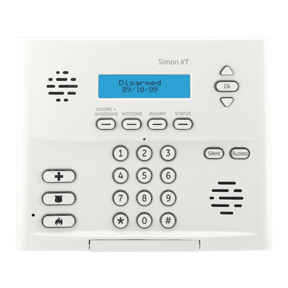
- Page 5 LTE Phone Test (module registration) To initiate module communication with Alarm.com and the LTE network the first time, perform a LTE phone test. To perform a Phone Test on a Simon XT: 1. Press the arrow to scroll to System Test, then press OK.
- Page 6 2. The panel will display LTE Comm Test in progress to indicate the test has been imitated. The Simon XT, XTi, and XTi-5 panel will let you know when the LTE Phone Test has completed by displaying LTE Test signal sent OK on the panel screen. This indicates that Alarm.com has received and acknowledged the signal. This does not guarantee that the signal went through to a monitoring station;...
- Page 7 To verify module status using the Simon XT versions 1.3+: 1. Press the arrow to scroll to System Test, then press OK. 2. Enter the installer code (default 4321) or master code (default 1234). 3. Press the arrow to scroll to Interactive Services, then press OK.
-
Page 8: Troubleshooting Leds
Keypad long presses for module status In addition, some of the information can be retrieved on the Simon XT via long key presses from the keypad. Press and hold the following panel keys for 10 seconds to display the given information on the panel display. Most messages are displayed for less than 30 seconds but can be cut short by pressing [#] for 10 seconds. - Page 9 The following table below describes the LED functions. Function Error LED. Flashes one to eight times in an eight-second interval to indicate the specific error. See LED L1 (red) for errors and common fixes. Panel Communication and Z-Wave status messages. Flashes every time the module communicates with the panel and flashes in patterns to indicate Z-Wave status.
- Page 10 Table 4: Errors flashed on L1 (red) Number of flashes Error and solution The module cannot communicate with the panel. Perform a power cycle on the panel. If the error persists lift the module out of the panel and re-insert it. If the error is still observed try a different module.
- Page 11 Number of flashes Error and solution The module is not compatible with this panel type. Please insert a compatible module. If it persists, the account may have been set up incorrectly. Contact Alarm.com Technical Support. You will be asked to check the serial number of the module. LED L2 (yellow) L2 flashes with every communication between the module and the panel.
- Page 12 LED 2 Device status or error Description The device you attempted to add to Add node attempt failed because a network is already in a network Solid with one blink node already in the network (lasts 60 and must be deleted before it can seconds).
-
Page 13: Various Module States (Modes)
LED flashes Device status or error Description No Home ID present (lasts until the When the LTE module first connects 6-blink module connects to Alarm.com and to Alarm.com it is configured with a is configured) necessary unique network ID Various module states (modes) There are three module states, or modes, as described below: Idle mode AC power is OK and the module is not currently talking to Alarm.com. -
Page 14: Improving Wireless Signal Strength
L2 - Communication with the panel. L3 - Communication with Alarm.com. L4 - Alternates two seconds on, then two seconds off. L5 - Inactive Sleep mode The panel is not connected to AC power, or there is an AC power failure, and the battery level is low. The module will connect to Alarm.com to send a signal, but will otherwise draw almost no power. - Page 15 Simon XT 1.3 and up Interactive Services menu Table 6: Simon XT 1.3 and up Interactive Services menu Menu Description Scroll down to System Programming, enter the System Programming + Installer Code Installer Code and press OK - Interactive Services...
- Page 16 Press OK to enter Z-Wave Add Mode. Make sure the device you are trying to add is powered up and within 3 to 6 feet of the Simon XT or XTi panel. Refer to the --- Add Z-Wave Device manufacturer’s instructions for button presses required to enroll the device.
- Page 17 Menu Description Press “OK” to enter Add Mode. Enroll the Image Sensor --- Learn Image Sensor by inserting batteries or resetting. Press “OK” and scroll to the Image Sensor to delete. --- Delete Image Sensor Press “OK” to delete. Press “OK” and scroll to the Image Sensor of interest. ---Image Sensor Settings Press “OK”.
- Page 18 Menu Description Scroll down to System Test, enter the Installer Code System Test + Installer Code and press OK - Interactive Services Scroll up to Interactive Services and press OK This menu is used to automate the process of confirming that all sensors report correctly to the Monitoring Station.
- Page 19 Menu Description The Z-Wave node id of the Z-Wave thermostat. If 0, then the Z-Wave thermostat has not been found. You may ---- Node ID need to troubleshoot the Z-Wave network via the Z-Wave Setup menu. Press “OK” to have the module try to find the thermostat again.
-
Page 20: Contact Information
Menu Description For troubleshooting only. Shows how many unsuccessful attempts were made by the LTE module at trying to ---- Last Temp. Read communicate with the Z-Wave thermostat. A low number of 0 or 1 is normal. Press OK if the weather forecast is not showing on the -- Request Weather Update touch screen (2WTTS). - Page 21 • Increase the separation between the equipment and receiver. • Connect the equipment into an outlet on a circuit different form that which the receiver is connected • Consult the dealer or an experienced radio/TV technician for help. Operation is subject to the following two conditions: 1.
Need help?
Do you have a question about the Simon XT and is the answer not in the manual?
Questions and answers