Table of Contents
Advertisement
Quick Links
Interlogix Simon XTi Image Sensor Installation Guide - ADC-IS-300-LP
PRODUCT SUMMARY & TECHNICAL SPECIFICATIONS
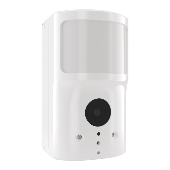
The Image Sensor is a pet immune PIR (passive infrared) motion detector with a built-in camera designed to capture
images during alarm or non-alarm events when motion is detected.
Product Features:
• Communicates wirelessly to the security control panel
• 35 foot detection range with a 90 degree horizontal FOV
• Configurable PIR sensitivity and pet immunity settings
• Image: VGA 640x480 pixels
• Color Images (except in night vision)
• Night vision image capture with infrared flash (black & white)
• Tamper detection, walk test mode, supervision
• All systems can support up to three Image Sensors
• UL 639 certified
Technical Specifications:
• Alarm.com Model Number: ADC-IS-300-LP
• Interlogix Part Numbers:
• Power Source: Recommended 2 AA 1.5v Energizer Ultimate Lithium Batteries.
• Batteries: Refer to the Batteries section for details
https://answers.alarm.com/Installation_and_Troubleshooting/Image_Sensor/Interlogix_Simon_XTi_Image_Sensor/Interlogix_Simon_XTi_I
Updated: Tue, 17 Apr 2018 13:48:15 GMT
1
Advertisement
Table of Contents

Subscribe to Our Youtube Channel
Related Manuals for Interlogix ADC-IS-300-LP


Summary of Contents for Interlogix ADC-IS-300-LP
- Page 1 Interlogix Simon XTi Image Sensor Installation Guide - ADC-IS-300-LP PRODUCT SUMMARY & TECHNICAL SPECIFICATIONS The Image Sensor is a pet immune PIR (passive infrared) motion detector with a built-in camera designed to capture images during alarm or non-alarm events when motion is detected.
-
Page 2: Hardware Compatibility Requirements - By Panel
• Operating Temperature Range: 60° to 80°F • Weight: 3.1 oz. (with batteries and without mounting accessories) • Dimensions: 3.1’’ h x 1.8’’ w x 2.3’’ d • Supervisory Interval: 100 minutes (sensor), 3 hours (alarm hardwire) • Wireless Signal Range: Greater than 400 ft open air •... -
Page 3: Camera Led Reference Chart
BATTERIES Battery type: The Image Sensor uses 2 AA 1.5v Energizer Ultimate Lithium batteries (UL compliant). Expected Battery Life: Approximately 4 years with lithium batteries. Voltage Thresholds: With lithium batteries, low battery alerts are issued at 3.05V. The sensor cannot operate when the voltage reads below 2.30V. - Page 4 https://answers.alarm.com/Installation_and_Troubleshooting/Image_Sensor/Interlogix_Simon_XTi_Image_Sensor/Interlogix_Simon_XTi_I Updated: Tue, 17 Apr 2018 13:48:15 GMT...
-
Page 5: Resetting The Image Sensor
RESETTING THE IMAGE SENSOR There are two ways to reset the Image Sensor: • Power Cycle – Power Cycle can be done by one of two ways: (1) Take out and reinsert batteries or (2) press and release the sensor reset button. Only initiate a power cycle if the LED has not been active in the last 10 seconds. After a power cycle, the Image Sensor will enter sensor power up state followed by the memory check state. - Page 6 yellow after the memory check (solid red LED). A network reset will only work if the Image Sensor is not actively communicating with a network. If the Image Sensor is within range of the original panel, it is required that the Image Sensor first be deleted from the panel it was previously learned into before being able to perform a network reset on the Image Sensor.
-
Page 7: Service Plans Requirements
SERVICE PLANS REQUIREMENTS Image capture features require a service plan that includes one of the following Image Sensor add-ons: Images - Alarms- Includes upload of images from alarm events only. Images - Plus- Includes upload of images from alarm events and non-alarm events INSTALLATION: PREPARING PANEL FOR ENROLLMENT 1. - Page 8 Simon XTi/XTi-5 1. Put the panel into add mode. On the panel, scroll until the screen shows “Programming” > Enter installer code (default 4-3-2-1) > Select “Interactive Services” > Select “Image Sensor” > Select “Add” > The screen will display “Reset or power-up sensor to enroll…”...
-
Page 9: Installation: Mounting Image Sensor
11. The Image Sensor LED will alternate between green and yellow while the customer’s device list is updated with Alarm.com. The LED will turn solid green when the Image Sensor has been successfully added to the customer’s account. Note: If you move (tamper) the Image Sensor after the LED has turned solid green, the Image Sensor will enter test mode for 3 minutes indicated by red LED when motion is detected. - Page 10 2. Screw bracket to back plate. https://answers.alarm.com/Installation_and_Troubleshooting/Image_Sensor/Interlogix_Simon_XTi_Image_Sensor/Interlogix_Simon_XTi_I Updated: Tue, 17 Apr 2018 13:48:15 GMT...
- Page 11 3. Determine location to mount sensor. 4. Choose applicable mounting bracket. The sensor hardware packet contains two mounting brackets for different mounting scenarios. Use the provided large screws and anchors to attach the bracket to the wall. (Leave at least 3 inches of clearance above the sensor to allow for battery replacement without uninstalling the mounting https://answers.alarm.com/Installation_and_Troubleshooting/Image_Sensor/Interlogix_Simon_XTi_Image_Sensor/Interlogix_Simon_XTi_I Updated: Tue, 17 Apr 2018 13:48:15 GMT...
- Page 12 bracket.) 5. Place sensor with arm on mounting bracket. Adjust the horizontal positioning of the sensor to point towards the desired coverage area. 6. Secure the mounting arm location by sliding lock pin into the hole. Use the washer and remaining small screw to secure the lock pin by screwing upwards through the bottom of the hole in the mounting bracket.
-
Page 13: Deleting Image Sensor From Panel
a. Verify that rules are confirmed via the dealersite or on MobileTech, Resend rules if they are not confirmed. b. Verify RF Coverage by checking that the signal strength is above 40%. The signal strength must be greater than 30% for sensor to function properly. c. -
Page 14: Troubleshooting
Figure 4.Top View: PIR Lens Coverage As indicated in Figure 4, the camera coverage area is narrower than the PIR coverage area. When installing, mount sensor where subjects are likely to be centered in or across PIR and camera field of view. TROUBLESHOOTING General Troubleshooting Steps •... - Page 15 Sensor Non-Responsive • Verify Range: Under the “Image Sensor Setup” menu, scroll to “Image Sensor Settings,” select the sensor and verify under “Signal” that the sensor is registering a strong signal. If signal strength is low, move non-responsive sensor closer to control panel, verify signal strength and see if communication resumes. Be sure that Image Sensor daughterboard antenna is correctly routed as indicated in step 5 of the installation procedure.
Need help?
Do you have a question about the ADC-IS-300-LP and is the answer not in the manual?
Questions and answers