Interlogix Simon XT Installation Manual
Hide thumbs
Also See for Simon XT:
- User manual (50 pages) ,
- Installation manual (21 pages) ,
- Installation instructions manual (10 pages)
Table of Contents
Advertisement
Quick Links
Download this manual
See also:
User Manual
Advertisement
Table of Contents

Related Manuals for Interlogix Simon XT


Summary of Contents for Interlogix Simon XT
- Page 1 Simon XT Installation Manual P/N 466-2265 • REV G • OCT12...
- Page 2 © 2012 UTC Fire & Security Americas Corporation, Inc. Copyright Interlogix is part of UTC Climate Controls & Security, a unit of United Technologies Corporation. All rights reserved. Disclaimer The information in this document is subject to change without notice. UTC Fire &...
- Page 3 License All rights to and in the Licensed Product, including, but not limited to, copyrights, patents, trademarks, and trade secrets, belong to UTC FIRE & SECURITY, and UTC FIRE & SECURITY retains title to each copy of the Software. You agree that UTC FIRE &...
- Page 4 Limited warranty UTC FIRE & SECURITY warrants that for one (1) year from the date of delivery of the Licensed Product (Software Warranty Period), the functions contained in the Software will be fit for their intended purpose as described in the applicable Documentation from UTC FIRE &...
- Page 5 Restricted rights legend The Licensed Product is provided with RESTRICTED RIGHTS. In the event the United States Government or an agency thereof is granted a license, the following additional terms apply: Restricted Computer Software, as defined in the Commercial Computer Software–Restricted Rights clause at Federal Acquisition Regulations 52.227-19, and the restrictions as provided in subparagraphs (c)(1) and (c)(2) thereof;...
- Page 6 If the equipment is causing harm to the telephone network, the telephone company may ask you to disconnect the equipment until the problem is resolved. Contact information www.utcfireandsecurity.com www.interlogix.com Customer support www.interlogix.com/customer-support...
-
Page 7: Table Of Contents
Menu navigation 33 Set clock 34 Set date 34 Revision 35 Contrast 35 System programming 36 Phone numbers 38 Phone options 39 Sensors 40 Reporting 42 Timers 45 Touchpad options 47 System options 47 Siren options 48 Simon XT Installation Manual... - Page 8 Testing 56 Control panel 56 Sensors 57 Phone communication 59 Offsite phone operation 60 Central station communication 60 Two-way voice operation 61 Voice event notification 62 X10 operation 62 Troubleshooting 64 Specifications 65 Sensor names 66 Simon XT Installation Manual...
-
Page 9: Introduction
Devices that respond to commands from the panel Note: The keyfob and X10 modules have not been investigated by UL. Figure 1: Simon XT system Note: The universal, lamp, and appliance modules require a special transformer. The self-contained panel provides the main processing unit for all system functions. -
Page 10: System Components
Water sensors detect water leaks and rising water. The detector is connected to the sensor by an 8-foot cable. Water that (60-744) reaches both detector contact points activates the sensor, causing it to transmit an alarm signal. Simon XT Installation Manual... -
Page 11: Standard Panel
Table 2: Panel hardware capabilities Hardware Capability Power Input for an AC step-down, plug-in style transformer. One siren output, up to two Terminals for connecting hardware sirens or normally closed zone inputs (NC) loop switch circuits. Simon XT Installation Manual... - Page 12 Inspect the package and contents for visible damage. If any components are damaged or missing, do not use the unit; contact the supplier immediately. If you need to return the unit, you must ship it in the original box. Simon XT Installation Manual...
-
Page 13: Planning
1. Disarm. 2. Arm doors and windows. 3. Arm motion sensors. 4. Arm doors/windows and motion sensors. Table 3: Recommended sensor groups Device Recommended sensor group Indoor motion sensor 17 (intrusion), 25 (chime) Simon XT Installation Manual... - Page 14 Portable auxiliary 24-hour portable auxiliary button. Emergency 01234 Siren shut off confirms CS report. Special intrusion: Such as gun cabinets and wall Intrusion 1234 safes. Special intrusion: Such as gun cabinets and wall Intrusion 1234 safes. Simon XT Installation Manual...
- Page 15 PIR motion sensor, sound sensor, or pressure mat. Silent 01234 RF thermostat. No report Auxiliary: Freeze sensor. Trouble 01234 beeps PIR motion sensor or sound sensor. No report. Silent 01234 Carbon monoxide alarm. Emergency 01234 Entry/exit delay interior PIR motion Intrusion Simon XT Installation Manual...
- Page 16 Local instant interior: 24-hour local alarm zone Intrusion 1234 protecting anything that opens and closes. No report. Local special chime. Three 01234 beeps Table 5: Sensor assignment locations Sensor Device Sensor Sensor name/location Notes group Simon XT Installation Manual...
-
Page 17: Cross-Zoning
When the person is detected walking through the kitchen, the motion sensor in the kitchen is tripped, sounding a local alarm. If motion is detected by the living room motion sensor within two minutes, an alarm report will be sent to the central station. Simon XT Installation Manual... -
Page 18: System Configuration
User code 4 None None 3 to 6 digits D, I, M User code 5 None None 3 to 6 digits D, I, M User code 6 None None 3 to 6 digits D, I, M Simon XT Installation Manual... - Page 19 1 to 7, Off D, I Dial delay 30 seconds 15 seconds 15 to 45 seconds D, I Call waiting code None None 26 digits D, I Sensors menu Learn sensors D, I Delete sensors D, I Simon XT Installation Manual...
- Page 20 45 to 254 seconds D, I No activity timeout 2 to 24 hours, off D, I Auto phone test 1 to 254 days, off D, I Supervisory time Midnight None 12:00 midnight to D, I 11:59 PM, None Simon XT Installation Manual...
- Page 21 1 to 10 D, I, M Hardwired siren On/Off D, I supervision Speaker volume 1 to 8 D, I, M Panel silent police On (silent), Off D, I panic (audible) Panel tamper alarm On/Off D, I Simon XT Installation Manual...
-
Page 22: Emergency Planning
Use these guidelines when drawing an emergency floor plan for the homeowner: • Show all building levels. • Show exits from each room. (We recommend two exits per room.) • Show the locations of all security system components. • Show the locations of any fire extinguishers. Simon XT Installation Manual... -
Page 23: Installation
Wireless smoke sensor 60-848-95 learned into sensor group 26 • Panel piezo beeps turned on • Control panel alarms set to on • Siren timeout set to four minutes or more • Trouble beeps set to on • RF jam detect set to on Simon XT Installation Manual... -
Page 24: Sia System Requirements
Table 7: SIA setting requirements Function Default setting Required setting Entry delay 30 seconds 30 to 254 seconds Exit delay 60 seconds 45 to 154 seconds Dialer delay 30 seconds 14 to 45 seconds Autoarm Unvacated premises Simon XT Installation Manual... -
Page 25: Central Station Reporting
Note: Before beginning installation, installers must verify compatibility with the following central station receivers. • Radionics D6600 central station receiver • Sur-Gard central station receiver with models SG-DRL2A and SG-CPM2 • CS5000 digital alarm communicator receiver Simon XT Installation Manual... -
Page 26: Ul Canada Listed Installations
Tabs at the top of the panel secure and release the front cover and the chassis. The plastic hinges on the panel bottom allow the cover and chassis to swing down and out of the way (Figure 3 on page 21). Simon XT Installation Manual... -
Page 27: Mounting The Panel
4. Mount the back piece to the wall through the two horizontally centered mounting holes near the top and bottom using the supplied mounting hardware. Use wall anchors if no studs are present (Figure 4 on page 22). Simon XT Installation Manual... -
Page 28: Connecting Hardwired Devices
The panel has seven screw terminals and two telephone connections (Figure 5 on page 23). The screw terminals connect AC power, sirens, and/or hardwired detectors. Program sensors and devices before you install them. Follow the instructions in to add the sensors to panel memory. Simon XT Installation Manual... - Page 29 Figure 5: Simon XT terminal connections HW1 I/O, HW2 in, and HW1&2 DC out terminals The HW1 I/O terminal is dual purpose and can be used for either siren or hardwired contact connections. The HW2 in terminal is an input only.
- Page 30 Figure 7 on page 25. The resistor must be connected at the last switch in the circuit. Note: Do not install the resistor at the panel terminals. This does not provide supervision of the wire. Simon XT Installation Manual...
-
Page 31: Wiring A Phone Line To The Panel
Full line seizure wiring with an RJ31X 1. Run a four-conductor cable A from the premises Telco block D to the RJ31X 2. Connect the four-conductor cable A wires to the RJ31X B. Simon XT Installation Manual... - Page 32 If a single phone is all that exists on the premises, full line seizure can be accomplished without an RJ31X (Figure 8 above). 1. Disconnect the phone from the premises phone jack and plug it into the panel PHONE jack A. This jack is disconnected automatically whenever the panel reports. Simon XT Installation Manual...
-
Page 33: Wiring The Power Transformer
RJ31X Figure 9: Full line seizure wiring with single landline phone Wiring the power transformer Connect the power transformer to the panel AC terminals as shown in Figure 10 on page 28. Simon XT Installation Manual... - Page 34 5. Push forward and rotate the battery downward until it seats beneath the rear battery compartment latch. Caution: Do not connect the battery until you are ready to power up the panel. See “Powering up the panel” above Simon XT Installation Manual...
-
Page 35: Installing X10 Modules
1. Set the unit code dial to a unit number between 1 and 8. 2. Set the housecode for the installation. 3. Plug the module into a wall outlet. 4. Plug the lamp/appliance into the module. Simon XT Installation Manual... - Page 36 2. Set the housecode for the installation. 3. Set the module switches to momentary and relay only. 4. Connect the module terminals to the desired device terminals. 5. Plug the universal module into a wall outlet. Simon XT Installation Manual...
-
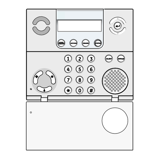
Page 37: Programming
All installer options are set in the System Programming menu, except for setting the system time. Table 9 below explains the panel keys and features shown in Figure 12 below. Figure 12: Simon XT self-contained panel Table 9: Simon XT panel keys and features Control Description Piezo siren The piezo siren makes alarm beeps and status beeps. - Page 38 The panel automatically exits the system menu after a few seconds of inactivity if no access code has been entered yet. After an access code has been entered to access a code-protected area of the system menu, the timeout is 4 minutes. Simon XT Installation Manual...
-
Page 39: Menu Navigation
Enter. The option value will start flashing, indicating that it is ready to be changed. Use the scroll keys or enter a numerical value to change the option, then press the Enter key to save the change. Table 10: Simon XT menu structure Set Clock (system time) Set Date... -
Page 40: Set Clock
The display shows the current time and stops flashing. 6. Press Status twice to exit. Set date If the panel loses both AC and battery power, then upon power restoral the system date will reset. Date format is YYYY-MM-DD, where: YYYY = year Simon XT Installation Manual... -
Page 41: Revision
1. Scroll until the display shows Contrast, and then press OK. 2. Scroll to increase or decrease the contrast setting, 3. Press Status to save the setting and exit. Note: Changes in contrast are more noticeable when not looking at the display straight on. Simon XT Installation Manual... -
Page 42: System Programming
3. Press OK. The panel is now in program mode. Note: Do not remove the panel power while in program mode. Table 11: Simon XT programming codes Code Description Dealer code You can use the dealer code to program all system functions, including high-security options that are not accessible with the installer code if it is different from the dealer code. - Page 43 If other sensors are opened during the exit delay, they will also be bypassed if left open. If group 13 (instant perimeter) sensors are opened during the exit delay, the panel goes into immediate alarm. Simon XT Installation Manual...
-
Page 44: Phone Numbers
To add a pause to the phone number, press Bypass. Pressing OK is Phone #4 Blank required if you enter fewer than 26 digits. Downloader # Blank Lets you program up to a 26-digit phone number for the Enterprise Downloader. Simon XT Installation Manual... -
Page 45: Phone Options
1 = Ring/hang/ring or ten rings 2 = Ring/hang/ring/hang/ring or ten rings 3 = Ring/hang/ring/hang/ring/hang/ring or ten rings 4 = Ten rings 5 = Ring/hang/ring 6 = Ring/hang/ring/hang/ring 7 = Ring/hang/ring/hang/ring/hang/ring Off = Disabled, no remote (offsite) access Simon XT Installation Manual... -
Page 46: Sensors
1. You can override this by entering the desired sensor number using the number keys. To learn (program) a sensor: 1. Scroll until the display shows System Programming, and then press OK. The system prompts for an access code. Simon XT Installation Manual... - Page 47 The display shows Sn ## Grp## <Text>. 5. Scroll until the display shows the sensor you want to delete, and then press The display shows Deleted, and then shows Delete Sensor. 6. Press Status twice to exit. Simon XT Installation Manual...
-
Page 48: Reporting
Reporting Table 16 on page 43 and Table 17 on page 44 describe the Reporting menu. Simon XT Installation Manual... - Page 49 Determines whether the system (armed or disarmed) goes into tamper and reports an alarm anytime a sensor tamper switch is tripped (on), or only when the system is armed and a tamper switch of an armed sensor is tripped (off). Simon XT Installation Manual...
- Page 50 Note: UL has only verified reporting compatibility with the CS5000 Digital Alarm Communicator Receiver. For UL listed systems, Phone 1 Report Mode must be set to All SIA or All CID. Alarms include: Fire, Intrusion, Emergency, Silent, and Alarm Cancels. Simon XT Installation Manual...
-
Page 51: Timers
Determines when the panel reports supervisory conditions (sensor failures) and automatic phone tests to the central station. The panel clock must be set to the correct time for this option and the automatic phone test to work correctly. Simon XT Installation Manual... - Page 52 If this option is off, the time for receiving supervisory signals is determined by RF timeout. Simon XT Installation Manual...
-
Page 53: Touchpad Options
(on) or a standard panel (off). Turning on this feature disables low battery supervision and allows the microphone to remain on continuously during an AVM session. With this option on, the panel is not testing battery supervision. Simon XT Installation Manual... -
Page 54: Siren Options
You can silence trouble beeps by arming or disarming the system or by pressing the STATUS button. Trouble beeps resume later if the trouble condition is not cleared. Simon XT Installation Manual... -
Page 55: Piezo Beep Options
Silent exit. Three beeps sound at the beginning of the exit delay and three more sound just before the exit delay expires. Entry delay. Three beeps sound every 5 seconds and three times per second during the last 10 seconds. Simon XT Installation Manual... -
Page 56: Audio Verification Options
VOX mic gain setting. If the VOX is not switching the speaker on when the central station operator is talking, raise this setting and lower the VOX mic gain setting. Changing this setting does not affect speaker volume. Simon XT Installation Manual... - Page 57 9. Press Enter to accept the new housecode. The panel displays Housecode <new housecode>. 10. Press STATUS twice to exit program mode. To program an entry-activated light: 1. Press the scroll buttons until the panel displays System programming. 2. Press Enter. The panel displays Enter code. Simon XT Installation Manual...
- Page 58 2. Enter your access code and press Enter. The panel displays Access codes. 3. Press the scroll buttons until the panel displays Light control. 4. Press Enter. The panel displays Set entry lights. 5. Press the scroll buttons until the panel displays Set entry lights. 6. Press Enter. Simon XT Installation Manual...
- Page 59 1 to 8 as entry lights (On). 1 through 8 Sensor light # 01 to 40 In this menu, each enrolled sensor can be associated with an X-10 light with unit number from 1 to 8 (or Off for no association). Simon XT Installation Manual...
-
Page 60: System Tests
It is also possible to restore power to the panel by plugging in the transformer first, which allows the panel to be closed so that the tamper switch does not need to be pressed. If you do this, be sure to reconnect the battery. Simon XT Installation Manual... - Page 61 If phone lock is on, phone numbers 1 and 2, downloader phone number, account number, phone lock, downloader code, phone report modes 1 to 4, access code length, and call waiting and dealer code will not reset to their defaults. Simon XT Installation Manual...
-
Page 62: Testing
One beep indicates the system is subdisarmed. The panel displays and speaks “Subdisarmed”. duress codes only), and bypasses 24-hour intrusion sensors (master The Disarm button blinks. access code only). Fire sensors (group 26) cannot be subdisarmed. Simon XT Installation Manual... -
Page 63: Sensors
RF packets received. The system will continue to prompt for sensors that have not yet been tested. When all sensors have been tested, the display shows SN Test Complete Press Status. 3. Press Status. The display shows Sensor Test OK. Simon XT Installation Manual... - Page 64 Emergency buttons (remote handheld touchpads only) 4. Press STATUS. The panel displays Sensor Test Ok. 5. If you press STATUS and the panel has not heard from all sensors, the panel will display Sn test fail or aborted Simon XT Installation Manual...
-
Page 65: Phone Communication
1. Scroll to the Comm Test option under the System Test menu. 2. Press OK. The panel confirms that a communication test has begun. When the communication test is complete, the panel displays Comm Test is OK within 3 minutes. Simon XT Installation Manual... -
Page 66: Offsite Phone Operation
Verification Set) Terminate session Central station communication After performing sensor and communication tests, check that the system is reporting alarms successfully to the central station. Table 31 on page 61 provides a list of sensor/user report codes. Simon XT Installation Manual... -
Page 67: Two-Way Voice Operation
3. Press 99 to terminate the session. Note: Panel voice announcements are silenced during AVM sessions. If the operator does not terminate the session correctly, panel announcements may not occur for up to 90 seconds after the operator hangs up. Simon XT Installation Manual... -
Page 68: Voice Event Notification
1 through 8. The panel responds with Light # on/off. Press the asterisk button (*) twice to turn on all lamp modules. Press the pound button (#) twice to turn off all lamp modules. Simon XT Installation Manual... - Page 69 0.5 seconds off for three beeps then 1.5 seconds off). Note: The X10 siren must be set to unit #9 to “hear” emergency alarms and status beeps. To hear emergency alarms only, set to unit #10. Simon XT Installation Manual...
-
Page 70: Troubleshooting
The latchkey may not be enabled. Enable the latchkey by pressing Motions twice. • The phone number may not be programmed properly. Reprogram the phone number. • The system time may not be set. Set the system time. Sensors If a sensor does not work: Simon XT Installation Manual... -
Page 71: Specifications
32 to 120ºF (0 to 49ºC) Maximum humidity 85% relative humidity, noncondensing Auxiliary power Unregulated 5.3 to 12.3 VDC, with a maximum of 250 mA Size (LxWxD) 7 x 5.75 x 2.125 in. (178 x 146 x 54 mm) Simon XT Installation Manual... -
Page 72: Sensor Names
Master bedroom Master bedroom window 010 Bedroom Bedroom window Child’s room Guest room Guest room window Child’s room window Utility room Living room Living room window Kitchen Kitchen window Porch Porch window Patio door Office Office window Simon XT Installation Manual... - Page 73 Den window Garage Special chime Basement Basement window Upstairs Upstairs window Downstairs Downstairs window Hallway Medicine cabinet Closet Attic System panic Module Phone module ‘ & “ < > (space) Simon XT Installation Manual...
- Page 74 Simon XT Installation Manual...
Need help?
Do you have a question about the Simon XT and is the answer not in the manual?
Questions and answers