
Subscribe to Our Youtube Channel
Related Manuals for WamBam AG14002


Summary of Contents for WamBam AG14002
- Page 1 AG14002 ASSEMBLY INSTRUCTIONS SLIM JIM ASSEMBLY INSTRUCTIONS ALUMINUM GATE AG14002 60 MIN Approximate assembly time Want to see a video on how to assemble this product? Scan the QR code WWW.WAMBAMFENCE.COM WWW.WAMBAMFENCE.COM VER. 031721...
- Page 2 AG14002 ASSEMBLY INSTRUCTIONS GENERAL IMPORTANT INFORMATION Check the inside of the larger pieces in your box for other materials packed inside. When assembling components, place on a non-abrasive surface (i.e. shipping box) to avoid scratching. We recommend an area approximately 5’x 8’ for unobstructed assembling.
- Page 3 AG14002 ASSEMBLY INSTRUCTIONS INFORMATION GENERAL 1. Read over fence instructions first. Your gate and fence will work better together if you first take the time to read and understand your fence. 2. Pre-assemble the gate frame. Please do not screw the gate frame together until you have temporarily assembled the gate frame.
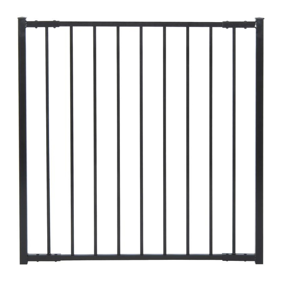
- Page 4 AG14002 ASSEMBLY INSTRUCTIONS DETAILED PRODUCT DIMENSIONS AND SPECIFICATIONS This gate can be trimmed down both in width and height to accommodate custom applications. 50in. 48in. 3.94in. 52in. 48in. 36in. 36in. 2in. Ground Gate Jig (Vinyl) Metal Post Stabilizer String Line 52in.
- Page 5 AG14002 ASSEMBLY INSTRUCTIONS LAY OUT MATERIALS STEP 1: Aluminum Gate Hinge (2) Gate Jig (1) Metal Post Gate Post Cap (2) Stabilizer (1) 1½” x 3½” x 55” Latch Catch (1) Latch Finger (1) Nut and Bolt (8) Gate End...
- Page 6 AG14002 ASSEMBLY INSTRUCTIONS INSTALL GATE JIG, POST ANCHORS, AND POSTS STEP 2: STEP 2.1 STEP 2.2 Identify the location of your gate. Dig a trench Identify the location of the Metal Post 60” long x 6” wide x 5½” deep.
- Page 7 AG14002 ASSEMBLY INSTRUCTIONS STEP 2.7 Make sure to fasten the fence panels before attaching the gate. INSERT PICKETS STEP 3: STEP 3.1 STEP 3.2 Fasten (7) ⅝” Black Self-Drill- Insert the Pickets into the Bottom Rail ing Stainless Steel Screws (M).
- Page 8 AG14002 ASSEMBLY INSTRUCTIONS FINISH ASSEMBLING THE GATE STEP 4: STEP 4.1 STEP 4.2 Orient the Gate End Assembly so it Insert the rails faces up to receive the assembled panel. until the holes align Both rails must be inserted simultaneously to for the bolt to be prevent binding.
- Page 9 AG14002 ASSEMBLY INSTRUCTIONS ATTACH HINGES AND LATCH FINGER STEP 5: STEP 5.1 STEP 5.2 Attach the Hinges to the gate post Attach the Latch Finger to the gate post with (8) total 11/4” Self-Drilling Stainless with (2) 5/8” black self-drilling stainless steel screws.
- Page 10 AG14002 ASSEMBLY INSTRUCTIONS STEP 6.2 Swing the gate open and drive (16) total 11/4” self-drilling stainless steel screws into the pre-drilled holes on the inside of the hinges. Align and fasten the Latch Catch to fit and function with the gate finger, and install the Post Caps (A).
- Page 11 AG14002 ASSEMBLY INSTRUCTIONS INSTALL OVER A ALTERNATIVE APPLICATION: SIDEWALK OR PATH STEP 1.1 Option 1: If the sidewalk is less than 52”, use the gate jig as a temporary spacer. Proceed installing the panels according to the fence’s install guide.
- Page 12 AG14002 ASSEMBLY INSTRUCTIONS 6935 Reames Rd. Ste. K. Charlotte, NC 28216 hmmm@wambamfence.com 704-892-5222 877-778-5733 WWW.WAMBAMFENCE.COM WWW.WAMBAMFENCE.COM...
Need help?
Do you have a question about the AG14002 and is the answer not in the manual?
Questions and answers