Table of Contents
Advertisement
Quick Links
Advertisement
Table of Contents

Subscribe to Our Youtube Channel
Related Manuals for typical TC3020GB


Summary of Contents for typical TC3020GB
- Page 1 TC3020GB INSTRUCTION BOOK...
-
Page 6: Table Of Contents
CONTENTS 1. Major Parts…………………………………… ………………………………………………1 ………… 2. Specifications……………………………… …… ………………………………………2 … …………… 3. Installation Methods…………………………… ……………………………………………………3 …… …… 3.1 Removing the machine head fixing bolts……………… ………………………………………………3 ………… 3.2 Installing the electric control box……………… …………………………………………………4 …………………………… 3.3 Installing the oil pan……… …………………………………………………5 …………... - Page 7 …… 7.1 Cleaning the rotary hook………………………… ……………………………………………………49 ………………… 7.2 Waste oil……………………………………… …………………………………………49 ……………… … 7.3 Checking the regulator…………………… … …………………………………………50 …… ……… 7.4 Cleaning the control box air inlet ports……………… … ……………………………………50 …… …… 7.5 Cleaning the eye guard……………………………… … …………………………………………50 ……...
-
Page 8: Major Parts
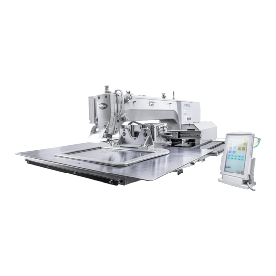
1. Major Parts (1) STOP switch Safety devices: (10) Pulley (3) Power switch (12) Finger gaard (11) Cotton stand (4) Work clamp switch (13) Eye guard (5) Start switch (14) Thread take-ap cover (6) Controi box (15) Motor cover (7) solenold valve (8) Touch screen (9) Thread wiper switch... - Page 9 2. Model TYPICAL ·TC-3020 · Medium Heavy Material Heavy Material Super-heavy Material Lock stitch,pattern tacking sewing machine Sewing machine Line Sing-needle flat seam Highest sewing speed 2,700 rpm Sewing area Max.300×200mm Cloth feeding mode Intermittent feeding(Servo motor drive mode) Stitch Length 0.05-12.7mm...
-
Page 10: Installation Methods
3. Installation Methods CAUTION Installation should be performed by Hold the machine head with both hands well-trained technicians. when tilting it back or returning it to its original position. Please entrust the dealer or a qualified In addition, do not subject the machine electrician to carry out the electric head to extra force while it is tilted wiring. -
Page 11: Installing The Electric Control Box
3.2 Installing the electric control box CAUTION Installation should be performed by two people or more since the control box is heavy. Also, please don't let the control box slip down. It may hurt your feet and cause the control box to malfunction. Before installation, please confirm the model name on the nameplate (a) of the control box (1) and the electric control... - Page 12 il pan ood s rews iler upport le er ase Plain washers pring washers olts Pla e the a hine head onto the ta le · se a rane or hoist to install the sewing a hine · e areful of the following when lowering the a hine head onto the ta le !...
-
Page 13: Tilting Back And Returning The Machine Head
2) After placing the machine head onto the remove the bolt (6) and the spacer (7). table, The bolt (6) and the spacer (7) are necessary for securing the support lever (8) when the machine head is removed from the table, so keep them in a safe place. -
Page 14: Installing The Eye Guard
3.6.Installing the eye guard CAUTION Attach all safety devices before using the sewing machine. If the machine is used without these devices attached, injury may result. (1) Eye guard assembly (2) Screws [2 pcs.] 3.7 Installing the cotton stand (1) Thread stand [NOTE] Fit the washer (2), and then securely tighten the nut (3) so that the cotton... -
Page 15: Lubrication
3.8 Lubrication CAUTION Do not connect the power cord until lubrication is complete. If the foot switch is depressed by mistake, the sewing machine might start operating and injury could result. Be sure to wear protective goggles and gloves when handling the lubricating oil and grease, so that they do not get into your eyes or onto your skin. -
Page 16: Preparation Before Sewing
4.Preparation before Sewing 4.1.Installing the needle CAUTION Turn off the power switch before installing the needle. If the foot switch is depressed by mistake, the sewing machine might start operating and injury could result. 1) Loosen the screw (1). 2) Insert the needle (2) in a straight line as far as it will go, making sure that the long groove on the needle is at the front, and... -
Page 17: Threading The Upper Thread
4.3.Threading the upper thread Thread the upper thread correctly as shown in the illustration below. * When using threading mode for threading, the tension discs (1) will open so that the thread can be threaded more easily. Through surface line Pneumatic clamping device ·... - Page 18 hreading ode is safe e ause the sewing a hine will not start e en when the foot swit h is depressed urn on the power swit h Press the A P e · ower the wor la p · he tension dis s will open hreading the thread ·...
-
Page 19: Winding The Lower Thread
4.4.Winding the lower thread CAUTION Do not touch any of the moving parts or press any objects against the machine while winding the lower thread. Injury or damage to the sewing machine may result. 1) Place the bobbin onto the bobbin winder shaft (1). 2)... -
Page 20: Installing The Bobbin Case
4.5 Installing the bobbin case CAUTION Turn off the power switch before installing the bobbin case. If the foot switch is depressed by mistake, the sewing machine might start operating and injury could result. 50mm 1) Pull the shuttle race cover (1) downward to open it. 2)... -
Page 21: Thread Tension
4.6 Thread tension Thread tension reference Upper thread #20 or equivalent Lower thread #20 or equivalent 1.4~1.8 Upper thread tension (N) 0.3~0.4 Lower thread tension (N) Pre-tension (N) 0.2~0.4 NEEDLE DPX17#19 4.6.1 Lower thread tension Adjust the thread tension to the weakest possible tension by turning the thread tension nut (1) until the bobbin case will not drop by its own weight while the thread end coming out of the... - Page 22 4.7 o e position dete tion efore starting ho e position dete tion that the needle ar is at the needle up stop position urn the pulle until the ridge at the otto of the thread ta e up is aligned with the ar on the ar align ent...
-
Page 23: Use Of Touch Screen
se of tou h s reen etting progra eatures tit h length an e set in the range tit h ount he a i u stit h ount per data is he sewing a hine an hold patterns and the ard an hold patterns he holda le nu er of patterns reated using a large nu er of... - Page 24 un tional o er iew Press to enter progra enu after power up he following i ons will e displa ed on the progra...
- Page 25 Press to display the programming screen. While being operated by the programmer, a number of icons are displayed on the screen which illustrate its operations and functions. Please refer to the "5. Panel operation (basic operation), 6. Panel operation (advanced) and 7. Usage of CF card "...
- Page 26 5.1.4 Making environment settings 3) Following setting up will be displayed. 1) Select ,and press Switches between ON and OFF of the buzzer sound. Switches between ON and OFF of The key click sound. Switches between ON and OFF 2) Select ,and press of the warning display.
- Page 27 5.1.5 Notes on pattern sheet About pattern sheet · Write a pattern on thin plotting paper or use copies of pattern sheet. · Design pattern sheet in full scale. Adjust the size to magnification (2, 5, or 10) when using the magnified input.
-
Page 28: Programming With Icons
5.2 Programming with icons While being operated by the programmer, a number of icons are displayed on the screen which illustrate its operations and functions. This chapter describes the procedure for programming with icons. l Other than programming with the icons, programming with commands is also possible. Holding down allows the user to switch between the mode for programming with icons and themode for programming with commands. - Page 29 2)Make environment settings Make environment settings of the programmer The following items Creates data so that the pitch becomes equal within the specified can be set: Smoothing pitch range when the smoothing function is used. equal pitch Does not create data outside the sewing area when program is being Area check created or edited.
- Page 30 3)Programming screen to display the programming screen. On the launcher screen, select and press If the screen is not displayed, hold down Description display program number Display distance to Displays a distance Display data size from home Image display Display Data input Display setting Display finished...
- Page 31 4)Description of icons Programming Specifying the sewing start point Outline Creating a line Creating a curve Creating a zigzag stitch Creating double stitch data in the reverse direction of the sewing path Creating double stitch data in the same direction as the sewing path Creating a multiple stitch Creating one stitch Creating feed data...
- Page 32 Editing the current program Moving a pattern in parallel by feeding A part of parallel moving continuous programming Repeated copying a pattern Copying a pattern symmetrically to the Y-axis Copying a pattern symmetrically to the X-axis Copying a pattern symmetrically to a point Copying in the reverse direction Deleting a part of the program Editing program...
- Page 33 5.2.2 Procedure for programming with icons The procedure for programming with icons is as follows. 1)Displaying the programming screen On the launcher screen, select and press If the programming screen does not appear, hold down The work clamp moves to the home position and the programming screen is displayed. 2)Starting program creation Select ,and press...
- Page 34 5)Inputting an end code When programming is completed, input an end code to control the machine operation. a. Select ,and press b. Select an end code type with ,and press The following six end codes from 111 to 116 are available, each of which carries out machine operations as shown in the table below.
- Page 35 c. Input the program number, and then press. d. Use to input the comments. e. Press to save the file. Note: To confirm the contents of the save destination, select .The files are saved in flash memory of sewing machine on default。 7)Ending programming Press return to initial screen.
- Page 36 5.2.3 Programming example 1)Programming for each stitch The following describes how to perform programming for each stitch according to the pattern sheet. c. Select ,and then Press , Press Move the work clamp with when the needle point is at point B of Carry out steps 1 to 3 of "Procedure forprogramming with icons".
- Page 37 3)Pattern with curves The following describes how to program a pattern with curves. twice to make a split at corner points C or E. If a split is not made, Be sure to press the corner will be rounded. When a split is made When a split is not made Making more intermediate points such as points B, D, F, G, and H creates smoother curves.
- Page 38 5.2.4 Procedure for modifying program The procedure for modifying the program by using icons is as follows. 1)Calling program to be modified On the launcher screen, select and press . If the programming screen does not appear,hold down Select the pattern no.which need to be modified . Press The work clamp moves to the home position and the programming screen is displayed.
- Page 39 5.2.5 Example of modified program 1)Modifying a part of pattern part of the programmed pattern is changed. The following describes how to modify 5, 6 and 7 to 5', 6' and 7' a、Carry out step 1 of "Procedure for modifying program"...
- Page 40 2)Moving the pattern in parallel (when the first stitch is the sewing start point) The following describes how to move the pattern in parallel when the first stitch is the sewing start point.. a、Carry out step 1 of "Procedure for modifying program".
- Page 41 5.2.6 Checking the program setting and setting attributes It is possible to check the program setting and setting attributes. The following items are displayed Stitch feed trimming basting Option output Low speed Splitting Presser foot height Thread tention trigger Regarding data type items marked with *, you can set their attributes. , and then press Select...
- Page 42 1)Checking each stitch to move backward. to move forward, and press Press The needle steps by each stitch and the data settings are displayed. 2)Checking a series of stitches automatically a、 Input the stitch count to move. to move the needle forward, and press to move it backward.
- Page 43 5.2.7 Deleting program being created/edited Delete program being edited. to display the a、Press The confirmation screen appears. programming screen. c、 to delete program, and then press Press , and then press b、Select to cancel this command.
-
Page 44: Programming With Commands
5.3 Programming with commands Pressing combinations of specific keys on this machine allows programming. These key combinations are called'commands'.This chapter describes the method of programming with commands. Other than programming with commands, programming with icons is also possible.Holding down allows users toswitch between the mode for programming with icons and the mode for programming with commands. - Page 45 Press this key to create a line or a circle. Press this key to set the needle position or use this key as a part of a command. and press to display the programming On the launcher screen, select the icon screen.
- Page 46 2)Description of Commands Moving needle point Proceeding by stitch Returning by stitch Proceeding to the end point Returning to the first point stitch Proceeding by skipping Returning by skipping stitch Skipping to the end point (not applicable at the home position) Skipping to the first point Returning the position to the home position Programming...
- Page 47 Editing program Moving a pattern symmetrical to the Y-axis Moving a pattern symmetrical to the X-axis Moving a pattern symmetrical to a point Resizing a pattern (Input the magnification in the X direction in ,and input the magnification in the Y direction in Copying a resized pattern (Input the magnification in the X direction in ,and input the magnification in the Y direction in Repeated copying...
- Page 48 ther operations嘀 save data(Input the pattern no. in ) eturning to the launher sreen䠀䠀儀 Switching the display size of an image. Hold this key down to switch to the command mode Caneling ommand儀䜀 3)The procedure for programming with commands is as follows. a、Displaying the programming screen icon.
- Page 49 Carrying out no thread trimming Fixing the sewing speed at 1500 rpm or lower Input an End code is selected in the example c、Saving the created program Specify the program number on the operation panel and press the read/write switch for writing into a media.For details of operations, refer to Chapter 6 "Saving program".
-
Page 50: Formatting Media
Formatting media Format media to make them available for the programmer. The following two formatting procedures are provided. This operation is not available in command mode.。 1)Formatting procedure 1 a、 Execute steps 1 to 3 of "Procedures for d、 To start formatting,press reading/saving/deleting program and To cancel formatting, press formatting media". -
Page 51: Checking Program
5.5 Checking program 5.5.1 Displaying program information a、Turn on the machine. b、Select Press Selecting a program display method 5.5.2 Display of thumbnails 1)Display of thumbnails Displays selected program in the folder of a media Displays program number Displays a detail of program. - Page 52 2)Switching between pages To display the next page, press . To display the previous page, press 3)Switching between media .Other information will be displayed according to the different media. a、Select b、 Select the icon of switching destination media .Press 5.5.3 Copying/moving/deleting program/renaming a file Copy, move and delete program, and rename a file.
- Page 53 b、 To start overwriting, press to change the program number To rename the file, press 2)Moving program Select a、 Specify a move destination. When a "A file with the same name exists. Do you overwrite it?" message is issued b、 To start overwriting, press .
-
Page 54: Sewing
6. ewing CAUTION urn off the power swit h at the following ti es f the foot swit h is depressed ista e the sewing a hine ight start operating and ause injur · hen threading the needle · hen repla ing the o in and needle ·... -
Page 55: Using The Stop Switch
6.2 Using the STOP switch If you press the STOP switch (1) while sewing or test feeding is in progress, the CAUTION indicator (2) will illuminate and the sewing machine will stop immediately. <Clearing> 1) Press the RESET key (3). The thread will be trimmed, and then the CAUTION indicator (2) will switch off and the buzzer will stop sounding. -
Page 56: Maintenance
7. Maintenance CAUTION Turn off the power switch before carrying out cleaning. If the foot switch is depressed by mistake, the sewing machine might start operating and cause injury. Be sure to wear protective goggles and gloves when handling the lubricating oil and grease, so that they do not get into your eyes or onto your skin. -
Page 57: Checking The Regulator
7.3 Checking the regulator If water has been collected in the bottle of the regulator (1), turn the drain cock (2) in the direction indicated by an arrow to drain the water. After draining the water, tighten the drain cock (2). 7.4 Cleaning the control box air inlet ports Use a vacuum cleaner to clean the filter in the air inlet ports (2) of the control box... -
Page 58: Standard Adjustments
8. Standard Adjustments CAUTION Hold the machine head with both hands Maintenance and inspection of the sewing when tilting it back or returning it to machine should only be carried out by a its original position. qualified technician. In addition, do not subject the machine Entrust your dealer or a qualified head to extra force while it is tilted electrician to carry out any maintenance... -
Page 59: Adjust Arm Thread Guide
8.2 Adjust arm thread guide The standard position of arm thread guide (1) is when the screw (2) is aligned with the index mark. Loosen the screw (2) and move arm thread guide (1) to adjust. When sewing heavy material, move arm thread ·... -
Page 60: Adjusting The Driver Needle Guard
8.5 Adjusting the driver needle guard Turn the machine pulley to align the tip of the rotary hook with the center of the needle, and then loosen the set screw (2) and turn the eccentric shaft (3) to adjust so that the driver needle guard (1) is touching the needle. -
Page 61: Adjusting The Rotary Hook Lubrication Amount
8.8 Adjusting the rotary hook lubrication amount <Adjusting by changing the pressure on the oil tube> The optimum position is when the head of the set screw (1) is aligned with the edge of the bed. The rotary hook lubrication amount can be adjusted within three turns to the right from that position. -
Page 62: Adjusting The Position Of The Movable Knife
8.9 Adjusting the position of the movable knife 1)Open the top cover and tilt back the machine head. 2)Turn the pulley (1) by hand to lower the needle bar to its lowest position, and push the thread trimmer solenoid (2) as far as it will go. 3)With the collar (3) inserted into the groove of the thread trimmer cam (4), turn the pulley (1) by hand to set the driving lever (5) to the reverse position (when the thread take-up (6) is close to its lowest position). - Page 63 8)Turn the pulley (1) by hand to move the needle bar to its lowest position. 9)Loosen the nut (11), tighten the set screw (12) until the collar (3) is touching the inside of the groove in the thread trimmer cam (4), and then turn it back in the counterclockwise direction by approximately 1/4 of a turn.
-
Page 64: Replacing The Movable And Fixed Knives
8.10 Replacing the movable and fixed knives 1) Loosen the two bolts (1) and then remove the feed plate (2). 2) Open the shuttle race cover,remove the two screws (3) and the two flat screws (4) ,and then remove the nssdle plate (5). -
Page 65: Installing The Feed Plate
8.11 Installing the feed plate [NOTE] Install the feed so that surface with the index mark is facing upward. Place the rear edge,of the feed plate (1) against the stepped part of base plate Y (2) (hatched shaded section (A)).and use a 2 mm diameter pin (such as a needle) to align the hole in the feed plate (1) with the hole in base plate Y (2);then tighten the two bolts (3). -
Page 66: Adjusting The Thread Wiper
8.12 Adjusting the thread wiper 1)Loosen the two screws (3) and shift the entire solenoid setting plate (4) up or down to adjust so that the thread wiper (2) is 15mm in front of the needle center when the plunger (1) of the thread wiper solenoid is driven to the full stroke. -
Page 67: Table Of Error Codes
9 Table of error codes... -
Page 71: Troubleshooting
10 Troubleshooting... - Page 74 This machine may only be operated by adequately trained operators only after having completely read and understood the instruction manual. Parts are subject to changes in design without prior notice. VETRON TYPICAL EUROPE GmbH Clara-Immerwahr-Str. 6 67661 Kaiserslautern, Germany Tel.: +49 6301 320 75-0 Fax: +49 6301 320 75-11 info@vetrontypical.com...
Need help?
Do you have a question about the TC3020GB and is the answer not in the manual?
Questions and answers