
Related Manuals for typical GC24660


Summary of Contents for typical GC24660
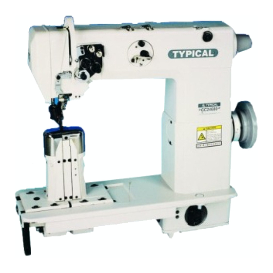
- Page 1 GC24660 Post-bed Single Needle Upper and Lower Roller Feed Sewing Machine GC24680 Post-bed Twin Needle Upper and Lower Roller Feed Sewing Machine OPERATION INSTRUCTION / PARTS MANUAL...
- Page 2 Please don't adjust and repair the machine by non-professionals,except adjusting stitch. Specifications subject to change without notice TYPICAL SEWING MACHINE WANPING MACHINERY CO.,LTD. ADD: WANPING TOWN, WUJIANG CITY, JIANGSU PROVINCE, CHINA TEL: +86-512-63391627 63391278 FAX: +86-512-63391371 63391627 POST. CODE: 215223 Http://www.typicalwpchina.com...
-
Page 3: Table Of Contents
CONTENT CONTENT Operation Instruction Operation Instruction 1. Brief introduction.......................1 1. Brief introduction.......................1 2. Main technical specification..................1 2. Main technical specification..................1 3. Preparation.........................1 3. Preparation.........................1 4. Installing the machine....................1 4. Installing the machine....................1 5. Installing the motor.....................2 5. Installing the motor.....................2 6. -
Page 4: Brief Introduction
2. Main technical specification 2. Main technical specification 1. Brief introduction 1. Brief introduction This series sewing machine is the top product among This series sewing machine is the top product among the post bed sewing machines. It adopts the synchro- the post bed sewing machines. -
Page 5: Installing The Motor
5. Installing the motor (Fig.2) 5. Installing the motor (Fig.2) Align the balance wheel belt groove A with motor Align the balance wheel belt groove A with motor pulley belt groove B by moving the motor C pulley belt groove B by moving the motor C leftward and rightward. -
Page 6: Installing The Knee Lifter Device
8. Installing the knee lifter device (Fig.5) 8. Installing the knee lifter device (Fig.5) Put the knee lifter device into the connector A, then Put the knee lifter device into the connector A, then tighten the screw C. The position of knee lifter bell tighten the screw C. -
Page 7: Winding The Bobbin Thread
11. Winding the bobbin thread (Fig.8) 11. Winding the bobbin thread (Fig.8) Install the bobbin B to the bobbin winder spindle, Install the bobbin B to the bobbin winder spindle, pass the thread A between the tension disc E, and pass the thread A between the tension disc E, and then wind the thread a few turns around the bobbin. -
Page 8: First Sewing
14. First sewing (Fig.11) 14. First sewing (Fig.11) 1. Lift the presser foot lift lever. 1. Lift the presser foot lift lever. 2. Close the roller foot. 2. Close the roller foot. 3. Lay down the materials. 3. Lay down the materials. 4. -
Page 9: Adjusting The Bobbin Thread And The Needle Thread
17. Adjusting the bobbin thread and the needle thread (Fig.14) 17. Adjusting the bobbin thread and the needle thread (Fig.14) Normal stitch form should be as shown in Fig.14. Normal stitch form should be as shown in Fig.14. When abnormal stitches occur with puckering or When abnormal stitches occur with puckering or thread breakage, the tension of needle thread and thread breakage, the tension of needle thread and... -
Page 10: Adjusting The Pressure Of The Roller Foot
19. Adjusting the pressure of the roller foot (Fig.16) 19. Adjusting the pressure of the roller foot (Fig.16) Clockwise Clockwise Counter Clockwise Counter Clockwise Please adjust the roller foot according to the material Please adjust the roller foot according to the material to be sewn. -
Page 11: Adjusting The Position Of The Rotating Hook And Needle
21. Adjusting the position of the rotating hook and needle (Fig.18) 21. Adjusting the position of the rotating hook and needle (Fig.18) When the tip of the needle is raised by 1.8mm from its When the tip of the needle is raised by 1.8mm from its lowest position, the position of the rotating hook and lowest position, the position of the rotating hook and the needle should be set as shown in Fig.18. -
Page 12: Adjusting The Clearance Between The Hook Point And The Needle
24. Adjusting the clearance between the hook point and the needle (Fig.21) 24. Adjusting the clearance between the hook point and the needle (Fig.21) The clearance between the hook point and needle is The clearance between the hook point and needle is about 0.05mm, which has been adjusted before del about 0.05mm, which has been adjusted before del ivery. -
Page 13: Arm And Bed
1. Arm and bed 1. Arm and bed... - Page 14 1. Arm and bed 1. Arm and bed No . No . Name Name Part number Part number Remark Remark Single needle Single needle Double needle Double needle Face plate Face plate Screw (long) Screw (long) Screw (short) Screw (short) Rear cover Rear cover Screw...
-
Page 15: Thread Tension Parts
2. Thread tension parts 2. Thread tension parts... - Page 16 2. Thread tension parts 2. Thread tension parts No . No . Name Name Part number Part number Remark Remark Single needle Single needle Double needle Double needle Thread guide stud Thread guide stud Middle thread guide Middle thread guide Washer Washer Screw...
-
Page 17: Upper Shaft Thread Take-Up Parts
3. Upper shaft thread take-up parts 3. Upper shaft thread take-up parts... - Page 18 3. Upper shaft thread take-up parts 3. Upper shaft thread take-up parts No . No . Name Name Part number Part number Remark Remark Single needle Single needle Double needle Double needle Thread take-up lever Thread take-up lever Washer Washer Retainer Retainer Bearing...
-
Page 19: Needle Bar Parts
4. Needle bar parts 4. Needle bar parts... - Page 20 4. Needle bar parts 4. Needle bar parts No . No . Name Name Part number Part number Remark Remark Single needle Single needle Double needle Double needle Upper feed shaft Upper feed shaft Spacer Spacer Retainer Retainer Rear bearing Rear bearing Bushing Bushing...
-
Page 21: Feed Mechanism
5. Feed mechanism 5. Feed mechanism... - Page 22 5. Feed mechanism 5. Feed mechanism No . No . Name Name Part number Part number Remark Remark Single needle Single needle Double needle Double needle Retainer Retainer Spacer Spacer Retainer Retainer Bearing Bearing Bushing Bushing Crank Crank Screw Screw Clamp Clamp Screw...
-
Page 23: Presser Bar Lifter Parts
6. Presser bar lifter parts 6. Presser bar lifter parts... - Page 24 6. Presser bar lifter parts 6. Presser bar lifter parts No . No . Name Name Part number Part number Remark Remark Single needle Single needle Double needle Double needle Rubber plug Rubber plug Presser bar bushing Presser bar bushing Screw Screw Presser bar...
-
Page 25: Upper Roller Feed Parts
7. Upper roller feed parts 7. Upper roller feed parts... - Page 26 7. Upper roller feed parts 7. Upper roller feed parts No . No . Name Name Part number Part number Remark Remark Single needle Single needle Double needle Double needle Driven link assembly Driven link assembly Screw Screw Felt Felt Clamp Clamp Screw...
-
Page 27: Lower Shaft
8. Lower shaft 8. Lower shaft... - Page 28 8. Lower shaft 8. Lower shaft No . No . Name Name Part number Part number Remark Remark Single needle Single needle Double needle Double needle Bevel gear Bevel gear Screw Screw Collar Collar Screw Screw Bevel gear Bevel gear Synchronic wheel Synchronic wheel Bearing...
-
Page 29: Post Bed
9. Post bed 9. Post bed... - Page 30 9. Post bed 9. Post bed No . No . Name Name Part number Part number Remark Remark Single needle Single needle Double needle Double needle Screw Screw Spacer Spacer Thread distributor Thread distributor Felt Felt Screw Screw Screw Screw Collar Collar Bearing...
-
Page 31: Post Bed (Parts Only For Double Needle Machine)
10. Post bed (parts only for double needle machine) 10. Post bed (parts only for double needle machine) - Page 32 10. Post bed (parts only for double needle machine) 10. Post bed (parts only for double needle machine) No . No . Name Name Part number Part number Remark Remark Single needle Single needle Double needle Double needle Adjusting cam Adjusting cam Left hook post-bed Left hook post-bed...
-
Page 33: Thread Winder
11. Thread winder 11. Thread winder... - Page 34 11. Thread winder 11. Thread winder No . No . Name Name Part number Part number Remark Remark Single needle Single needle Double needle Double needle Thread pass plate Thread pass plate Screw Screw Screw Screw Spring Spring Thread tension disc Thread tension disc Thread tension shaft Thread tension shaft...
-
Page 35: Accessories
12. Accessory 12. Accessory... - Page 36 12. Accessory 12. Accessory No . Name Part number Remark Single needle Single needle Double needle Double needle Oil pot Oil pot Spool stand assembly Spool stand assembly Spool stand assembly Spool stand assembly Bed leg Bed leg Pin shaft Pin shaft Pin shaft Pin shaft...
Need help?
Do you have a question about the GC24660 and is the answer not in the manual?
Questions and answers