Table of Contents
Advertisement
Advertisement
Table of Contents

Related Manuals for typical TW1-571


Summary of Contents for typical TW1-571
- Page 1 TW1 571 / 574 / 591 INSTRUCTION MANUAL...
- Page 3 Instruction Manual This manual applies to all machines of the mentioned type from the following serial # 1000011 number onward: 4153-3-570590-2-2...
- Page 4 This Instruction Manual is valid for all models and subclasses listed in the chapter "Specifications ".
-
Page 5: Table Of Contents
7.08. Swing out roller presser 7.09. Edge trimmer -725/04 for 571 7.010. Edge trimmer -725/04 for 574 and 591 7.011. Control panel (only with Typical-Eco drive or Typical-Pico drive) Installation and commissioning 8.01. Installation 8.01.01. Adjusting the table-top height 8.01.02. - Page 6 11.05. Circuit diagrams 11.05.01. Reference list for the Circuit diagrams 11.05.02. Block diagram TYPICAL 570 / 590 with control unit P40 ED 11.05.03. Circuit diagrams 91-191 524-95 11.05.04. Block diagram TYPICAL 570 / 590 with control unit P44 PD-L 11.05.05.
-
Page 7: Safety
Safety Safety Directives This machine is constructed in accordance with the European regulations contained in the conformity and manufacturer’s declarations. In addition to this Instruction Manual, also observe all generally accepted, statutory and other regulations and legal requirements and all valid environmental protection regulations! The regionally valid regulations of the social insurance society for occupational accidents or other supervisory organizations are to be strictly adhered to! General notes on safety... -
Page 8: Safety Symbols
● It is the obligation of the user to ensure that none of the safety mechanisms are removed or deactivated. ● It is the obligation of the user to ensure that only authorized persons operate and work on the machine. Further information can be obtained from your TYPICAL agent. -
Page 9: Operating And Specialist Personnel
Safety Operating and specialist personnel Operating personnel .05.01 Operating personnel are persons responsible for the equipping, operating and cleaning of the machine as well as for taking care of problems arising in the sewing area. The operating personnel is required to observe the following points and must: ●... -
Page 10: Danger Warnings
Safety Danger w arnings A working area of 1 m must be kept free both in front of and behind the machi- ne, so that easy access is possible at all times. Never put your hands or fingers in the sewing area during sewing! Danger of injury by the needle! While setting or adjusting the machine do not leave any objects on the table nor in the needle plate area! Objects may be trapped or flung out of the machine! -
Page 11: Proper Use
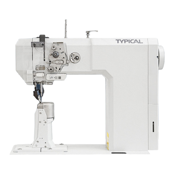
Proper use Proper use The TYPICAL 571 is a single needle, high-speed post bed sewing machine (post to the left of the needle) with driven feed wheel and roller presser and synchronized needle. The TYPICAL 574 is a two-needle, high-speed post bed sewing machine with driven feed... -
Page 12: Specifications
Emission sound level at the workplace at appropriate speed (Noise measurement in accordance with DIN 45 635-48-A-1, ISO 11204, ISO 3744, ISO 4871) TYPICAL 571 and 591, model A + B at a speed of 2400 spm.: ......L = 79 dB(A) ■... -
Page 13: Needles And Threads
Needle t hicknesss (Nm) ness in 1/100 syst em syst em syst em Model max. synt het ic f or Typical 571 f or Typical 574 f or Typical 591 ▲ 60/3 40/3 134 - 35 15/3 134 - 35 ▲... -
Page 14: Disposal Of Machine
Disposal of Machine Disposal of Machine ● Proper disposal of the machine is the responsibility of the customer. ● The materials used for the machine are steel, aluminum, brass and various plastic materials. The electrical equipment comprises plastic materials and copper. ●... -
Page 15: Transportation, Packing And Storage
Transportation, packing and storage Transportation, packing and storage Transportation to customer‘ s premises The machines are delivered completely packed. Transportation inside the customer‘s premises The manufacturer cannot be made liable for transportation inside the customer‘s premises nor to other operating locations. It must be ensured that the machines are only transported in an upright position. -
Page 16: Explanation Of Symbols
Explanation of symbols Explanation of symbols In this instruction manual, work to be carried out or important information is accentuated by symbols. These symbols have the following meanings: Note, information Cleaning, care Lubrication Maintenance, repairs, adjustment, service work (only to be carried out by technical staff) -
Page 17: Controls
On/off sw itch 77-005 Fig. 7 - 01 Fig. 7 - 01a Machines w ith Typical-EcoDrive Machines w ith Typical-PicoDrive ● The power supply to the machine is swit- ● Operate main switch 2 to switch the ched on or off by turning switch 1. -
Page 18: Bobbin Thread Monitoring With Stitch Counting (Only With Ecodrive)
Controls Bobbin thread monitoring w ith stitch counting (only on machines with EcoDrive) ● After the pre-set number of stitches have been sewn, diode 1 flashes. ● After the thread has been trimmed and the bobbin changed, the stitch counting begins anew. -
Page 19: Lever For Lifting Roller Presser
Controls Lever for lifting roller presser ● The roller presser can be raised by tur- ning lever 1. 61-006 Fig. 7 - 05 Knee lever ● The roller presser can be raised by pres- sing the knee lever 1 in the direction of the arrow. -
Page 20: Key For Setting Stitch Length
Controls Key for setting stitch length ● The stitch length is set by pressing key 1 and turning the balance wheel (see Chap- ter 9.07 Setting the stitch length). 61-007 Fig. 7 - 07 Sw ing out roller presser ● When the roller presser is raised, it can be swung out by pulling it lightly down- wards. -
Page 21: Edge Trimmer -725/04 For 571
Controls Edge trimmer -725/04 for 571 Keep your hands away from the moving knife! Danger of injury! Sw itch on knife drive: ● Move lever 1 backwards. The knife moves into operating position. Sw itch off knife drive: ● Press lever 1. The knife swings back- wards. -
Page 22: Edge Trimmer -725/04 For 574 And 591
Controls Edge trimmer -725/04 for 574 and 591 61-083 61-008 Fig. 7 - 10 Keep your hands away from the moving knife! Danger of injury! Sw itch on knife drive: ● Move lever 1 backwards. The knife moves into operating position. Sw itch off knife drive: ●... -
Page 23: Control Panel (Only With Typical-Eco Drive Or Typical-Pico Drive)
Controls Control panel (only on machines with Typical-Eco drive or Typical-Pico drive) The description can be found in the separate instruction manual for the control panel. -
Page 24: Installation And Commissioning
Installation and commissioning Installation and commissioning The machine must only be mounted and commissioned by qualified personnel! All relevant safety regulations are to be observed! If the machine is delivered without a table, it must be ensured that the frame and the table top which you intend to use can hold the weight of the machine and the motor. -
Page 25: Fitting The Tilt Lock
Installation and commissioning Fitting the tilt lock .01.02 Switch off the machine! Danger of injury if the machine is the machine is started acci- dentally! ● Screw on the tilt lock 1, provided in the accessories, using screw 2. Do not operate the machine wi- thout tilt lock 1. -
Page 26: Mounting The Flange Motor
Installation and commissioning Mounting the flange motor Mounting the flange motor to the bearing plate .02.01 Fig. 8 - 04 ● Attach bearing plate 1 to motor 2 with screws 3 as shown in Fig. 8 - 04. ● Remove the wedge from motor shaft 4. ●... -
Page 27: Mounting The Toothed Belt And Adjusting The Tension
Installation and commissioning Mounting the toothed belt and adjusting the tension .02.03 Fig. 8 - 06 ● In this position fit toothed belt 1. ● Swing the bearing plate 2 of the motor, so that the toothed belt is tensioned. ●... -
Page 28: Connecting The Plug-In Connections And Earth Cables
Installation and commissioning Connecting the plug-in connections and earth cables P40 ED P44 PD-L Fig. 8 - 08... -
Page 29: Connecting The Safety Switch
● Connect all plugs as labelled to the control box . ● On the TYPICAL 574 with the control unit P40 ED plug 1 of the adapter cable (see blow-up) should be inserted in socket X2. The motor and the "external" plug of the synchronizer should be connected to the "motor"... -
Page 30: Fitting The Reel Stand
Installation and commissioning Fitting the reel stand ● Fit the reel stand as shown in Fig. 8-10. ● Afterwards insert the stand in the hole in the table top and secure it with the nuts provided. Fig. 8 -10 Commissioning ●... -
Page 31: Basic Position Of The Machine Drive Unit
Installation and commissioning Basic position of the machine drive unit On machines with Typical-EcoDrive and control unit P40 ED .09.01 ● Switch on the machine. ● Press the TE/speed key tw ice to select the input mode. ● Select parameter "798" by pressing the corresponding + /- key, and select service level C, see Chapter Selecting the user level in the instruction manual for the control panel. -
Page 32: On Machines With Typical-Picodrive And Control Unit P44 Pd-L
Installation and commissioning On machines with Typical-PicoDrive and control unit P44 PD-L .09.02 ● Switch on the machine. ● Call up the parameter input by pressing the "scroll" key. ● To switch the function keys to input (LED in the TE key lights up), press the TE key. -
Page 33: Setting Up
Danger of injury due to unintentional starting of the machine! Only use needles from the system intended for the machine, see Chapter 3 Specifications. TYPICAL 571 und 591 TYPICAL 574 ● Raise the roller presser 1 and swing it ● Raise the roller presser 1 and swing it out.. -
Page 34: Winding The Bobbin Thread, Adjusting The Thread Tension
Setting up Winding the bobbin thread, adjusting the thread tension Fig. 9 - 02 ● Place an empty bobbin 1 onto bobbin shaft 2. ● Thread the bobbin in accordance with Fig. 9-02 and wind it anti-clockwise around bobbin 1 a few times. ●... -
Page 35: Removing/Inserting The Bobbin Case
Setting up Removing/Inserting the bobbin case Switch the machine off! Danger of injury if the machine is started accidentally! Removing the bobbin case: ● Open the post cap. ● Raise latch 1 and remove bobbin case 2. Inserting the bobbin case: ●... -
Page 36: Threading The Needle Thread And Regulating Its Tension (571 /591)
Setting up Threading the needle thread and regulating its tension on model 571 and 591 129-037 Fig. 9 - 05 Switch the machine off! Danger of injury if the machine is started accidentally! ● Tilt up the eye guard 1. ●... -
Page 37: Threading The Needle Thread And Regulating Its Tension ( 574)
Setting up Threading the needle thread and regulating its tension on model 574 129-038 Fig. 9 - 06 Switch the machine off! Danger of injury if the machine is started accidentally! ● Tilt up the eye guard 1. ● Thread both needle threads as shown in Fig. 9-06. ●... -
Page 38: Setting The Stitch Length
2 opposite the bottom edge 3 of the belt guard recess. Adjusting the stitch counter for the bobbin thread control (only on machines (only on machines with Typical Motor and P40 (ED) control unit) Please see the description in the separate control panel instruction manual. werden. -
Page 39: Care And Maintenance
Care and maintenance Care and maintenance Servicing and maintenance intervals Clean ............daily, more frequently if in continuous operation Oil level (thread lubrication/hook lubrication)..........daily, before use Oil the hook....................daily, before use Lubricate the bevel gears ................... once a year Check/adjust air pressure ................daily, before use Clean air filter of air-filter/lubricator ..............when required These maintenance intervals are calculated for the average running time of a single shift operation. -
Page 40: Oiling The Hook
● If required refill oil through hole. Use only oil with a mean viscosity of 22.0 mm /s at 40°C and a density of 0.865 g/cm 15° C. We recommend TYPICAL sewing machine oil Best.-Nr. 280-1-120 144. Fig. 10 - 03... -
Page 41: Lubricating The Bevel Gears
Use both hands to set the sewing head upright! Danger of crushing between the sewing head and the table top! We recommend TYPICAL sodium grease with a dripping point of approx. 150° C, Order No. 280-1-120 243. -
Page 42: Filling The Oil Reservoir Of The Thread Lubrication Unit
Fig. 10 - 05 Parameter settings (only on machines with Typical-EcoDrive and control unit P40ED or Typical-PicoDrive and control unit P44 PD-L ) ● The selection of the user level and the alteration of parameters is described in the sepa- rate instruction manual for the drive unit. - Page 43 0 = 1:1 (571 and 591) 1 = variable (574) ◆ On the TYPICAL 574 the machine class 6 and on the TYPICAL 571 and 591 the machine class 4 must be entered. Further parameters and the description for an internet update of the machine software and reset /cold start of the machine can be found in the instruction manual for the control panel.
-
Page 44: Mounting The Table Top
Mounting the table top Mounting the table top Tilted w ork base 2x dowel pins Ø 12 x 37 Table top cutout... -
Page 45: Mounting The Table Top (With Typical-Ecodrive / P 40 Ed)
Mounting the table top Mounting the table top (with Typical-EcoDrive and control unit P 40 ED) Stand position 906-3550-005/895 Controlbox P 40 ED Speedcontrol unit Controlunit for - 725/..; -726/.. View:Underside table top 91-263 432-95 Vers. 02.12.03... -
Page 46: Mounting The Table Top (With Typical-Picodrive / P44 Pd-L)
Mounting the table top Mounting the table top (with Typical-PicoDrive and control unit P44 PD-L) Stand position 906-3550-005/895 Controlbox P 44 PD-L Speedcontrol unit View:Underside table top... -
Page 47: Circuit Diagrams
Reference list for the Circuit diagrams 91-191 524-95 and 91-191 534-95 .05.01 Control package P40 ED P44 PD-L 91-191 524-95 91-191 534-95 Control unit Typical P40ED Control unit Typical P44PD BDF-S2 control panel PicoTop control panel Sewing head recognition(OTE) Start capacitor Sewing lamp... - Page 48 Circuit diagrams Control package P40 ED P44 PD-L 91-191 524-95 91-191 534-95 Thread tension release plug (FSL) Control panel plug Start inhibitor plug Sewing head recognition plug Automatic presser foot lift (-910/..) Thread trimmer ( -900/.. ) Y2.1 Backtacking device (-911/..) - roller presser Y2.2 Backtacking device(-911/..) - feed...
-
Page 49: Block Diagram Typical 570 / 590 With Control Unit P40 Ed
Block diagram Version 04.02.08 Block diagram TYPICAL 570 / 590 with control unit P40 ED .05.02 570/590 Synchronizer PD3 only on the 574 BDF - S2 Drive / Ministop long incremental transducer Speedcontrolunit software download Control unit P40 ED Control package P40 ED... -
Page 50: Circuit Diagrams 91-191 524-95
Circuit diagrams 91-191 524-95 Version 18.06.07 Part 1 Circuit diagrams 91-191 524-95 .05.03... - Page 51 91-191 524-95 Circuit diagrams Version 18.06.07 Part 2...
-
Page 52: Block Diagram Typical 570 / 590 With Control Unit P44 Pd-L
Block diagram Version 04.02.08 Block diagram TYPICAL 570 / 590 with control unit P44 PD-L .05.04 570/590 Synchronizer PD6 only on the 574 BDF - PICO TOP Drive / Ministop long incremental transducer Speedcontrolunit software download power switch Control unit P44 PD-L... - Page 53 91-191 534-95 Circuit diagrams Version 12.03.08 Part 1 Circuit diagrams 91-191 534-95 .05.05...
-
Page 54: Circuit Diagrams 91-191 534-95
Circuit diagrams 91-191 534-95 Version 12.03.08 Part 2... -
Page 55: Wearing Parts
Roller presser 35 mm Ø, 4,0 mm wide coated with plastic-material 91-263 433-91 Roller presser 30 mm Ø, 4,0 mm wide, toothed TYPICAL 571, 574 TYPICAL 591 TYPICAL 571, 574, 591 91-176 329-05 TYPICAL 574 91-176 321-05 11-108 093-15 91-173 664-15... - Page 56 Wearing parts for subclass -900/83 11-130 173-15 95-774 855-05 95-774 856-05 11-108 852-15 95-774 853-05 95-774 880-05 99-137 151-45 91-171 049-05 91-171 042-05 95-774 464-25 91-700 996-15 571-725/.. 574-725/..; 591-725/.. 11-173 168-15 11-130 167-15 91-119 202-04/001 91-011 165-04/00110 For more knives see parts list...
- Page 57 Notes...
- Page 58 Certi cate for Energy international ISO9001 ISO14001 international CE Ecolabelling Product Conservation Product XI’AN TYPICAL INDUSTRIES CO., LTD. VETRON TYPICAL EUROPE GmbH No. 335, South Taibai Road Clara-Immerwahr-Str. 6 Xi’an 710068, P.R.China 67661 Kaiserslautern, Germany Tel.: +86-29-88279093 / / 88279150 / / 88279151 Tel.: +49 6301 320 75-0...
Need help?
Do you have a question about the TW1-571 and is the answer not in the manual?
Questions and answers