
Subscribe to Our Youtube Channel
Related Manuals for typical TW1-2B


Summary of Contents for typical TW1-2B
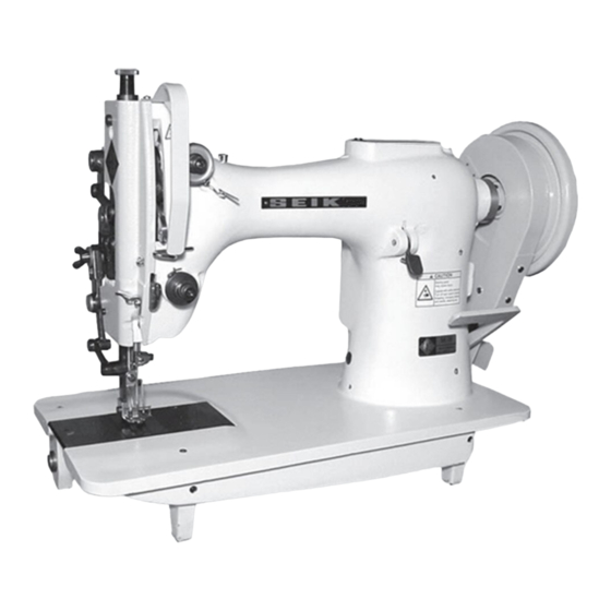
- Page 1 TW1-2B/TW1-2BL20 Single Needle Top and Bottom Feed Extra Heavy-duty Lockstitch Sewing Machine OPERATION INSTRUCTION / PARTS MANUAL...
- Page 2 Please don't adjust and repair the machine by non-professionals,except adjusting stitch. Specifications subject to change without notice TYPICAL SEWING MACHINE WANPING MACHINERY CO.,LTD. ADD: WANPING TOWN, WUJIANG CITY, JIANGSU PROVINCE, CHINA TEL: +86-512- 63391278 FAX: +86-512-63391371 POST. CODE: 215223 Http://www.typicalwpchina.com...
-
Page 3: Table Of Contents
CONTENTS Operation instruction Operation instruction 1. Brief introduction 1. Brief introduction 2. Main technical specification 2. Main technical specification 3. Operation and preparation 3. Operation and preparation 4. Installing the clutch motor 4. Installing the clutch motor 5. Connecting the clutch motor lever to the pedal 5. -
Page 4: Operation Instruction
Operation Instruction... -
Page 5: Brief Introduction
1. Brief introduction 2. Main technical specification Model TW1-2B/2BL20 extra heavy duty top and Model TW1-2B/2BL20 extra heavy duty top and Model TW1-2BL20 TW1-2B Parameter bottom feed lockstitch sewing machine with large bottom feed lockstitch sewing machine with large Max. Sewing speed Max. -
Page 6: Connecting The Clutch Motor Lever To The Pedal
5. Connecting the clutch motor lever to the pedal (Fig. 2) A. The optimum tilt angle of pedal with floor is A. The optimum tilt angle of pedal with floor is 10 12mm approx. 20 30 degree. approx. 20 30 degree. B. -
Page 7: Installing The Bobbin Winder
8. Installing the bobbin winder (Fig. 5) Align pulley (B) of the bobbin winder with the Align pulley (B) of the bobbin winder with the outside of the belt (C). And there should be a proper outside of the belt (C). And there should be a proper clearance between them so that the pulley can be clearance between them so that the pulley can be contacted with the belt when stop latch thumb lever... -
Page 8: Trail Run
10. Trail run When the machine left out of operation for a quite When the machine left out of operation for a quite long time and used again or a new complete machine, long time and used again or a new complete machine, remove the rubber plug and face plate on the top of remove the rubber plug and face plate on the top of the machine head, oil it thoroughly. -
Page 9: Threading The Needle Thread
13. Threading the needle thread (Fig. 9) When threading the needle thread, the needle bar When threading the needle thread, the needle bar must be its highest position. The correct threading must be its highest position. The correct threading steps as below: steps as below: (a) Long thread retainer (a) Long thread retainer... -
Page 10: Oiling The Thread Take-Up Part
16. Oiling the thread take-up parts (Fig. 12) Thread take-up parts adopt woolen thread oiling. Thread take-up parts adopt woolen thread oiling. After a long time using, its function lost. So it must After a long time using, its function lost. So it must be replaced with a new one. -
Page 11: Adjusting The Thread Take-Up Spring
19. Adjusting the thread take-up spring (Fig. 15) The normal sewing range of thread take-up spring The normal sewing range of thread take-up spring is 5 is 5 8mm. For sewing light duty materials (small 8mm. For sewing light duty materials (small stitch length), weaken the spring tension and widen stitch length), weaken the spring tension and widen the sewing range of spring. -
Page 12: Timing Between He Needle And The Rotating Hook
21. Timing between the needle and the rotating hook (Fig. 18,19) (1) Adjusting the position of needle bar. (1) Adjusting the position of needle bar. Turn the balance wheel to make the needle bar (B) Turn the balance wheel to make the needle bar (B) to its lowest position. -
Page 13: Installing And Uninstalling The Hook
22. Installing and uninstalling the hook (Fig. 20) Lift the needle bar to its highest position; remove Lift the needle bar to its highest position; remove the needle plate, needle and bobbin case. Loosen the the needle plate, needle and bobbin case. Loosen the bobbin case holder bracket screw (C), and take out bobbin case holder bracket screw (C), and take out position bracket (A). -
Page 14: Feed Timing Adjustment
25. Feed timing adjustment (Fig. 24,25,26) (1) Standard position Turn the balance wheel to lower feed dog (A) Turn the balance wheel to lower feed dog (A) until it is horizontal with the surface (B) of needle until it is horizontal with the surface (B) of needle plate. -
Page 15: Upper Feed Adjustment
26. Upper feed adjustment (Fig. 27) During the sewing, the center gauge (L) between During the sewing, the center gauge (L) between the walking foot sliding block and its shaft can be the walking foot sliding block and its shaft can be adjusted according to the differences of the friction adjusted according to the differences of the friction coefficients of the friction coefficients of materials... -
Page 16: Parts Manual
Parts Manual... -
Page 18: Arm And Bed
1. Arm and bed Part number Parts name Remark 6K4-001 TW1-2B 8KT4-001 TW1-2B 6K4-002 TW1-2B TW1-2BL20 KT4-002 6K4-003 Face plate 6K4-004 Big screw for face plate 6K2-015 Small screw for face plate 6K4-005 Upper thread finger of face plate 6K1-004... -
Page 19: Thread Take-Up Mechanism
2. Thread take-up mechanism 17 18 36 37 69 70 -14-... - Page 20 Needle bar crank 6K1-026 Set screw 6K1-027 Position screw 6K1-028 Upper shaft TW1-2B 8KT1-001 Upper shaft TW1-2B L20 6K1-029 Front bushing for upper shaft 6K1-030 Screw for front bushing 6K1-031 Rear bushing for upper shaft 6K1-032 Oil pipe 6K1-033 Oil felt...
-
Page 21: Bottom Feed Mechanism
3. Bottom feed mechanism 11 12 62 63 75 76 73 74 -16-... - Page 22 Feed link 6K2-045 Feed cam 6K1-048 Screw for feed cam 6K2-046 Pin shaft 6K2-015 Set screw 6K2-047 Feed shaft TW1-2B 8KT2-001 Feed shaft TW1-2B 6K2-048 Rear bushing for feed shaft Front bushing for feed h ft 6K2-049 6K2-050 Screw 6K2-051...
-
Page 23: Presser Bar Mechanism
4. Presser bar mechanism -18-... - Page 24 4. Presser bar mechanism Part number Parts name Remark 6K3-001 Pulling bar 6K3-002 Connector for pulling bar 6K2-007 Screw 6K3-003 6K3-004 Lever TW1-2B 8KT3-001 Lever TW1-2B 6K3-005 6K1-065 Screw 6K3-006 Spring for lever 6K3-007 Position pin 6K3-008 Screw for lever...
-
Page 25: Upper Feed Mechanism
5. Upper feed mechanism -20-... - Page 26 Sliding block 6K5-023 Washer 6K5-024 Papilionaceous nut 6K5-025 Front crank for vibrating shaft Taper pin GB117-86 A4 27 6K5-026 Vibrating shaft TW1-2B 8KT5-001 Vibrating shaft TW1-2BL20 6K5-027 Front bushing for vibrating shaft 6K5-028 Screw 6K5-029 Feed bracket 6K1-059 Set screw...
-
Page 27: Accessories
6. Accessories -22-... - Page 28 24# 2 7# 6K6-009 Bobbin winder assembly 33TF-014 Screwdriver (Small) 33TF-013 Screwdriver (Medium) 33TF-012 Screwdriver (Big) Cross screwdriver 35WF6-002 Spanner Spanner Spanner S=2.5 Spanner 6K6-002 Oil pan TW1-2B 8KT6-002 Oil pan TW1-2BL20 V-belt Length 1270mm 22T9-007F1 Hinge 22T9-007F2 Hinge cover -23-...
Need help?
Do you have a question about the TW1-2B and is the answer not in the manual?
Questions and answers